It does more harm than good, but you must keep the capacitor.
It wont be a problem to try, at least ill find out if the problem is in the gain stage. Maybe capacitor of 220mF for decopleing the catode biasing ressistor at gain stage make the problems.
I would omit that capacitor too.
I agree, maybe ill try red-led biassing to omit the ressistor also.
BTW im using AC heating, maybe regulated one with LM 317T will help also. Honestly i dont know if heating has influence of square signal responce.
I would omit that capacitor too.
You were right. Removing the decoupling catode capacitor improved the responce on 100Hz square, but its still far from ideal.
After removing the catode follower stage responce was awfull.
Adding red led diodes doesnt change anything, the responce is same like without decoupling catode capacitor.
In general sound is improved without decoupling capacitor and red leds instead of catode resistors. More tight bass.
I myself would not bother with the square wave response. A clean filament current is beneficial in other respects. Again, I would use non-bypassed cathode resistor and no cathode follower.
I myself would not bother with the square wave response. A clean filament current is beneficial in other respects. Again, I would use non-bypassed cathode resistor and no cathode follower.
Its what i did, without decoupling capacitor it sounds muvh better. Lso red-led biassing helps.
I need an advice.
How to skip the second stage(catode follower) and use the signal from first tube (gain stage) i know i should add and capacitor from anode to output, but there should be some ressistor from anode to ground also?
I think there has been some investigation into noise in diodes zeners and LEDs....somewhere in the forum...I believe that the conclusion was that red LED's were the least noisy...and provided a stable and predictable voltage step...
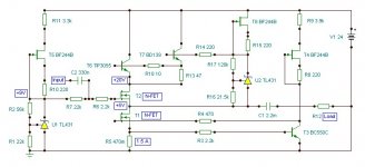
Thanks for the circuit.
I deleted my drawings because it looks like 5 year child art peace.
I really like to try other topology with fet's for example your circuit. But i like to finished what i started with first. My intention is to achieve the best performance by process of meassuring and then to carefully listen the difference.
With red-led instead of catode ressistor this tube preamp sounds like transistor one. It seems that it works "faster". But its an subjective observation. For sure bass is more tight, but reason for that could be the removing of decoupling catode capacitor. This evening i'll try to measure and to listen only gain stage.
Im very interested, what is your curent system setup?
I think there has been some investigation into noise in diodes zeners and LEDs....somewhere in the forum...I believe that the conclusion was that red LED's were the least noisy...and provided a stable and predictable voltage step...
I readed the same about red-leds, in many articles they are described like better devices for biasing then ressistors.
I don't know....There seem to be so so many opinions and options that it hard to keep track...I can easily understand why people select diode bias, as it in my sims clearly reduces distortion....but the same does current sources....so to say what LED bias does for the sound is difficult to say....Its also funny to see...that in sims capacitance around nodes in cascodes improves distortion figures, but sometimes they don't improve sound at all....I think that we to some extent "think" static steady state while music is dynamic and transient...maybe that is a reason why listening not always correlates with measurements
it is better to avoid TL431 or other noisy voltage references. Or filter that noise out, lot of examples in Walt Jung papers, how to do this. Or use LED's, they are much quiter.
Christer Noise Test Paper 1.4
Noise measurement by Terry Ritter
Noise of LEDs and some more
Christer Noise Test Paper 1.4
Noise measurement by Terry Ritter
Noise of LEDs and some more
Last edited:
Agree with MiiB, simulations do not reflect some imperfections of parts, especially of electrolytics. For voltage reference, from my empirical observations, the resistor+electrolytic is worst of all (make sound dark), most of kinds of Zeners are really noisy, red light diodes are very good (applicable if voltage not so high), transistor substitute for Zener (two bjt transistors + three resistors) also very good (applicable also for high voltages), the lithium battegy voltage reference + polypropylene cap - very good (if applicable, current consumption from the battery must be very small)
when using red leds for biasing...i normally shunt it to gnd with silvered mica..or other good small caps.. don't really know if it can reduce the 0.something u-volts noise.
when using red leds for biasing...i normally shunt it to gnd with silvered mica..or other good small caps.. don't really know if it can reduce the 0.something u-volts noise.
In that case what happens with AC signal?
when using red leds for biasing...i normally shunt it to gnd with silvered mica..or other good small caps.. don't really know if it can reduce the 0.something u-volts noise.
LEDs and Zeners have extremely fast pulse responce, so, since we must not need to filter our noise from LEDs, small fast shunt cap is generally not needed to them, except for the case of long chain of LEDs used with relatively high parasitic inductance.
- Status
- Not open for further replies.
- Home
- Amplifiers
- Solid State
- Modified Follower-99 With HF Transistors