You can see the inside in post 463, when the back and the top were still missing.
Nikon: I agree you should vent some hot air from inside your F5. Caps don't like heat, right?
Last edited:
10 year old Son Of Zen - Sounded too good to make pretty!
Hi Zen folk🙂
I thought it was about time I posted my SOZ - built in about 2002. I started this as a test project... intending to take it all apart and build one of the beautiful creations you can see earlier this thread. But... I met my wife just as I completed the last solder joints and have not found the time since then to make it pretty! Another reason I have for failing to re-build this amp is that I simply could not do without it for even one day! Maybe when I retire (or employ others to do all my work for me) I will dismantle this beast and rebuild it in leather, oak, velum and brass but... until that day comes I will just enjoy the sound it makes!
To explain the poor pictures:
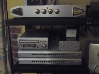
The power supply for the SOZ is housed in an old IBM 286 PC case with a wooden plank on the front. This contains a huge standard transformer I found which has high current secondaries at 55-0-55 and 110-0-110 (and various additional taps I'm not using) - This beast was built for a large rack-mount fire detection system. I forewent the inductors in the recommended power supply and just used large number of Phillips 1000uf military grade caps. Separate secondaries supply the left and right channels. The 0-240V mains is supplied through the obligatory variac.
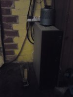
The SOZ amps are shown at the bottom of the 2nd picture. I used (slightly scratched so rejected) cases from CCTV equipment. Each has a rear/top/centrally mounted 110V AC fan, for cooling, powered direcly from the tramsformer 110v AC secondaries. The resistors are mounted on a lateral metal plate within the from half of each unit while the mosfets are fixed to heatsinks on either side towards the back of the cases. The colling is actually quiet up to at least half power. I never run the amps above 20V (30% on the variac) as there is no need to. I have central heating and I worry that I haven't adjusted the DC bias in a long while🙂
I use an Alchemist Forseti Pre-amp. This was the first and only pre-amp with a balanced-line output I could find here in the UK. Don't tell me it's a poor amp without listening to my system first!!!!
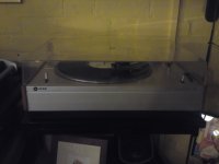
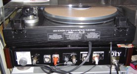
The last photo shows my pride and joy: a Leak 2001 Transcription Unit turntable with Shure V15 mk3 cartridge.
The speakers are another story and so not pictured... but you can guess they look a little Heath Robinson🙂
I've lived with this for 10 years and really don't care what it looks like... I can always close my eyes and enjoy the music🙂
I will replace these awful pictures with better ones when we have a sunny day🙂
Hi Zen folk🙂
I thought it was about time I posted my SOZ - built in about 2002. I started this as a test project... intending to take it all apart and build one of the beautiful creations you can see earlier this thread. But... I met my wife just as I completed the last solder joints and have not found the time since then to make it pretty! Another reason I have for failing to re-build this amp is that I simply could not do without it for even one day! Maybe when I retire (or employ others to do all my work for me) I will dismantle this beast and rebuild it in leather, oak, velum and brass but... until that day comes I will just enjoy the sound it makes!
To explain the poor pictures:
The power supply for the SOZ is housed in an old IBM 286 PC case with a wooden plank on the front. This contains a huge standard transformer I found which has high current secondaries at 55-0-55 and 110-0-110 (and various additional taps I'm not using) - This beast was built for a large rack-mount fire detection system. I forewent the inductors in the recommended power supply and just used large number of Phillips 1000uf military grade caps. Separate secondaries supply the left and right channels. The 0-240V mains is supplied through the obligatory variac.
The SOZ amps are shown at the bottom of the 2nd picture. I used (slightly scratched so rejected) cases from CCTV equipment. Each has a rear/top/centrally mounted 110V AC fan, for cooling, powered direcly from the tramsformer 110v AC secondaries. The resistors are mounted on a lateral metal plate within the from half of each unit while the mosfets are fixed to heatsinks on either side towards the back of the cases. The colling is actually quiet up to at least half power. I never run the amps above 20V (30% on the variac) as there is no need to. I have central heating and I worry that I haven't adjusted the DC bias in a long while🙂
I use an Alchemist Forseti Pre-amp. This was the first and only pre-amp with a balanced-line output I could find here in the UK. Don't tell me it's a poor amp without listening to my system first!!!!
The last photo shows my pride and joy: a Leak 2001 Transcription Unit turntable with Shure V15 mk3 cartridge.
The speakers are another story and so not pictured... but you can guess they look a little Heath Robinson🙂
I've lived with this for 10 years and really don't care what it looks like... I can always close my eyes and enjoy the music🙂
I will replace these awful pictures with better ones when we have a sunny day🙂
Attachments
Pearl II
Hi, here is my Pearl II, sitting with my LP12.
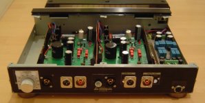
On the backside, from the left, the load impedance adjustment (10 ohm ... 1kOhm), followed by the input and output of the left channel, the ground terminal, and the input and outputs of the right channel. To the right, the connector for the external power supply (thats a "brick" with a 60VA toroid, followed by two separated paths with bridge rectifier / caps / cap multiplier), feeding the phono stage with pretty good DC. (Less than 1mV of noise, under load). Glad I put that connector so low, that left some space for the PassDIY sticker ;-)
The symmetrical connectors are not used at this point, since this was supposed to be the "test bed" for phono stages but for now I just enjoy the music...
Inside, the two PCBs sit in individual “chambers”, all star-grounded at the back panel. On the right side is the input filter for the power supply coming in. When cranking up the volume, there is only a little bit of hiss but no hum so I guess thats a good sign.
The case is salvaged from a Sony satellite radio, the wooden side panels going along nicely with the turntable case. All I had to do was to make holes for the connectors, and create a new frontpanel (just a rectangular piece of aluminum, with two LEDs).
what should I say.... after a couple oscillation issues that were solved with the help of wayne and nAr, it works beautifully!
Hi, here is my Pearl II, sitting with my LP12.
On the backside, from the left, the load impedance adjustment (10 ohm ... 1kOhm), followed by the input and output of the left channel, the ground terminal, and the input and outputs of the right channel. To the right, the connector for the external power supply (thats a "brick" with a 60VA toroid, followed by two separated paths with bridge rectifier / caps / cap multiplier), feeding the phono stage with pretty good DC. (Less than 1mV of noise, under load). Glad I put that connector so low, that left some space for the PassDIY sticker ;-)
The symmetrical connectors are not used at this point, since this was supposed to be the "test bed" for phono stages but for now I just enjoy the music...
Inside, the two PCBs sit in individual “chambers”, all star-grounded at the back panel. On the right side is the input filter for the power supply coming in. When cranking up the volume, there is only a little bit of hiss but no hum so I guess thats a good sign.
The case is salvaged from a Sony satellite radio, the wooden side panels going along nicely with the turntable case. All I had to do was to make holes for the connectors, and create a new frontpanel (just a rectangular piece of aluminum, with two LEDs).
what should I say.... after a couple oscillation issues that were solved with the help of wayne and nAr, it works beautifully!
Attachments
Hi, here is my Pearl II, sitting with my LP12.
On the backside, from the left, the load impedance adjustment (10 ohm ... 1kOhm), followed by the input and output of the left channel, the ground terminal, and the input and outputs of the right channel. To the right, the connector for the external power supply (thats a "brick" with a 60VA toroid, followed by two separated paths with bridge rectifier / caps / cap multiplier), feeding the phono stage with pretty good DC. (Less than 1mV of noise, under load). Glad I put that connector so low, that left some space for the PassDIY sticker ;-)
The symmetrical connectors are not used at this point, since this was supposed to be the "test bed" for phono stages but for now I just enjoy the music...
Inside, the two PCBs sit in individual “chambers”, all star-grounded at the back panel. On the right side is the input filter for the power supply coming in. When cranking up the volume, there is only a little bit of hiss but no hum so I guess thats a good sign.
The case is salvaged from a Sony satellite radio, the wooden side panels going along nicely with the turntable case. All I had to do was to make holes for the connectors, and create a new frontpanel (just a rectangular piece of aluminum, with two LEDs).
what should I say.... after a couple oscillation issues that were solved with the help of wayne and nAr, it works beautifully!
Nice to see your pics and the fact it works fine now 🙂 Enjoy 😎
Mini-A@work (Sorry for bad quality):
Waiting for the MUR860´s for the rectifier boards.
An externally hosted image should be here but it was not working when we last tested it.
Waiting for the MUR860´s for the rectifier boards.
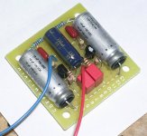
lastes build - jboz
well its not really and amp but still mighty powerful.
I love the jboz , 3rd one this year.
getting the layout down - took about 45 minutes to build, all p2p and it worked, which is always nice.
not sure where it will go, the other I made loves working with my 6em7 amp. really tightens up the low end. thanks again Mr. Pass for a simple and wounder design.😀😀
here is a pic - enjoy,
Jeff
Attachments
well its not really and amp but still mighty powerful.
I love the jboz , 3rd one this year.
getting the layout down - took about 45 minutes to build, all p2p and it worked, which is always nice.
not sure where it will go, the other I made loves working with my 6em7 amp. really tightens up the low end. thanks again Mr. Pass for a simple and wounder design.😀😀
here is a pic - enjoy,
Jeff
Cute as can be!
well its not really and amp but still mighty powerful.
I love the jboz , 3rd one this year.
getting the layout down - took about 45 minutes to build, all p2p and it worked, which is always nice.
not sure where it will go, the other I made loves working with my 6em7 amp. really tightens up the low end. thanks again Mr. Pass for a simple and wounder design.😀😀
here is a pic - enjoy,
Jeff
It definitely encourages others to give it a try.
Nice work.
yo Woodie !
nice to see ya here and there
😉
Hi, my friend, from half way around the planet 🙂
well its not really and amp but still mighty powerful.
I love the jboz , 3rd one this year.
getting the layout down - took about 45 minutes to build, all p2p and it worked, which is always nice.
not sure where it will go, the other I made loves working with my 6em7 amp. really tightens up the low end. thanks again Mr. Pass for a simple and wounder design.😀😀
here is a pic - enjoy,
Jeff
Curious, what's this ?
D.
getting the layout down - took about 45 minutes to build, all p2p and it worked, which is always nice.
Could you indulge us with a photo of the other side of your board?? 🙂
JBOZ PDF
I dont think there is anything under there except wires. Maybe thats what you were looking for, but here is the schematic. Well, its one of the schematics that Pass posted but there were others from I think both Lineup and EUVL and probably several more. People were commenting that this pdf was gain of 50 and that a source resistor of 100R might be better for a line stage but do your own research on that as I picked that info up at about 1AM this morning and am not sure I am right.
Uriah
Attachments
I dont think there is anything under there except wires.
Yes, exactily! That's what I would like to see! 🙂 😀 😎🙄🙁😛😱
Aha! And now we know who you truly are! One of those dirty birds always trying to get an upskirt shot of the other guys amp! LOL
transformer cases
I see few opt for the transformer case. Is this considered an unnecessary expense? I find it odd the case is nearly as expensive as the transformer but the principal of using one seems legit, all things considered.
I see few opt for the transformer case. Is this considered an unnecessary expense? I find it odd the case is nearly as expensive as the transformer but the principal of using one seems legit, all things considered.
go to store ;
look for a can with adequate dia & tasty content
buy it
go home and enjoy in content
clean da can , cut it to adequate length , bend sharp (just cut ) edge/end to make nice seam ;
spray it ( first prepare for paint as usual)
voila !
( take care with clamping can to case ; if you think using central toroid bolt for that , you must isolate can from bolt)
Well I suppose I was actually looking forward to something of a more technical response, but apparently a reply from the "Court Jester" will suffice under the circumstances.
I'm thinking the 'real' cover is a good idea considering the size of the can of beans required to act as surrogate transformer cover. (That's a lot of beans - think of the gas!) Perhaps a canned ham would do better? I understand sand is often used to fill the void.
I'm thinking the 'real' cover is a good idea considering the size of the can of beans required to act as surrogate transformer cover. (That's a lot of beans - think of the gas!) Perhaps a canned ham would do better? I understand sand is often used to fill the void.
- Home
- Amplifiers
- Pass Labs
- Pictures of your diy Pass amplifier