Hi All, this is my first post although I am a long standing lurker.
Are there any F5 boards available or anyone planning on doing an F9 layout.
Are there any F5 boards available or anyone planning on doing an F9 layout.
After a couple of email exchanges with Peter Daniels, he says he doesn't have them in stock; though no further info on when the new boards (if any) will be ready. Let's sit tight and wait patiently 😀
Cheers~
Cheers~
After a couple of email exchanges with Peter Daniels, he says he doesn't have them in stock; though no further info on when the new boards (if any) will be ready. Let's sit tight and wait patiently 😀
Cheers~
Cviller just posted he has a few up for sale, I've only built with Peter's, but many I know have also used Cviller's boards. Similarly, Tech-DIY is supposed to be offering kits soon....Peter did tell me he still had plenty of power supply boards.
russellc
I am building a pair of F5 monoblocks. Each one with a transformer, a full diode bridge for each rail, and four 22.000uF caps with the 4x 0.1r 3w each full dual rail board.
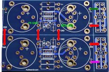
Only one quick question: Is it ok if I put jumpers as in the way shown on the attached picture? These pads will be unused, so I am guessing that placing 3 of them could be better for making a dual supply PSU. I don't think it will make a ground loop.
Power will be taken to an F5 board from the marked outputs. These are your F5 boards. There is a wire from the F5 ground pad to the marked pad on the picture. The return of the speaker will go where marked in the picture.
Can anyone give it a quick look and check if it is alright?
FYI, it will carry all caddock MK132, and Mills for the power resistors. Capacitors are Mundorf MLytic SI, Schottky TO-247 rectifiers 🙄
I don't think I will place the thermistor and the current limiter circuitry on the F5. I want that bunch of small Hi-Q resistors and pairs of caps sounding at their bests. Adding more stuff get close to double the amount of components in the circuit.
Thanks, regards
Regi
Attachments
Hi,
you have shown 4pads on each PCB with red links.
Are any or all of these 4pads connected with traces on the underside?
you have shown 4pads on each PCB with red links.
Are any or all of these 4pads connected with traces on the underside?
Yes, Andrew, they are connected on the underside.
Teabag, I understand that you are joining both rail's grounds between the two gnd pads under and above the marked v+/v- output pads? Then, in which pads are you soldering the ground from the F5 board and the return from the speaker?
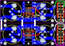
I'll do the same drawing in the underside, it should be clearer for you guys.
Sorry for a minor mistake. I wrongly drawed the connections from the diode bridges on the previous post. Not important for the matter.
Teabag, I understand that you are joining both rail's grounds between the two gnd pads under and above the marked v+/v- output pads? Then, in which pads are you soldering the ground from the F5 board and the return from the speaker?
I'll do the same drawing in the underside, it should be clearer for you guys.
Sorry for a minor mistake. I wrongly drawed the connections from the diode bridges on the previous post. Not important for the matter.
Attachments
Regi,
Don't tie the two in the middle, just one on left between v+ and v-. Attach speaker ground to it, board grounds to it, and signal ground to board or here. Then attach CL60 to it, and other side to Chassis and IEC ground. Shouldn't hum.
Don't tie the two in the middle, just one on left between v+ and v-. Attach speaker ground to it, board grounds to it, and signal ground to board or here. Then attach CL60 to it, and other side to Chassis and IEC ground. Shouldn't hum.
When you actually say "it", what are you referring to?Regi,
Don't tie the two in the middle, just one on left between v+ and v-. Attach speaker ground to it, board grounds to it, and signal ground to board or here. Then attach CL60 to it, and other side to Chassis and IEC ground. Shouldn't hum.
Can I use some pads for the task of connecting spk return, signal ground, earthing...?
Last edited:
And is there an elegant way of performing it? I am afraid the only solution to be a bunch of flying cables soldered to a copper jumper. That couldn't be an option with such a nice board 😕sorry, the ground connection between v+ and v- all in that place.
Can you post a picture of yours?
I will look for a pic, but that's the way I do it. Not sure where I picked it up.
I think someone from Poland had drawn it out for me that way.
I think someone from Poland had drawn it out for me that way.
Peter shows lots of pictures in the Universal Power Supply thread in the Vendor Forums (under Audio Sector) that should explain everything. Postings #4 and #32 in particular may be of interest to Regiregi22's query.
Peter shows lots of pictures in the Universal Power Supply thread in the Vendor Forums (under Audio Sector) that should explain everything. Postings #4 and #32 in particular may be of interest to Regiregi22's query.

I haven't yet found an elegant way to hook up grounds. Its a pity doing that way having so many holes on the PSU board.
On another matter, I've seen that the recommended transformers are around 250VA or 300VA ratings. I know these are recommended values for long term stability, lower heat, constant current class A consumption, bla bla bla...
But in practice, if my maths are right, one F5 channel would consume 1.3A times 36v (2x18vac voltage swing), which is around 47VA.
Now my question is not wether is it recommended a 47VA trafo (I know it isn't), but if one F5 channel just consumes 47VA.
Does one F5 channel needs just 47VA?
47VA, no.
Because the transformer does not see/feel/react to/heat up the same as it would do passing 1.3Aac through a resistor.
Because the transformer does not see/feel/react to/heat up the same as it would do passing 1.3Aac through a resistor.
thanks
It has something to be with the inductance, or because of the lower resistance than a transformer coil use to have comparing it with a resistor?
Regards,
Regi
It has something to be with the inductance, or because of the lower resistance than a transformer coil use to have comparing it with a resistor?
Regards,
Regi
Is it OK one slow-blow 1.25A fuse to protect one F5? I am going dual psu for it, but Nelson Pass psu schematic doesn't specify if it is for one channel or two. I live in 230v. I will use the thermistors in the transformer.
it's mainly due to the heating effect in the primary and the secondary depending on I^2 rather than simply I.It has something to be with the inductance, or because of the lower resistance than a transformer coil use to have comparing it with a resistor?
The current pulses that charge up a capacitor input filter demand that the transformer be de-rated according to the manufacturer's data.
- Status
- Not open for further replies.
- Home
- Group Buys
- F5 pcb group buy...