I am looking for some F5 version 2 boards. I can see the V1 boards in the DIY audio store but no v2.
I am currently assembling an F5 (one channel already working - yeah!!!) and never heard about first or 2nd F5 version. Maybe you are talking about one of the multiple itinerations that the design took.
AFAIK, there was a balanced operation version and that multiple output devices version.
I am currently using Peter Daniel's boards, which are more compact because pad sizes are designed for Caddock MK132 resistors. If you are going to use standard axial 1/4W resistors, they won't fit without bending. I am building the circuit with the Caddocks, no thermistor for temp-co and no current limiting circuitry.
Will post some pictures later 😀
Regards,
Regi
I am building the circuit with the Caddocks, no thermistor for temp-co and no current limiting circuitry.
Will post some pictures later 😀
Regards,
Regi
Yeah! Yeah!
This will be a nice setup.😀😀😀
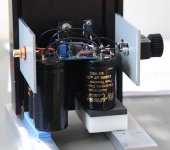
Here are some pictures.
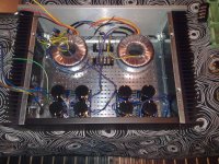
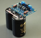
It is dual mono construction, one PSU per channel, each one loaded with 4x 22.000uF of MLytic AG capacitors in CRC configuration. The amp adds a total of 176.000uF and 2x 250VA toroids.
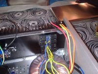
Diodes are IR Hexfred ultrafast and ultrasoft recovery. They are mounted on the heatsink too for a total of 8 per channel.
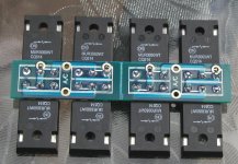
Resistors are Caddock MK132 and Mills. Output devices are IRFP9240 and IRFP240 from International Rectifier. I think that almost everybody has used them from other manufacturers, like Toshiba or Fairchild, has someone tried IR?
For wiring I am using just strapped AC power cords, because I have lots of them and because they have relatively "high" copper gauge.
It is dual mono construction, one PSU per channel, each one loaded with 4x 22.000uF of MLytic AG capacitors in CRC configuration. The amp adds a total of 176.000uF and 2x 250VA toroids.
Diodes are IR Hexfred ultrafast and ultrasoft recovery. They are mounted on the heatsink too for a total of 8 per channel.
Resistors are Caddock MK132 and Mills. Output devices are IRFP9240 and IRFP240 from International Rectifier. I think that almost everybody has used them from other manufacturers, like Toshiba or Fairchild, has someone tried IR?
For wiring I am using just strapped AC power cords, because I have lots of them and because they have relatively "high" copper gauge.
Attachments

I forgot to say that this is the most silent amplifier I have built. All my previous gainclones were almost dead, but placing the ear next to the tweeter it could be possible to hear a little bit noise. Now it isn't there even touching the tweeter with my ear 😀
Still have to finish it, let it burn in quite some hours and make serious listenings, but after a pair of hours playing one channel all I can say is that it is very detailed, sometimes too much, but I like that new sensation. It's like "ehhh, I don't want to hear THAT! and THAT neither!" he he he.
Still have to finish it, let it burn in quite some hours and make serious listenings, but after a pair of hours playing one channel all I can say is that it is very detailed, sometimes too much, but I like that new sensation. It's like "ehhh, I don't want to hear THAT! and THAT neither!" he he he.
Regarding that, you are quite right, differences in gain are obvious, I am considering a 28dB against 15dB from the F5.
On another matter, I am a bit afraid of DC coupling it. I never know to what am I going to hook it up (DC wise), and even having it in a controlled enviroment, you never know what kind of transients are you gonna get by means of shutting down the DAC or the preamp or whatever. So, what value of input capacitor is an acceptable value? Keep in mind that in this projecto cost is not a concern, but space and funtionality can be.
By having 100k input to ground, I can suppose that 2uF can be enought, but should I place it after or before the 1k input series resistor? Any recommendation regarding the value of the input cap?
I know this is alway a subjective question but I have to ask about it. Is there a cap model known to work well in the F5? This is a futile question, I know it. Just want to heard something from the voice of the experience 😀ç
Thanks, regards,
Regi
Are boards still available ? I'd like to make a dual mono as shown above.
I just placed the order for more F5 amp boards and they will be available next week, PS boards are available as well.
The current price is $18 per stereo set of F5 and $20 for dual voltage power supply pcb, shipping included, paypal payment to my e-mail address posted here: DIY Chip Amplifier Kits, PCB's, Components and Information.
More info on PS boards here: http://www.diyaudio.com/forums/audio-sector/149672-universal-power-supply-pcb.html
Attachments


I just placed the order for more F5 amp boards and they will be available next week, PS boards are available as well.
The current price is $18 per stereo set of F5 and $20 for dual voltage power supply pcb, shipping included, paypal payment to my e-mail address posted here: DIY Chip Amplifier Kits, PCB's, Components and Information.
More info on PS boards here: http://www.diyaudio.com/forums/audio-sector/149672-universal-power-supply-pcb.html
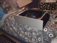
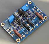
Glad to hear more boards will be available. Looking at your fourth pic across the top, the one that shows th amp in seperate pieces, I notice the wires going to your diode boards are fairly thick. I found the holes in the diode boards to be very small. How did you fit such large wires? Reaming out the holes? I was afraid that might mess up the contact to the pad?
Thanks,
Russellc
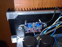
Russel, using TO-247 devices, there are two options, two or three legged devices. I had the ones with 2 legs, so I had to bend one pin once inserted in its hole to reach the next hole and solder it there. That will give you a quite "big" area to solder heavy wires, right onto the leg.
Looking at your fourth pic across the top, the one that shows th amp in seperate pieces, I notice the wires going to your diode boards are fairly thick. I found the holes in the diode boards to be very small. How did you fit such large wires?
According to 300VA Plitron datasheet: http://shop.plitron.com/specs/0770XX201.pdf those are 14ga wires and this is what I used without any need to enlarge rectifier board holes.
Anything bigger is really not needed. However, you can always make the holes larger but make sure wires are soldered to pads on both side of the board.
Attachments
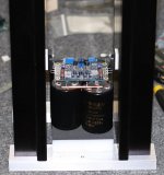
that's neat !
what would an output stage look like when done that way?
Ready to plug in a Mongrel style front end.
what would an output stage look like when done that way?
Ready to plug in a Mongrel style front end.
Quite sexy leaving some clearance between the mosfets for to-220 power resistors 😛what would an output stage look like when done that way?
- Status
- Not open for further replies.
- Home
- Group Buys
- F5 pcb group buy...