Overview Version.
8x IRFP240PbF IRFP9240PbF to ± 100V, output voltage ± 95V/4Ω (1000W)
4x IRFP240PbF IRFP9240PbF at ± 70V, output voltage ± 65V/4Ω (500W)
2x IRFP240PbF IRFP9240PbF at ± 50V, output voltage ± 45V/4Ω (250W)
1x IRFP240PbF IRFP9240PbF at ± 40V, output voltage ± 35V/4Ω (150W)
8x IRFP240PbF IRFP9240PbF to ± 100V, output voltage ± 95V/4Ω (1000W)
4x IRFP240PbF IRFP9240PbF at ± 70V, output voltage ± 65V/4Ω (500W)
2x IRFP240PbF IRFP9240PbF at ± 50V, output voltage ± 45V/4Ω (250W)
1x IRFP240PbF IRFP9240PbF at ± 40V, output voltage ± 35V/4Ω (150W)
It looks stable, but under biased imo. Increase the bias on the output stage & those small glitches just under & over the zero crossing (with square waves) should disappear..
Overview Version.
8x IRFP240PbF IRFP9240PbF to ± 100V, output voltage ± 95V/4Ω (1000W)
Not very realist..
IRFs devices need at least 200mA , if not more, to work
linearly enough...
Using this minimal value yield a 1.6A quiescent current with 8 pairs,
that is, about 320W thermal dissipation at iddle...
You can reduce the idle current, but linearity wil be catastrophic..
Ah, i think that explains things 😉He says he has 20mA per one pair of IRFs.
Not even HItachi s lateral fets can be used with so low
quiescent currents , but if linearity is not a concern ,
20mA should do it, it can even be recuced to 0 , pure Class B,
why not ?. But then, we are no more talking about high fidelity...
quiescent currents , but if linearity is not a concern ,
20mA should do it, it can even be recuced to 0 , pure Class B,
why not ?. But then, we are no more talking about high fidelity...
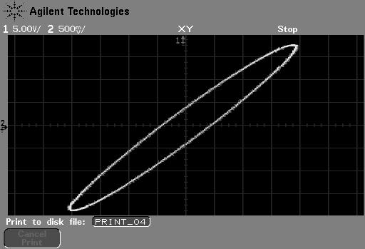
This lissajous picture doesn t say nothing if
it s measured at full power...
Can you post a picture of a 20KHZ sine
with a 5V peak to peak amplitude or the
same lissajous figure with this output level
amplitude?..
it s measured at full power...
Can you post a picture of a 20KHZ sine
with a 5V peak to peak amplitude or the
same lissajous figure with this output level
amplitude?..
Figure is 5 ~ 6% performance. For 1W Lissajous was equally smooth. Necessary bias current can be accurately determined. Set to be very sensitive to 100kHz.
Look at the size of the heatsink used.
The main heatsink is below the PCB. Is much larger, ventilated fan. It is not easy to see.
This lissajous picture doesn t say nothing if
it s measured at full power...
Can you post a picture of a 20KHZ sine
with a 5V peak to peak amplitude or the
same lissajous figure with this output level
amplitude?..
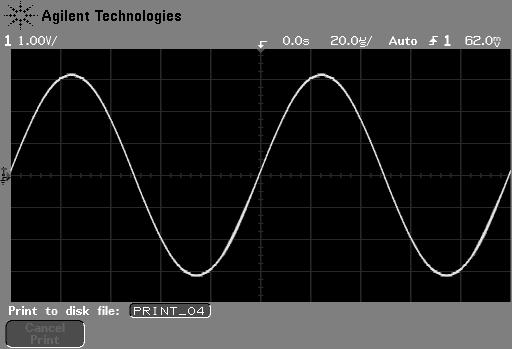
Sine 10kHz, 3V peak
It is no use, unless someone just place small sensor between his ear and brain.
As I experienced that there is a dynamic compressor in my hearing tool (my ear of course).
As I experienced that there is a dynamic compressor in my hearing tool (my ear of course).
Please can you show us
the output at say around 1 and 10 volts pk pk output at 10 khz when loaded capacitively with perhaps a 1 or 2 uF cap.
Thanks
the output at say around 1 and 10 volts pk pk output at 10 khz when loaded capacitively with perhaps a 1 or 2 uF cap.
Thanks


May I suggest these signals?
When it vibrates so pretty, I guess something is wrong.
When it vibrates so pretty, I guess something is wrong.
Federmann, the signals are SMPTE IMD 250Hz+8kHz and CCIF IMD 13+14kHz. The CCIF IMD would test the amplifier zero crossings at different slopes and amplitudes. The SMPTE IMD would show shape of high frequency, low amplitude signal carried on high amplitude, low frequency signal. Again, it reveals crossover distortion, if present.
🙂 I have similar signals on a Denon test CD...
Mr Federmann,
please can we see the amplifier capacitively loaded as I mentioned before in post #594
Not a simulation, a real 'scope measurement on the amplifier.
It's a very valid test IMO.
Mr Federmann,
please can we see the amplifier capacitively loaded as I mentioned before in post #594
Not a simulation, a real 'scope measurement on the amplifier.
It's a very valid test IMO.
Federmann, the signals are SMPTE IMD 250Hz+8kHz and CCIF IMD 13+14kHz. The CCIF IMD would test the amplifier zero crossings at different slopes and amplitudes. The SMPTE IMD would show shape of high frequency, low amplitude signal carried on high amplitude, low frequency signal. Again, it reveals crossover distortion, if present.
The question was
the output at say around 1 and 10 volts pk pk output at 10 khz when loaded capacitively with perhaps a 1 or 2 uF cap. Thanks
I amplifier no longer. Values will supply the next piece.
I amplifier no longer. Values will supply the next piece.
🙂 Don't quite understand the phrase 🙂 "I amplifier no longer"
Scope screen shots would be good if that's what you mean 🙂
- Status
- Not open for further replies.
- Home
- Amplifiers
- Solid State
- Influence of the delay amplifiers for listening characteristics