1: Adjust R2 until Ic(Q1)=Ic(Q2)
2: Adjust R1 until Ic(Q3)=Ic(Q4)
3: repeat until both LTP's are balanced
You're right, if the constant temperature and supply voltage. Temperature dependence of voltage reference LED diode is different from the temperature dependence of BE of the transistor. Transistor parameters are also dependent.
The main contribution to voltage drop at the base resistance Q1 - Q3 and Q4 - Q2.
Ib is dependent on Ic as well.
The tree factors affecting Vdif at DC are:
1: Ib
2: Ic balance
3: Vbe
A DC servo does not necessarily solve either of these problems. It only corrects the symptom - output voltage offset.
I believe there are better ways to ensure optimal Vdif.
- keantoken
Last edited:
Parameters of semiconductors with temperature changes. DC servo, PI controller deals mainly thermal stability. P-I controller knows overload amplifier.
0V output voltage is derived from Vdif.
... which is the same as saying: "the output voltage of an amp comes from the input voltage". Very deep thought 😉
jd
... Very deep thought 😉
jd
🙂 Pleas, be kind. That's one small step for mankind, one giant leap for a Ruprecht.
Parameters of semiconductors with temperature changes. DC servo, PI controller deals mainly thermal stability. P-I controller knows overload amplifier.
Federmann,
It may be a language issue, but the thermal stability is not addressesd by the servo/PI, UNLESS you mean the thermal stability of the DC offset.
What normally is meant by thermal stability is the thermal stability of the output stage, which is not addressed by the servo.
What do you mean by: "P-I controller knows overload amplifier"?
jd
🙂 Pleas, be kind. That's one small step for mankind, one giant leap for a Ruprecht.
???
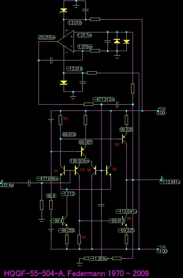
Federman, I've added part numbers to your schematic to illustrate.
Assume that Vbe(Q1)=Vbe(Q2)
Assume that Vbe(Q3)=Vbe(Q4)
Assume that for any transistor Vbe increases with Ic.
Following this, Vdif will be equal if and only if Ic(Q1)=Ic(Q2)=Ic(Q3)=Ic(Q4).
So, say Ic(Q1) is not equal to Ic(Q2), and this causes Vdif to be -2mV.
The servos will add 2mV to the base of Q2, but the base of Q1 will still be 0V.
So you see that the real problem is the Ic of the LTP's.
Ic(Q1) roughly equals Vbe(Q5)/R2.
Ic(Q3) roughly equals Vbe(Q6)/R1.
So really the only way to minimize Vdif is to:
1: Adjust R2 until Ic(Q1)=Ic(Q2)
2: Adjust R1 until Ic(Q3)=Ic(Q4)
3: repeat until both LTP's are balanced
After doing this there should be no need for a servo since, as you say, Vout is derived from Vdif.
- keantoken
For precise adjustment of just R2
No worries. The amplifier is completely stable.
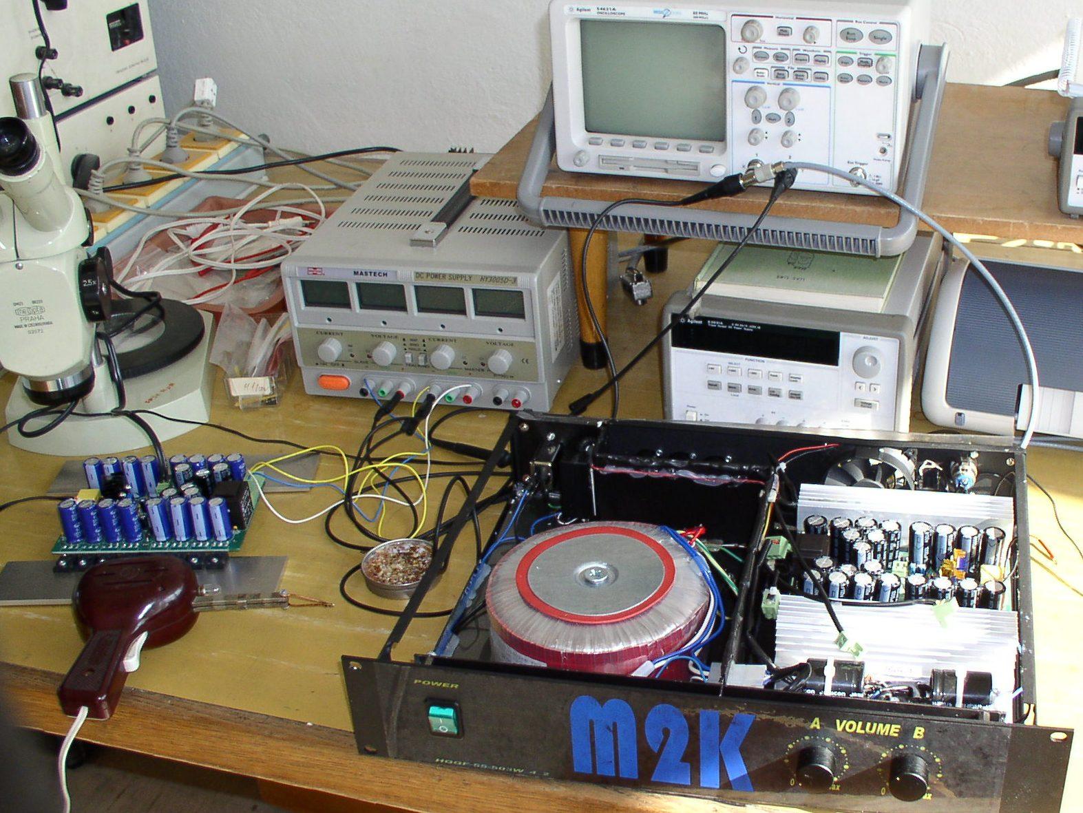
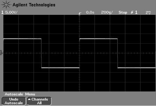
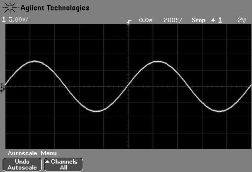
4 pairs IRFP240PbF and IRFP9240PbF
Sinus P = (U * I) / 2 = (75V * 75V / 4Ω) / 2 ≈ 700W
Rectangle P = (U * I) = (75V * 75V / 4Ω) ≈ 1400W
4 pairs IRFP240PbF and IRFP9240PbF
Sinus P = (U * I) / 2 = (75V * 75V / 4Ω) / 2 ≈ 700W
Rectangle P = (U * I) = (75V * 75V / 4Ω) ≈ 1400W
- Status
- Not open for further replies.
- Home
- Amplifiers
- Solid State
- Influence of the delay amplifiers for listening characteristics