My circuit is not about the JLH, but the NTP... I can't just delete the whole frontend... But if the JLH won't do I would like a similar quasicomp output stage, VAS type like the current one.
I just got it working somehow not sure what I did wrong before. Now it's totally silent. I added a 10nF cap to ground at the input. I think it was a grounding problem... I think it was the weird spurious EMI that was doing it. No signs of oscillation.
That's a good idea though, ferrite bead between emitters...
- keantoken
One possibility is you had a bad contact too. It's good you fixed it. Now you can enjoy the sound 🙂
I'm thinking about that bad contact thing.
I loaded the CD I had been listening to through the CD player into the computer and it sounded worse. So I think there may be something up, maybe the constant 100kHz signal is causing problems (shouldn't this be filtered out by the soundcard?)
- keantoken
I loaded the CD I had been listening to through the CD player into the computer and it sounded worse. So I think there may be something up, maybe the constant 100kHz signal is causing problems (shouldn't this be filtered out by the soundcard?)
- keantoken
Don't forget you got Germaniums. An NTP of those has about one silicon drop.
I don't know if that opens any possibilities??? or just another can of worms...
I hand matched that set somewhere in the mid 70's (HFEs, not year 1970).
I don't know if that opens any possibilities??? or just another can of worms...
I hand matched that set somewhere in the mid 70's (HFEs, not year 1970).
Last edited:
I'm thinking just a can of worms. I don't think silicon would properly temperature compensate germanium.
I think it's interesting to see the similarities between the NTP as I have it and this superfast buffer used in video amps (okay, okay, it goes by multiple names...).
- keantoken
I think it's interesting to see the similarities between the NTP as I have it and this superfast buffer used in video amps (okay, okay, it goes by multiple names...).
- keantoken
Attachments
I'm going to see if I can get this proto its own plug/trafo and then I can minimize cable problems.
- keantoken
- keantoken
I see how Rush increases impedance looking backward. May help a resistive
divider to maintain feedback accuracy. But in unity follower, is this relevant?
The other main advantage: that NPN-PNP Rush automagically quasicompliments
to PNP-NPN Rush of the same components. A feature not abused here either...
Unless maybe Q6+Q7 is the quasi? Very sneaky remote, OK I just spotted it.
So yes, maybe it is doing something...
----------------
On the downside:
Two emitter drops! (And twice the voltage potential for non-linearity)
((Though you have quasi'd some of that out, your emitters aren't all
operating at the same current. Thus cancellation is slightly flawed))
Half the transconductance (each emitter sees only half voltage delta)
HFE no better than one transistor (and worser of the pair dominates)
Early and Miller aggrivate from both ends at once...
I'm not sure how in your circuit, a Rush "increases open loop gain"?
Maybe it does? I'm just not seeing it... If so, please explain.
Rush itself does not increase open loop gain; you have to use it right.
Since it's faster, we can have more open loop gain without increasing compensation, as opposed to an LTP.
The prebuffers are set up in such a way that their Vbe decreases as the Rush Vbe's increase, but I haven't really measured this affect or determined its negligibility.
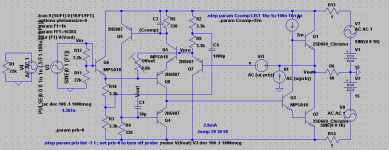
Another idea for offset correction: Run Q6 and Q7 at higher current, say 2x that of the NTP quiescent, and put a 50 ohm trimmer between the NTP emitters... Would be more susceptable to tempco of Q9 though.
Thanks for the clearer schematic, TVI.
R413 is a very clever way of correcting offset, but not super effective; the circuit is capacitively coupled so offset is not a problem.
Recap:
Here is a schematic from 4QDTec, where I first learned about the Rush Cascode/NTP. CFP's in class AB, good luck...
And here is the NAD 3020 phono preamp, same thing Gaetan posted last page but different image. It seems NAD has had an affinity for the Cascode.
I've also attached a schematic that increases PSRR without affecting performance.
- keantoken
Since it's faster, we can have more open loop gain without increasing compensation, as opposed to an LTP.
The prebuffers are set up in such a way that their Vbe decreases as the Rush Vbe's increase, but I haven't really measured this affect or determined its negligibility.
Another idea for offset correction: Run Q6 and Q7 at higher current, say 2x that of the NTP quiescent, and put a 50 ohm trimmer between the NTP emitters... Would be more susceptable to tempco of Q9 though.
Thanks for the clearer schematic, TVI.
R413 is a very clever way of correcting offset, but not super effective; the circuit is capacitively coupled so offset is not a problem.
Recap:
Here is a schematic from 4QDTec, where I first learned about the Rush Cascode/NTP. CFP's in class AB, good luck...
And here is the NAD 3020 phono preamp, same thing Gaetan posted last page but different image. It seems NAD has had an affinity for the Cascode.
I've also attached a schematic that increases PSRR without affecting performance.
- keantoken
Attachments
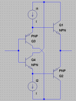
My NTP arrangement could also be seen as a series double LTP; Q8 and Q7 form an LTP, as do Q6 and Q5. There is also the possibility of using dual-packaged transistors here.
- keantoken
- keantoken
Alright, I've been thinking about the cautionary comments on the JLH output stage.
I was minding my business, and trying to work things out in sequence, when this thought rudely pushed its way through my frontal lobe.
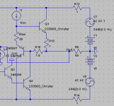
Q10 and Q1 form a current amplifier, which I gave a gain of 2 so that it would split up demand equally between Q1 and Q2.
And best of all, no strange harmonics.
R15 and R16 can probably be a reheostat. Adjust until waveform across them shows no trace of the fundamental.
- keantoken
I was minding my business, and trying to work things out in sequence, when this thought rudely pushed its way through my frontal lobe.
Q10 and Q1 form a current amplifier, which I gave a gain of 2 so that it would split up demand equally between Q1 and Q2.
And best of all, no strange harmonics.
R15 and R16 can probably be a reheostat. Adjust until waveform across them shows no trace of the fundamental.
- keantoken
Attachments
Last edited:
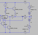
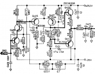
Here is one with gain. Adding gain decreases distortion. My fascination with the no gain version is that it cancels out almost all 3rd harmonics, leaving 2nd harmonics. I wonder what this sounds like (I have been told this harmonic profile sounds very good)).
I was told that adding emitter resistors would increase stability and help during input overload. Can't hurt...
D1 could be replaced with an NPN with base to Q1's emitter, making it an Allison output, but this didn't increase performance any.
The 3.4k resistors at top and bottom can be merged into a single 6.2k resistor for each leg.
- keantoken
Attachments
kt, what's the gain of this one? Will you give them names/version numbers or something?
I was set on building next a dht headphone amp but your circuit got my attention and since it's much simpler, I'll probably build it next if as soon as the GB is over. I'm very curious how it'd sound.
I was set on building next a dht headphone amp but your circuit got my attention and since it's much simpler, I'll probably build it next if as soon as the GB is over. I'm very curious how it'd sound.
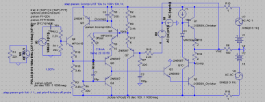
Gain is 10.
I was thinking about making the gain 3. Why would a headphone amp need any more than a gain of 3? Nothing wrong with having plenty to spare though.
I'll call the latest schematic version 2.1
And just so it has a name, I think I should call it "headrush".
So, Headrush version 2.1
- keantoken
I was thinking about making the gain 3. Why would a headphone amp need any more than a gain of 3? Nothing wrong with having plenty to spare though.
I'll call the latest schematic version 2.1
And just so it has a name, I think I should call it "headrush".
So, Headrush version 2.1
- keantoken
Congrats, you have basically re-invented the MJK anti-triode totem!
Mind, your quasi-depletion mode is different than I've seen before,
and maybe an improvement on prior art. Aleph and/or Half Allison
abuse an emitter reference turned backward here, but thats not
sayin it always works out better than emitter (and a diode) turned
the right way as you have.
The emitter of Q1 could bootstrap I1.
Last edited:
I think that it would be cool to have both versions, as this is enough for "most" headphoes but it seems that some headhpones might actually need a gain of 10.
Gain is 10.
I was thinking about making the gain 3. Why would a headphone amp need any more than a gain of 3? Nothing wrong with having plenty to spare though.
I'll call the latest schematic version 2.1
And just so it has a name, I think I should call it "headrush".
So, Headrush version 2.1
- keantoken
Kenpeter:
I prefer a transistor CCS, but I will probably go for bootstrap here since it's easier to build.
EDIT: actually, better bootstrap place is at Q10's base. Higher impedance this way and the phases work together to drive Q1's base.
Burgunder:
Changing the gain is easy, I could post schematics for every configuration.
- keantoken
Last edited:
OK... I like "headrush" , Let us build Headrush I . My head phone of choice are Koss Pro 4AA mainly because I own them since the last millenia. I have a Yamaha C4 Preamp that I use the headphone out that has a Moving coil head amp and I bought it new in 1978( I also have a Yamaha B2 amp , With small issues). I have an AR turntable with a Linn Basic Arm and a low mileage sony moving coil cartridge( the cartridge of origin was a Dynavector Ruby That needs retipping).
Help Me Out...Elwood
Help Me Out...Elwood
- Status
- Not open for further replies.
- Home
- Amplifiers
- Headphone Systems
- Rush Cascode Headphone Amp + JLH Output Stage