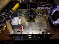
Just wired up the caps.
To clarify on the last post: something weird is going on and I think it may have to do with my scope. I was able to obtain some traces that matched the simulator, but I could turn the scope knob and the shape would change. Obviously that's not supposed to happen.
- keantoken
To clarify on the last post: something weird is going on and I think it may have to do with my scope. I was able to obtain some traces that matched the simulator, but I could turn the scope knob and the shape would change. Obviously that's not supposed to happen.
- keantoken
Attachments
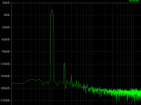
The trace was large until I flipped from 20mV to 10mV. Then the trace got small again (sounds like dirty switch contacts, but this didn't happen while testing directly with the signal generator). The time/div setting shouldn't matter. I tested at multiple frequencies and there was no indication of timebase problems.
- keantoken
- keantoken
kt, you around? Your latest is oscillating on me (ltspice). Would you like to exchange notes?
Here's my sim file.
Here's my sim file.
Last edited:
I'm still around, gathering up the courage...
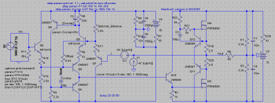
Figured out your problem, Iko, the compensation cap C1 isn't connected to anything on the node end. It should connect to Vout.
Also, your input voltage should not exceed the voltage across R15, or else the prebuffers/levelshifters and their sources will start switching.
- keantoken
Figured out your problem, Iko, the compensation cap C1 isn't connected to anything on the node end. It should connect to Vout.
Also, your input voltage should not exceed the voltage across R15, or else the prebuffers/levelshifters and their sources will start switching.
- keantoken
I'm still around, gathering up the courage...
Oh, come on! Just do it! Nike TM 🙂
Figured out your problem, Iko, the compensation cap C1 isn't connected to anything on the node end. It should connect to Vout.
Also, your input voltage should not exceed the voltage across R15, or else the prebuffers/levelshifters and their sources will start switching.
- keantoken
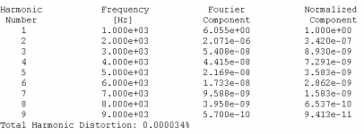
Oh, thanks. OK, now here's my nitpicking. Remember your earlier version that had H2 and almost no trace of H3? 😀 That I liked. This one, and in fact every one with gain, has some sizable H3. If you got some version with gain, and with only H2, that would be awesome! Whether it has mosfets or bipolars on the output isn't important to me.

I liked that version too, Iko. But the odd harmonics were there, they were just obscured by the noise floor. My recent changes were meant to make sure the even harmonics were audible.
They can be tuned out by matching the Vbe's of the level shifters. Note, that the NTP and amplifier mechanism itself generates practically no distortion; all the distortion is generated by the level shifters. Beyond that, the current through the level shifters should also be equal. (Note: I tried the simulation models of matched transistors and THAT arrays, but what we need for the level shifters are a matched NPN and PNP pair)
I've constructed a circuit on my breadboard for matching, but two transistors are showing 300mV difference at the same bias current of 15mA, and that can't be right. I'm not sure what's wrong but the diode function on my multimeter read them within 10mV. I don't think I'll trust breadboards ever again.
- keantoken
You can test this out by modifying the models. The 2N5087 and MPSA18 models get remarkably close in Vbe, which is just convenient for simulation. To get better matching, try varying Is in the models.
- keantoken
- keantoken
Well, I think I know the cause of at least one problem. We got a new computer recently along with a surge protector with battery backup... It says not to plug it in without a functionally grounded outlet, but guess what! *da da dum* Our house has no ground connection, which is certainly illegal, but we'd get thrown out for "renovations" if we did anything about it, so...
Anyways, I'm pretty sure it's injecting square wave trash into the AC lines, which doesn't bode well for measurements.
Still just a theory though, I will have to test it out later.
- keantoken
Anyways, I'm pretty sure it's injecting square wave trash into the AC lines, which doesn't bode well for measurements.
Still just a theory though, I will have to test it out later.
- keantoken
I liked that version too, Iko. But the odd harmonics were there, they were just obscured by the noise floor. My recent changes were meant to make sure the even harmonics were audible.
Wait, wait, wait 🙂 obscured by the noise floor means H3 is really small, and I wanted a listening test of that, but with gain.
They can be tuned out by matching the Vbe's of the level shifters. Note, that the NTP and amplifier mechanism itself generates practically no distortion; all the distortion is generated by the level shifters. Beyond that, the current through the level shifters should also be equal. (Note: I tried the simulation models of matched transistors and THAT arrays, but what we need for the level shifters are a matched NPN and PNP pair)
Doesn't sound very appealing.
I've constructed a circuit on my breadboard for matching, but two transistors are showing 300mV difference at the same bias current of 15mA, and that can't be right. I'm not sure what's wrong but the diode function on my multimeter read them within 10mV. I don't think I'll trust breadboards ever again.
- keantoken
Oh, yeah, breadboards, like those things that you stick wires into? Most are pretty bad. Gave that up long time ago, now I prototype air sculptures. What's soldered is soldered, end of story.
Weird "DC" readings that change with the touch of a finger are often a symptom of HF oscillation.Touching my finger to any spot instantly shifts the trace up several mV,...
Ditto.... but two transistors are showing 300mV difference ... and that can't be right ... my multimeter read them within 10mV....
[OT]Playing with little transmitter circuits, it's not unusual to have your multimeter tell you a transistor's BE junction is reverse biased, while it's conducting hard enough to get hot![/OT]
Don't mosfet's normally need gate stopper resistors for stability? - (tied directly to the gate pin, not via breadboard etc). Maybe that's a problem?
Last edited:
If that is the case, what is oscillating? This seems to be a new thing. Of course, I live right by an airport now.
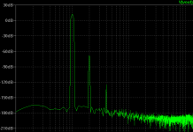
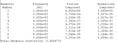
I think you're right Iko. I think this experiment of mine should end. Here is the original idea upgraded so it's "up to date". Even if the shifters aren't matched, odd harmonics should never go above even ones, so I guess it's a win-win. THD plots are the same as in the first post of this thread.
- keantoken
Attachments
Don't give up so easily. Put it on a back burner if you're tired of it now, and you'll solve it later. Research is like this. In my opinion you have a nice project going here.
Maybe the mosfets? 😕If that is the case, what is oscillating?
I haven't used them myself, but every mosfet power-amp circuit I've seen uses gate resistors to prevent oscillation...
edit: Don't you have experience with these things, Iko?
In kt's circuits I've seen the I/V probe that's used to sim the phase margin. I haven't looked at that yet for this circuit. In reality it's easy enough to stick a resistor on each gate. But if he doubts the breadboard he'll never be sure until he builds the circuit on copper or point-to-point. But hey, I'm not an EE.
kt, what I'm after is exploring the different distortion profiles. I mean personally that's a new thing for me, being a beginner and all that. So your circuit is very interesting to me because I might be able to use it in this exploration.
Told you already that your initial amp had a nice H2 and very small H3 and higher distortion. But to plug it into my phono stage it needs some gain, about 12dB would be nice. So I started with your initial circuit and added 12dB gain, then made two small changes to get it to distort as you can see below. First one with strong H2 and H4 but virtually no odd harmonic distortion. The second variation with smaller H2 but higher H3 distortion.
Edit: just want to explicitly mention that I'm not playing the "smallest distortion" game.
Attachments
Last edited:
My interests in the circuit are with the distortion profile too.
When you added gain, I'm willing to bet you also had to adjust the offset considerably. Using my above method this would change the balance of the shifters and H3 would increase. Try using the method in my first post in this thread; I think you will get better results.
Also, try changing the PNP level shifter into another transistor, so you can gauge for yourself the affects of Vbe imbalance (the MPSA18 and 5087 models are fairly well matched; the MPSA18 is used for high input impedance).
I think I'll build the simple version first, then I can modify it. Pity I still can't build a stereo version.
- keantoken
Last edited:
Why not stereo? Not enough parts?
Hey kt, the circuit (in general) seems very easy to get into oscillations. This isn't criticism, I'm just saying that IMHO one cannot expect to build the circuit with the exact values from the schematic and be 100% sure that it will not oscillate. I think the builder should expect to tweak the circuit until it is steady.
Edit: question for you. Do you trust your mpsa18 model?
Last edited:
I don't trust most models and I don't know what to expect in real life (I think I tested the MPSA18 though and it was reasonably close to the datasheet). I do know that using 33nF decoupling really helped oscillations on the breadboarded prototype.
Nope, not enough parts for a stereo build. Output stage resistors mainly. I'm using ancient 2.5 ohm Colber resistors I ripped off of some crossovers. I think if I had enough output resistors I could do a stereo build.
- keantoken
Nope, not enough parts for a stereo build. Output stage resistors mainly. I'm using ancient 2.5 ohm Colber resistors I ripped off of some crossovers. I think if I had enough output resistors I could do a stereo build.
- keantoken
Last edited:
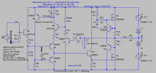
Here is what I'm about to build. The Balance resistor would be used to tune the "sound". Changing balance changes offset, but balance is fairly independent of offset (or just leave balance at 6.2k, it may not matter). So, adjust balance first and then worry about offset.
As you can see, rails are fairly low... I made an error computing the transformer voltages, but nothing devastating. Unfortunately it clips at -2V, but I don't think I'll need that much for my headphones.
- keantoken
As you can see, rails are fairly low... I made an error computing the transformer voltages, but nothing devastating. Unfortunately it clips at -2V, but I don't think I'll need that much for my headphones.
- keantoken
Attachments
Last edited:
- Status
- Not open for further replies.
- Home
- Amplifiers
- Headphone Systems
- Rush Cascode Headphone Amp + JLH Output Stage