@ florin
Honesty is also expensive for you.
There is nothing to clear out, cause we didn't discuss ever.
Also, the boards are fine as you can see on tibi's posts.
I put a period to such kind of discussions with all at once IDs.
Honesty is also expensive for you.
There is nothing to clear out, cause we didn't discuss ever.
Also, the boards are fine as you can see on tibi's posts.
I put a period to such kind of discussions with all at once IDs.
i want to sey sory if somebody engry for me. i have only this questions becoz i very need the source for my ipa400 modules. is expensive the price and for this money can bay toroidal transformator form petra, a good company who make this transformators for amplificators.
i dont now befor andy is same wit jegkraxi and is curios why he negate he spek with me before. i have the messenger logs to post for who dont beliv me.
i post also on elforum and ask the problem but my post is deleted everitime.
i am sory agan if i say someting bad, but peopl ned know what bay before give money and wait half year. if the situation is this i ask someboy to make for me the source. is one very gud boy in Timisoara which make sources wit gud price and he can make big one like 6KW.
Florin,
First, I suggest you to make a spelling check before posting.
Second, if you respect people of this forum, try to use uppercase letter when starting a new sentence.
I see that you have registered on:
Join Date7th January 2010Total Posts4
And all your posts are dedicated to our thread.
Well, I'm glad that this make such interest to you !
If you think that Petra make transformers for audio, than you are free to use them. Personally I'll strongly not recommend Petra for any audio product.
If you like to advertise on this thread, like few others, your friend 600KW SMPS, again I have no objection.
If you want to say that our SMPS is bad, Petra transformers are good, you are free to think so, but first try to build our SMPS and speak after.
Tibi
Last edited by a moderator:
I might ask if it's possible to reduce the voltage output to +/-43V? Also, how much current does this module produce? And is there a bill of materials? I'm a relatively inexperienced hobbyist and new to SMPS design, but I rather like the idea of not spending a fortune on a big power transformer.
Ok - let's go back to the main subject and learn more about the version II of this SMPS.
There are lots of people following the development of this project.
Thanks!
There are lots of people following the development of this project.
Thanks!
I do not think is relevant when I registered just why I registered on this forum just yesterday for me not to handle English as you already knew. I try to write correctly using direct translation not to motivate me to get laws.
It seems that you have to hide more things than I thought before since jumped up so hard when I ask you something. I wrote and a couple of minutes and no answer.
if everything is about respect for other members think would be best placed to answer your questions that were addressed related to the operation of the source and the current version. He is probably not interested in my answer emails neither you nor I asked Andy for too many questions about the source.
but as you know very bin accustomed to sell donuts to suckers like you did with the source before. every time someone asked for explanations and photos have jumped on it. were posted a few pictures of very poor quality that can not be seen if there is a source or a dead chicken. a dim bulb and a bunch of wires glued on the back panel where only you know. like that missing a handful of songs and want to believe someone that going? and I will praise the 1KW out? what kind of 1 KW? PMPO? chinezarie nothing else.
good guys who really know something and will give lessons at any time, see the type of Craiova and one in Timisoara who knows how to do source from 500W to 6 kW at good prices. if someone interested to make contact with him. 's and that guy who did it long ago that the source and put pictures and movies. All these were mocked, elongated and edited by those in positions of your gang, that bothers you and confused plans.
meanwhile I've decided to make a single source and you'll see that one come out stronger and cheaper than yours.
who wants to contact me to talk can do it peacefully. I do not have anything to hide. atantasiuflorin@yahoo.com
I might ask if it's possible to reduce the voltage output to +/-43V? Also, how much current does this module produce? And is there a bill of materials? I'm a relatively inexperienced hobbyist and new to SMPS design, but I rather like the idea of not spending a fortune on a big power transformer.
Yes, you can reduce to +/- 43V.
In fact, we have designed this SMPS to be able to output from +12V up to +350V and +/-6V up to +/-175V.
Two regulated voltages are available trough a separate SMD module.
The SMPS is able to deliver continuous 1KW with peaks at 1.2KW.
We can provide litzwire 120 x 0.1mm, high quality Epcos ETD 49 trafo and PWM module ready mounted.
BOM is available on this thread - post 71 - and here.
The BOM may be changed due the availability of components on different suppliers. I suggest to follow on this page as more info will be posted soon.
Regards,
Tibi
Last edited by a moderator:
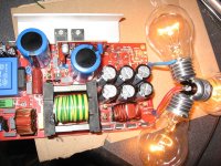
Maximum Load
Friend.
I think you should show us a 900W load connected to this supply for at least 8 hours, since its 1KW rated, what do you think?
It will handle that?
it will be good to post results in here also
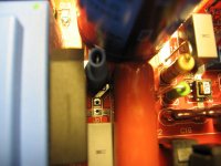
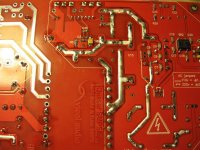
Bottom side of the SMPS and some more bulbs. 😀
If the main trafo is well made, the coppers will run cold.
Regards,
Tibi
Friend.
I think you should show us a 900W load connected to this supply for at least 8 hours, since its 1KW rated, what do you think?
It will handle that?
it will be good to post results in here also
Friend.
I think you should show us a 900W load connected to this supply for at least 8 hours, since its 1KW rated, what do you think?
It will handle that?
it will be good to post results in here also
Yes microsim444, I'll prepare and post here such measurements !
Regards,
Tibi
Few questions
I started assembling the SMPS and I have few questions:
1. The schematic V.2 contains some (I assume very important) comments. The problem is that they are in Romanian - translators like babylon do not translate them correctly - at least in some cases the translation does not make sense. Would it be possible to change the comments into English?
2. TR1 input filter - I cannot find a suitable filter with designed dimensions. Did you do it on your own?
3. TR3 is drawn on the schematic incorrectly - as 3+3 windings wheras I supose it should be rather 2+2. I also cannot find such a transformer with double primary windings which makes Jumper 2 useless. What is the desired output voltage of this transformer? Since you use it for +15V power supply, is it 2x7.5V or 2x9V? Can TEZ4/D/9-9 from TME be used?
4. Since there is a mistake on the board in the REMOTE module, can I just not solder Q3 and U1? I'm affraid that R6 and R7 are already soldered.
5. Should U6 (TL431) be mounted on the bottom or on the top or the PWM module? On some photos it was unclear. I think the initial version was on the bottom.
6. Should I change D11 and D12 in case I need higher voltages (e.g. 60, 70V)? I assume that output capacitors should be also changed. What abot the output transformer? Should it be changed too?
7. The problem with D13 is not clear (or rather the automatic translation is not clear). Do I understand it correctly that you can use two different types of diodes (and solder them differently)?
8. Can FR1J diode be used as D5, D6 (as it is specified in the BOM)? On the schematic they are listed as MURS120. Are both types correct?
9. Can you confirm that Rj1 is 1k and Rj2 is 0R? Their values are vot provided on the schematic (v.1) nor in BOM. I assume that Rj3 and Rj4 are 10R - they are also not listed in BOM.
10. Capacitors C6-9 are listed as 50V, 500V and 630V in various places. I assume that 500V is OK, right?
11. The problem with R12 is not clear - can you post a photo how it should be soldered?
12. Should TH1 be 5A? I think that I got 3A from Farnell which most probably is not enough.
Mark
Hi,
How do you mount a delicate and critical psu with all these errors?
I hope you do very carefully. High Voltage is no friend!
How do you mount a delicate and critical psu with all these errors?
I hope you do very carefully. High Voltage is no friend!
I hope that you red my post with understanding. It's hard to call problems with translations or difficulties with a transformer purchase an error. That's why I'm asking here to clarify them (problems) here. I asume that these problems are solved by the author of the project.
Mark
Mark
Few answers 🙂
1......
2. for TR1, use - WUERTH ELEKTRONIK|7448256033|CHOKE, COMMON MODE, 3.3MH 6A | Farnell România
3. The board provides various options in using TR3, including transformers like this one BLOCK|AVB3.2/2/9|TRANSFORMER, 3.2VA, 2 X 9V | Farnell România As I presume you have 220v mains, TEZ4/D/9-9 or TEZ4/D/15 are just perfect and Jp2 is useless. For TEZ.. 9-9 don't forget to connect pin 7 to pin 9 to obtain 18v on 6 - 10 pins.
4. The problem is solved if you don't solder Q3 and U1.
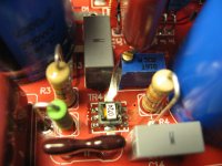
5. The U6 (TL431) should be mounted on the same side with IR2110, SG3525, etc. There is a footprint indicating the position of U6. Also, use this picture as a guide
6. Yes, you should change D11 and D12 for higher voltages; also, caps must support the output voltage 🙂. If you mean TR5, no changes are needed.
7. Also the aux module supports various options and one of them is to use a double diode, like FAIRCHILD SEMICONDUCTOR|MBR3045PT|DIODE, SCHOTTKY | Farnell România (for eg., 6v for tubes). Otherwise, "D13" represents 2 diodes, one for each line.
8. Yes, you can use FR1J diode as D5 & D6. Also, MURS120 is ok.
9. Yes, Rj1 is 1k, Rj2 is 0R and Rj3 and Rj4 are 10R.
10. Capacitors C6-9 are at least 500V.
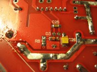
11. R12 is ok where the footprint indicates. For more stability, you should follow the trace from F1 (U5) to R32, cut it and place R12.
12. TH1 depends on the power that you want to be provided by your supply (P=220v * ...A) 🙂
Regards, Geani
1......
2. for TR1, use - WUERTH ELEKTRONIK|7448256033|CHOKE, COMMON MODE, 3.3MH 6A | Farnell România
3. The board provides various options in using TR3, including transformers like this one BLOCK|AVB3.2/2/9|TRANSFORMER, 3.2VA, 2 X 9V | Farnell România As I presume you have 220v mains, TEZ4/D/9-9 or TEZ4/D/15 are just perfect and Jp2 is useless. For TEZ.. 9-9 don't forget to connect pin 7 to pin 9 to obtain 18v on 6 - 10 pins.
4. The problem is solved if you don't solder Q3 and U1.
5. The U6 (TL431) should be mounted on the same side with IR2110, SG3525, etc. There is a footprint indicating the position of U6. Also, use this picture as a guide
An externally hosted image should be here but it was not working when we last tested it.
6. Yes, you should change D11 and D12 for higher voltages; also, caps must support the output voltage 🙂. If you mean TR5, no changes are needed.
7. Also the aux module supports various options and one of them is to use a double diode, like FAIRCHILD SEMICONDUCTOR|MBR3045PT|DIODE, SCHOTTKY | Farnell România (for eg., 6v for tubes). Otherwise, "D13" represents 2 diodes, one for each line.
8. Yes, you can use FR1J diode as D5 & D6. Also, MURS120 is ok.
9. Yes, Rj1 is 1k, Rj2 is 0R and Rj3 and Rj4 are 10R.
10. Capacitors C6-9 are at least 500V.
11. R12 is ok where the footprint indicates. For more stability, you should follow the trace from F1 (U5) to R32, cut it and place R12.
12. TH1 depends on the power that you want to be provided by your supply (P=220v * ...A) 🙂
Regards, Geani
Last edited:
Hello Mark,
1. Yes. Please address any concerns or issues you may have here and I'll do my best to answer.
2. You are referring to physical dimensions? Some components we have been purchased from a local distributor, but mainly these are from TME and Farnell. Seems that Tr1, made by Wurth Electronik , is no longer available on Farnell. I'll search for an substitute and let you know.
3. Yes, you are right. The trafo we use is 2+2.
You can use TEZ4/D/9-9 from TME, or TEZ4/D/15V which was indicated in BOM.
4. REMOTE was designed to work ONLY with DanZup volume controller, and provide stand-by control from an RC5 IR. It is recommended do not mount that parts for this option. Therefore I advice you do not solder Q3 and U1.
5. U6 (TL431) must be mounted on the top where the component footprint is painted on pcb.
6. You can change D11 and D12, without any other modifications on trafo up to +/-70V. D11+D12 will give output voltage/2 with +/-1V approximation. Take care of this.
7. D13 is a combination on a double diode and a single diode.
ie: double BYV72 and single BYV79
8. As replacement of schematic components, FR1J diode can be used as D4, D5, D6 with very good performance.
9. Yes, I confirm that Rj1 is 1k and Rj2 is 0R.
10. C6-C9 are bridge decoupling capacitors ceramic X7R at 500V.
11. See below picture - red square.
12. Th1 must be at least 5A
Regards,
Tibi
Attachments

Last edited by a moderator:
Thanks guys,
This clarifies most of the problems. However, few are still unclear.
Regards,
Mark
This clarifies most of the problems. However, few are still unclear.
It seems that TEZ4/D/15V indicated in BOM is not correct. It has only single windings and the secondary winding is connected to pins 7 and 9. It should be rather connected to 6-7 and 9-10 if I remember correctly (I don't have the board here with me)....
3. Yes, you are right. The trafo we use is 2+2.
You can use TEZ4/D/9-9 from TME, or TEZ4/D/15V which was indicated in BOM.
Ha, ha. And the picture you attached shows just the oposite 😀. I guess it just doesn't matter.5. U6 (TL431) must be mounted on the top where the component footprint is painted on pcb.
This brings me back to my remark #1 - remarks in Romanian on the schematic. I don't understand it. Are you saying that the diodes are exactly as indicated on the schematic or there should be some modification?7. D13 is a combination on a double diode and a single diode.
ie: double BYV72 and single BYV79
Regards,
Mark
One more problem.
13. I learned that the components marked green in the BOM are for tube version. C38-43 (2200uF/63V) are also marked green but I think that they are for SS version. Aren't C58-59 (470uF/400V) for tube version?
Mark
13. I learned that the components marked green in the BOM are for tube version. C38-43 (2200uF/63V) are also marked green but I think that they are for SS version. Aren't C58-59 (470uF/400V) for tube version?
Mark
- Home
- Amplifiers
- Power Supplies
- ±50V SMPS for Quasar Amps (& others)