The claim to fame of the 1837/4793 are their speed for drivers - 100MHz. But the outputs are much slower than this - what, 20 to 30 MHz? 4MHz even? So maybe they were just "too fast".
I don't think they are bad, but rather, sometimes superfast japanese transistors and slower ONSemi types don't work well together.
Could you experiment a little more with the Allison compensation? There is a 10nF cap, then the 560 ohm resistors are still there (are they?)... Can you see which compensation caps are most important? I suspect that removing the 10nF cap will have a large affect. I'm interested here because the 100pF caps and 560 ohm resistors have the largest affect on THD20. If the distortion at this level is audible (many say it isn't), then reducing it should make the sound less "bright".
Thanks for your work,
- keantoken
Keantoken,
Yes the 10nf cap and 560 ohm resistor are still in place. I figured without the 100pf cap the resistor isn't forming any sort of filter, ( it is did drive the bais voltage up about 100mv) so, probably isn't having any effect. I'll pull it out and then the 10nf and see what happens.
Regarding the 1837/4793 I believe MJL used them in his Patchwork amp driving Onsemi's maybe not, tough to look this stuff up while writing...
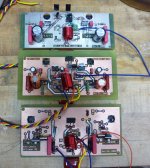
Now I have three working outputs driven by the LME49811. Which one to choose? I played the Allison Class A/B (Paul's scheme) all day today, the sound is very nice! (and it doesn't need the window fan blowing on it to keep things cool.
Ken L
You're right, the 560 ohm resistors shouldn't have much of an affect and most engineers probably wouldn't bother messing with them. I don't have much experience so in my mind there is no due process and they're guilty until proven innocent... (the difference is whether Cob has an ESR of 0 ohm or 560 ohms)
The fast drivers might not have an affect in all situations. In the Allison, however, they are put inside an ultrafast high-OLG feedback loop.
Which one you choose is up to you... Follow your ears, I presume? The class A Allison should have the least distortion but if you can't tell the difference, why not go green with the Schottkey AB mod? I await your decision, and if possible could you describe the differences in sound?
- keantoken
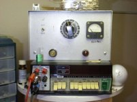
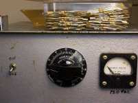
Oh, and I have a new addition to my bench... Found it lonely and dejected a WWII antique store no less (don't know if it's really that old though)! It had some bad contact areas on the coil, and I worried there may be some shorts but I went around the contact area with sandpaper and oil, and after several times it's smooth from start to finish. Nothing wrong with it in the first place apparently. The seller mentioned having used it himself.
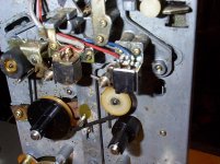
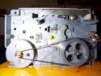
My grandma threw out the cassette player which apparently didn't work. It's built like a tank, and in fact uses oddly packaged transistors, germanium possibly. Old but the belt is fine. I figure I can make my own cassette player, and I want to see how good cassettes can sound. I've oiled all the bushings and bearings, including oiling somethings which I later discovered should not be oiled! When the day was done, I played some tapes through my oscilloscope's "signal out" jack, not the best source but hey...
Just because I KNOW everyone LOVES pictures, they must when staring at this bleak wall of text and lines all day...
Not to interrupt, this is just a small break... More pictures coming.
- keantoken
Attachments

Last edited:
Okay, some topical information...
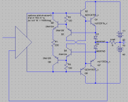
Klewis, if you want to take it one step further, might I suggest you try something like this...
I don't think the Allison can be any more class B than this! I don't think there are any benefits distortion-wise though. One possibility is that you have complete control of the bias current, so you can attach a knob to change it from class A to class B...
Complete control of the bias is done by the emitter resistor(s) of Q5 and Q6.
However, is there really a point to a class B or AB Allison? Does it perform any better than a simple Vbe multiplier with schottkeys on the emitters?
- keantoken
Attachments
Okay, some topical information...
However, is there really a point to a class B or AB Allison? Does it perform any better than a simple Vbe multiplier with schottkeys on the emitters?
- keantoken
Keantoken,
I'm adding this one to the list. Thanks for thinking about it. No emitter resistors required?
As to your question, that's what I'm attempting to find out. One benefit that I see is having the amp staying in Class A initially and getting the (hopefully) sonic benefits of Class A without having a heater.
I figures out how to get my sound card working correctly, need to set RMAA to mono mode, background THD for the card is now .0045. First measurement of the Allison ClassA version with the 100pf caps removed but 560 ohm resistors still in place was .05 THD. More measurements to come.
I have two Turtle Beach sound cards, Keantoken, you have a PC, do you have a sound card for measurements?
Ken L
Last edited:
I have a Creative x-fi, not what most would recommend, but it has good numbers when you disable all the "features".
However, I would recommend something like the M-audio 2496, which many would recommend.
My next sound card will probably be this:
ESI Juli@ – Professional Sound Card
The killer looks, the nifty PCB... I haven't kept up with the technology but from what I've heard it it has numbers that compare.
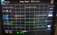
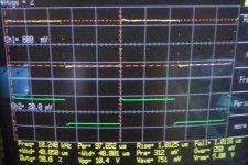
The .05%THD for the Allison, I think is alarming. I would expect it to be much lower... So maybe there is a grounding problem or something? After all the great simulations, this is not expected (but they're only simulations really). (if you can, could you post scope shots of the voltage across R1 in my schematic with a sine source? I still don't know if the LME49811 outputs are balanced or one is simply a CCS, and this would be revealing. Hopefully it's balanced, which means it is optimal for the Allison, a perfect marriage between chip and discrete!)
I didn't simulate the new version with resistors in series with the diodes, if that's what you mean by emitter resistors. I'm not sure what affect these resistors would have. They might lower distortion but they could at the same time make it less class B, meaning you would need higher bias current...
- keantoken
However, I would recommend something like the M-audio 2496, which many would recommend.
My next sound card will probably be this:
ESI Juli@ – Professional Sound Card
The killer looks, the nifty PCB... I haven't kept up with the technology but from what I've heard it it has numbers that compare.
The .05%THD for the Allison, I think is alarming. I would expect it to be much lower... So maybe there is a grounding problem or something? After all the great simulations, this is not expected (but they're only simulations really). (if you can, could you post scope shots of the voltage across R1 in my schematic with a sine source? I still don't know if the LME49811 outputs are balanced or one is simply a CCS, and this would be revealing. Hopefully it's balanced, which means it is optimal for the Allison, a perfect marriage between chip and discrete!)
I didn't simulate the new version with resistors in series with the diodes, if that's what you mean by emitter resistors. I'm not sure what affect these resistors would have. They might lower distortion but they could at the same time make it less class B, meaning you would need higher bias current...
- keantoken
Last edited:
Well, what you can do with the circuit I gave is "turn it up" into class A any time you want, although it will still have distortion because of the diodes. Heck, you could even give it a "temperature" knob attached to a thermostat controlling the bias... You could impress your friends by "going green" with the push of a button!
- keantoken
- keantoken
R1 (in the second schematic) should not go below 100 ohms, or below the point where it is completely class B at least, because too low a value could cause the bias voltage to become negative dependeing on the Allison Vbe's, which is really a problem.
The 560/100pF compensation should be applied the same way to this version, on the bases of Q3 and Q4. I breadboarded this version once, I think it is actually more stable than the normal Allison... I wonder what your results will be, and thanks for trying it out.
- keantoken
The 560/100pF compensation should be applied the same way to this version, on the bases of Q3 and Q4. I breadboarded this version once, I think it is actually more stable than the normal Allison... I wonder what your results will be, and thanks for trying it out.
- keantoken
Last edited:
The .05%THD for the Allison, I think is alarming. I would expect it to be much lower... So maybe there is a grounding problem or something? After all the great simulations, this is not expected (but they're only simulations really). (if you can, could you post scope shots of the voltage across R1 in my schematic with a sine source? You mean R1 from post 266? I'll put the probe on one side of R1 and ground on the other - yes.I still don't know if the LME49811 outputs are balanced or one is simply a CCS, and this would be revealing. Hopefully it's balanced, which means it is optimal for the Allison, a perfect marriage between chip and discrete!)
- keantoken
I didn't simulate the new version with resistors in series with the diodes, if that's what you mean by emitter resistors. I'm not sure what affect these resistors would have. They might lower distortion but they could at the same time make it less class B, meaning you would need higher bias current...
- keantoken
In Paul's scheme he has emitter resistors in series with the Schotki (.1 ohm).
Ken
I meant the second schematic in post 386. But by putting the ground end there aren't you effectively shorting the circuit to ground?
I don't think the .1 ohm resistors are necessary in my scheme. They were necessary in Paul's to lower the bias current down to a reasonable level when there was no fixed bias voltage.
- keantoken
I don't think the .1 ohm resistors are necessary in my scheme. They were necessary in Paul's to lower the bias current down to a reasonable level when there was no fixed bias voltage.
- keantoken
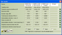
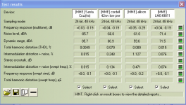
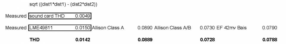
So things are quite so bad 🙂. I was using aligator clips as a part of the measurement aparatus, things started getting weird, so, I measure the resistance of the clip/wire combo - off the charts. Don't know why they degraded, but, I fixed them up with some trimming and solder. New measurements attached. The calcualtion sheet discounts the sound card.
Note: the "Allison A-B" scheme still has the compensation capacitors in place, the "Allison" has the compensation capacitors/resistors (100pf/560ohm) removed.
Lots of graphs and numbers to follow.
Ken L
Note: the "Allison A-B" scheme still has the compensation capacitors in place, the "Allison" has the compensation capacitors/resistors (100pf/560ohm) removed.
Lots of graphs and numbers to follow.
Ken L
Attachments

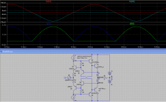
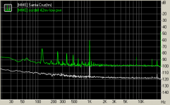
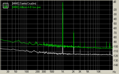
For comparison here's the EF output compared to the allison A/B scheme also the allison class A scheme, remember, with compensation removed.
Ken L
Ken L
Attachments
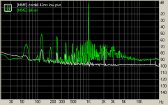
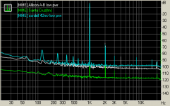
Can you subtract the soundcard spectrum from the Allison spectrum so we can see the specific harmonics? Whether they are mainly 2nd or 3rd order would help us determine which mechanisms of distortion were in play... Oddly enough, it seems the Allison is creating dominant even harmonics, which is odd and would indicate something strange.
And at what power output is this?
And, the class A Allison's spectrum is simply too odd... Why not put compensation back in and see if it reads the same? The 60Hz harmonics also suggest a grounding error or EMI of some kind. (or, perhaps, there was resampling or some soundcard goof?)
Also, why is the Cordell measured at only -60db? This makes it not comparable, because it will certainly perform better at lower volumes.
Or maybe a Wizard will come along and shed some understanding on me... I haven't made any measurements with RMAA so I can't tell exactly what's happening.
- keantoken
Can you subtract the soundcard spectrum from the Allison spectrum so we can see the specific harmonics?I don't think so, haven't seen anyone else do this either - a couple of things, the spike at 1kHz is an artifact of the RMAA and to be ignored, other wise, I visually compare the sound card to DUT. Whether they are mainly 2nd or 3rd order would help us determine which mechanisms of distortion were in play... Oddly enough, it seems the Allison is creating dominant even harmonics, which is odd and would indicate something strange.
And at what power output is this? I have no idea 😱 I guess I could put a voltage meter on the sound card output, but, it seems to cycle through a bunch of measurements, so, I don't know if I would be measuring the voltage at the time of the THD analysis. As you said, maybe a sage with come along and help.
And, the class A Allison's spectrum is simply too odd... Why not put compensation back in and see if it reads the same? The 60Hz harmonics also suggest a grounding error or EMI of some kind. (or, perhaps, there was resampling or some soundcard goof?)
Also, why is the Cordell measured at only -60db? I take some of these numbers with a grain of salt - view them as relative to one another. Also, my measurement set up isn't very clean, I need to put some effort into getting it in order, hopefully will bring the DUT numbers down across the board.This makes it not comparable, because it will certainly perform better at lower volumes.
Or maybe a Wizard will come along and shed some understanding on me... I haven't made any measurements with RMAA so I can't tell exactly what's happening.
- keantoken
Last edited:
Okay, some topical information...
Klewis, if you want to take it one step further, might I suggest you try something like this...
I don't think the Allison can be any more class B than this! I don't think there are any benefits distortion-wise though. One possibility is that you have complete control of the bias current, so you can attach a knob to change it from class A to class B...
Complete control of the bias is done by the emitter resistor(s) of Q5 and Q6.
However, is there really a point to a class B or AB Allison? Does it perform any better than a simple Vbe multiplier with schottkeys on the emitters?
- keantoken
What did your THD numbers look like? This version isn't within the LME49811 feedback loop - If the THD numbers are good even with the diodes in the circuit, that would be a good thing. I could try within and outside the feedback loop.
Ken L
Yes, having the Allison outside the feedback loop could do it. I would consider this necessary for the class B/AB versions.
THD was always below .01% in my simulations, but this depends a lot on the source impedance.
Also, please make the RMAA measurments at the same levels. This would entail turning the amp volume (not soundcard volume) up until the RMAA meter reads 1db. This is to keep the noise floor as low as possible without overdriving the soundcard.
- keantoken
For the Class B/AB version (Paul's scheme) the Allison is within the feedback loop.Yes, having the Allison outside the feedback loop could do it. I would consider this necessary for the class B/AB versions.
THD was always below .01% in my simulations, but this depends a lot on the source impedance.
Also, please make the RMAA measurments at the same levels. This would entail turning the amp volume (not soundcard volume) up until the RMAA meter reads 1db. This is to keep the noise floor as low as possible without overdriving the soundcard.
- keantoken
The RMAA measurements for the three amps were all at the same level, the sound card test was at a different level. The amp doesn't have a volume control. Only way to set the volume is via the sound card line in and line out controls. You need to set the volume or line in until the meter show approx. -2db. When doing this, it give you a preview. I mess with the line in and line out to minimize the noise floor, then save it as my test level for all these amp tests. I guess I could run the card test through my preamp to bring it's volume up to better normalize the test - the pre amp tested at the noise floor of my prior sound card which was .00019 (may it rest in peace). You can download RMAA for free at Right Mark Audio Analyzer. The only trick is under the sound card, put a check mark in the mono mode.
To Paul,
If you are still following along, I still haven't measured the voltage climb across the diodes, but, note that the diodes never even get warm, I check them after testing into 8ohm load.
I'm working on a new LME49811 output board that will have jumper to try out the different combinations of compensation you suggested.
Then onto Keantoken's Class A/B scheme.
To All,
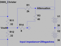
One last question, for full power test of the amp without cooking the sound card I'm planning on an attenuation scheme of line out to 2k with 40r to ground. I've simulated this and it seems to give plenty of attenuation. Does this make sense? I'm planning on using 5 10k 1watt || for the 2k and 5 200r 1watt || for the 40 ohm. Using CMF60 to keep the noise down.
Ken L
Attachments
- Home
- Amplifiers
- Solid State
- Simulation Analysis of several unique Allison-based output stages.