Hi Rod,
Thank you once again for the excellent advice, I should be able to squeeze it into the preamp chassis.
Do you think it would be beneficial to mount all the parts for this circuit (except the big cap) in a small sealed aluminium diecast box (also using it as a heatsink) and have leads out for the tube filament and voltage in?
As for cathode resistor position, I’m using the centre tap of 2, 20ohm resistors. Looking at a lot of the data sheets I’m at a loss as to which filament pin is the +and the -. Can anyone enlighten me?
Arnulf, It’s a pity you may have a bad batch of LM350’s. I just measured the mounting tabs thickness of my Fairchild LM 350T at 1.34mm and the LT1086 at 1.26mm. Perhaps the T version is a bit more robust.
Cheers,
Rich
Rich, sometimes the valve data sheet indicates a +ve/-ve filament terminal, others not.
If not indication given, the negative is the one that returns to the filament -ve supply. connect this one to the cathode resistor (and capacitor, if used).
I would try both terminals and see if the sound changes!
Don't use a centre-tapped resistor for CCS heated amps. The resistor will rob current, and may degrade the sound too.
I would be careful of sealing a 1A transformer in a box. may overheat
I prefer the transformer AND rectifier/caps away from the whole amp, since there are wide-bandwidth magnetic field pulses around from the cap charges and recovery pulses. These are not easy to shield without thick (12mm Alu) chunks of metal.
I prefer the transformer AND rectifier/caps away from the whole amp, since there are wide-bandwidth magnetic field pulses around from the cap charges and recovery pulses. These are not easy to shield without thick (12mm Alu) chunks of metal.
but LTspice won't simulate without a ground
Rod,
I am fully aware of that🙂. Was more thinking of the others in this thread, not being LTspice users.
Isn´t 5,5V a little lean?
We did a std heater-CCS for 6B4G a while ago and found that good regulation didn´t, for some reason, occur for the 1084 until it had in the ballpark of 5V including resistor over it.
Also simmed the regulatorwith added ripple and it pointed in the same direction.
Don´t know how much your MOSFET needs over it, but this points to a total of maybe 10V?.
Must sim when I get home.
Rod,
Isn´t 5,5V a little lean?
We did a std heater-CCS for 6B4G a while ago and found that good regulation didn´t, for some reason, occur for the 1084 until it had in the ballpark of 5V including resistor over it.
Also simmed the regulatorwith added ripple and it pointed in the same direction.
Don´t know how much your MOSFET needs over it, but this points to a total of maybe 10V?.
Must sim when I get home.
Lars, You may be right. If the chip is not getting adequate voltage headrooom, its current source characteristic will be degraded.
At 1A, ordinary FETs will lose 4 to 5V, "logic level" types 2,5 to 3V
10V is probably a good idea.
Thanks Rod, I'll take those resistors out.
Sorry, I may not have been clear with my question, I was referring to just the parts of the gyrator (the 1086, fet, resistors and 5uF cap). I have the transformer and big caps about a meter away.
Rich out
I would be careful of sealing a 1A transformer in a box. may overheat
Sorry, I may not have been clear with my question, I was referring to just the parts of the gyrator (the 1086, fet, resistors and 5uF cap). I have the transformer and big caps about a meter away.
Rich out
Rod,
Home at my lunch-hour simming when the rice is getting cooked.
Have tried some randomly chosen MOSFETs from the LTspice library. Most of them are over 5.5V!
So if this is correct probably 10-12V is needed.
Will try to find a model of the one you recommended.
Anyway great idea with the gyrator and current sink!
Rod,
Found the STP55..... It sims with just below 2V over it. Got the model from STM and checking their datasheet it seems right. Can you confirm this is correct IRL? Then only 8V would be needed.
Found the STP55..... It sims with just below 2V over it. Got the model from STM and checking their datasheet it seems right. Can you confirm this is correct IRL? Then only 8V would be needed.
Thanks Rod, I'll take those resistors out.
Sorry, I may not have been clear with my question, I was referring to just the parts of the gyrator (the 1086, fet, resistors and 5uF cap). I have the transformer and big caps about a meter away.
Rich out
Rich, can box the Gyr/CCS if preferred. I haven't tried this.
1m clearance for the trafo/rectifier/caps should be perfect.
Arnulf, It’s a pity you may have a bad batch of LM350’s. I just measured the mounting tabs thickness of my Fairchild LM 350T at 1.34mm and the LT1086 at 1.26mm. Perhaps the T version is a bit more robust.
I checked the part once again just to make sure: it is a LM350T with F logo and J43 on the right hand side of the logo. I believe this is Farnell item #1417673 although I don't have the receipt anywhere handy. I'm beginning to wonder if this is really a Fairchild part, regardless of what Farnell claims - Fairchild's datasheet specifies tab width to be more than twice of what I've just measured.
Tab thickness is 0.6 mm (in comparison to 1.36 mm of a Motorola-branded LM337 I had lying around). 1.3-1.4 mm seems the norm for any other TO-220 component I can find.
Anyway, stay clear of the parts with thin tab if you don't want to end up 😡 like me

I checked the part once again just to make sure: it is a LM350T with F logo and J43 on the right hand side of the logo. I believe this is Farnell item #1417673 although I don't have the receipt anywhere handy. I'm beginning to wonder if this is really a Fairchild part, regardless of what Farnell claims - Fairchild's datasheet specifies tab width to be more than twice of what I've just measured.
If Farnell sent that to me, I'd return it.
It sounds too much like one of the fake semis we hear about.
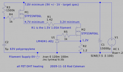
If the LT108x needs 5V of headroom to perform properly, we can improve on that.
This circuit uses the same FET in both positions, plus a 3-pin 1,2V reference chip.
If you use the exact parts noted on the drawing, it should work with supplies down to 7V. But you will want to work with real supplies with a tolerance, and some ripple: so 9V +/- 1V should be just right, and allow the use of 10V filter capacitors.
These parts are all very cheap, especially at Rapid:
LM4041
Integrated Circuits from Rapid
STP55NF06L
Rapid Electronics - Electronic Components > Semiconductors
Attachments
Couple of things in this great thread!
With the 300b I fed the LM1084 ccs from a variable bench supply and it seemed to regulate from about 8v. So I reckon on minimum of 3v headroom.
For the power supply box, I use an umbilical a metre long to the signal chassis. It's fixed at the power supply end. I use a Speakon 4 pin for the HT if it's under 350v and a Amphenol AP series 4 pin if it's higher voltage than 400v. I use XLR 4 pin as a rule for the preamp heaters. I put the flament transformer and the diodes in the PSU box, and the 15,000uF cap and the rest of it in the signal chassis. for the HT I put the mains transformer, rectifier, choke and reservoir cap in the PSU box and then a glow tube or actually two glow tubes giving 255v in the signal chassis. So only DC goes to the preamp.
andy
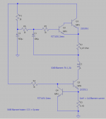
Thanks very much Rod for posting that! Did a search of the fzt1051 and it is surface mount. Do they have through hole stuff? And how well did you have to heatsink those parts?Bas, This is the known-good sounding 300B heater I have used for the past 5 years
Bas, This is the known-good sounding 300B heater I have used for the past 5 years.
It only controls current, and has no voltage control. Even so, it still delivers 4.91V, 5 years after its last set-up.
Rod, simple and elegant design. 😎 I am sure this circuit has much better drop out performance than the typical monolithic, amongst other things. I think I will give this a try in one of my next amplifier projects. Hmm, maybe a respin for a GM70.. Thanks.. 😀
If Farnell sent that to me, I'd return it.
It sounds too much like one of the fake semis we hear about.
It's not worth the cost of shipping them back.
The regulators work, they just suck as far as cooling is concerned, they simply cannot move the heat away from the silicon fast enough so they keep shutting down. I thought big distributors such as Farnell have their own QC and don't deal with fakes. I've bought numerous components from eBay and never encountered a fake.
Thanks very much Rod for posting that! Did a search of the fzt1051 and it is surface mount. Do they have through hole stuff? And how well did you have to heatsink those parts?
manufacturer Zetex (Diodes inc) ZTX868 is probably nearest equivalent.
I imagine the BC547C would work OK too.
With the 300b I fed the LM1084 ccs from a variable bench supply and it seemed to regulate from about 8v. So I reckon on minimum of 3v headroom.
Andy,
As mentioned earlier the 1084 regulates with 3V. Still you need ca 5V headroom to get good regulation when used as CCS.
Don´t mind my message to you. I have got the 26´s I need.
Couple of things in this great thread!
For the power supply box, I use an umbilical a metre long to the signal chassis. It's fixed at the power supply end. I use a Speakon 4 pin for the HT if it's under 350v and a Amphenol AP series 4 pin if it's higher voltage than 400v. I use XLR 4 pin as a rule for the preamp heaters. I put the flament transformer and the diodes in the PSU box, and the 15,000uF cap and the rest of it in the signal chassis. for the HT I put the mains transformer, rectifier, choke and reservoir cap in the PSU box and then a glow tube or actually two glow tubes giving 255v in the signal chassis. So only DC goes to the preamp.
andy
Andy, I think the umbilical idea is perfect.
Have you tried locating the caps right up close to the transformer? I try to keep the wiring between the rectifier and caps (and the trafo) as short as possible, because the CURRENT running along those wires is a pulse train of 2 to 5A peak, with fast rise time and high-band recovery pulses (even with schottkys!). With long wires there is a risk of electromagnetic coupling into the amp.
- Home
- Amplifiers
- Tubes / Valves
- #26 pre amp