The thermal instability of the parallelled mosfets is likely to be enough to ensure that, even without the cumbersome need of short-circuiting the amplifier output.
Michael,
you seem to be oddly fascinated by this evidently average design. Do you intend to build it? Hopefully, you have moderate expectations on sonic performance, which can position itself quite a bit below mediocre. (With some luck).
you seem to be oddly fascinated by this evidently average design. Do you intend to build it? Hopefully, you have moderate expectations on sonic performance, which can position itself quite a bit below mediocre. (With some luck).
Federmann,
just of curiosity can you tell us what is the current through transistors T107 and T108?
And what are the resistor values of R114 and R115?
Thank you!
Cheers Michael
Streams will be higher as 50 milliamperes. Resistances smaller as 100Ω. Exactly will be decided by transistor. According to measurements based on zener diodes is less than 5V. Everything will be specified for each module individually.
Streams will be higher as 50 milliamperes. Resistances smaller as 100Ω. Exactly will be decided by transistor. According to measurements based on zener diodes is less than 5V. Everything will be specified for each module individually.
Thank you Federmann,
are you going to use the popular high performance VAS transistors Sanyo 2SA1540/2SC3955 or Toshiba 2SA1360/2SC3423 for your T107 and T108, the aforementioned transistors are virtually the very best one can find these days.
Lumba Ogir,
I bet you would be jealous if I would build Federmanns 1kW amp because it would smoke you out literally!
Attachments

Last edited:
 Nothing, if that's all you do. I've trimmed out some rather intemperate personal attacks. Please keep it to technical discussion.
Thank you Federmann,
are you going to use the popular high performance VAS transistors Sanyo 2SA1540/2SC3955 or Toshiba 2SA1360/2SC3423 for your T107 and T108, the aforementioned transistors are virtually the very best one can find these days.
I use 2SC2238B/2SA968B have higher voltage and power.

simulations are no answer. Replacing a 'mind only' by a 'simulation only' design has some 'smell' too.
regards
regards
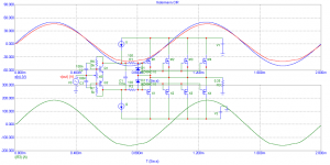
I hope images would say more than words. 50 amperes per device, exactly as said by BV. Models are 240 nad 9240.
An externally hosted image should be here but it was not working when we last tested it.
Your involvement is not even my involvement, I wonder why submit the involvement of entirely different?
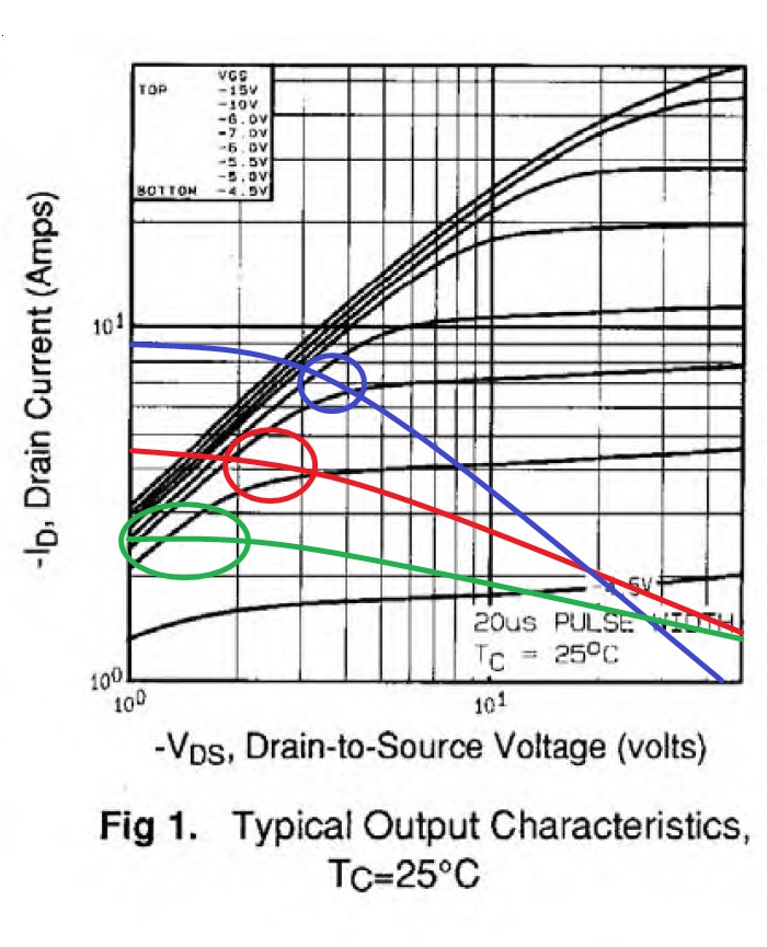
Please look at what's over those colored circles in the text written on each diode in my text.
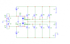
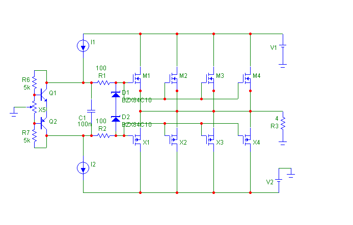
Current 'limitation' of the Federmann's output stage, load 0.25 ohm :
It is the same output stage, same 'protection' by 10V zeners. Wire from midpoint of zeners already added, regardless that there is no current limitation in any safe area.
Attachments

It is the same output stage, same 'protection' by 10V zeners. Wire from midpoint of zeners already added, regardless that there is no current limitation in any safe area.
Why you do not read text and write what the text is not?
Quote:
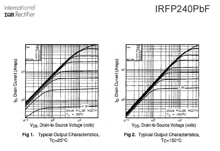
„Chceme-li dosáhnout u tranzistoru IRFP9240PbF saturačního napětí v rozmezí 2÷3V a zároveň proudové omezení v rozmezí 4÷4,5A, použijeme omezení napětí UGS v rozmezí 5,1÷5,4V. V tomto pracovním bodě je vhodné spojované tranzistory překontrolovat. Obdobné hodnoty vyjdou pro saturaci v jiném pracovním bodě.“
"If we want to bring the transistor IRFP9240PbF saturation voltage in the range of 2 ÷ 3V while current restrictions in the range of 4 ÷ 4,5 A, will use UGS limited voltage range 5.1 ÷ 5.4 V. At this point it is appropriate to the work associated transistors check. Similar values come to work in a saturation point. "
Here is why it will not work well without source resistors. Let's look at Vgs = 4.5V and Vds > 10V. In that case, the drain current is:
For temperature = 25 Celsius, it is Ids = 0.6A.
For temperature = 150 Celsius, it is Ids = 25A.
That is not a reduction in current with increased temperature!
All the parallelled transistors have the same Vgs so the hottest one will work harder than the others. Drawing a load line and pointing at it is nonsense. It is current sharing that is the problem, nothing to do with the load line.
However, the BUZ9** transistors you mention on your page do not have this problem. They can be parallelled just fine without resistors.
Thanks but I new this in 82, from "Analysis and Design of Analog Integrated Circuits" Gray and Meyer (1977).
What I wanted to know was Federmanns reason, which he just explained: If I understand correctly more gain at input = less stages = less phase shift. Dont know if I totally agree. I see it like this: "the linear range of operation is extende by an amount approximately equal to IeexRe. The voltage gain is reduced by approximatley the same factor" . In a feedback amp if you decrease the open loop gain, you increase the diff input voltage, so the gain and the linearity of the input diff pair become more complicated in a feedback loop. I have read Selfs book but dont remember him mentioning this(maybe I missed it. (And increasing the gm by increasing Iee is fairly limited by the transistor beta/Ic linearity)
You understand exactly. I care about the overall importance of repayment feedback. Therefore, I do not want any local feedback, which is moving in profit. Linearity is then given the linearity of elements, but the margin of profit.
Nice evening.
so what about real world examples?
One German 'high end' kit manufacturer has switched towards source resistors:
Old 1994:
http://www.thel-audioworld.de/module/acuso/AcS94a.jpg
New 2003:
http://www.thel-audioworld.de/module/acuso/AcS101a.jpg
I'm now waiting of your pictures. Does a prototype exists yet?
Regards
One German 'high end' kit manufacturer has switched towards source resistors:
Old 1994:
http://www.thel-audioworld.de/module/acuso/AcS94a.jpg
New 2003:
http://www.thel-audioworld.de/module/acuso/AcS101a.jpg
I'm now waiting of your pictures. Does a prototype exists yet?
Regards
Hi Federmann,
The unanswered question is still there. Do you have a working prototype, or is it still in the conceptual stage right now? Simulators tend to give very optimistic performance numbers.
We have seen many simulated designs that do not work in real life. Therefore, I think our members are interested in real measurements.
-Chris
Hi Federmann,
The unanswered question is still there. Do you have a working prototype, or is it still in the conceptual stage right now? Simulators tend to give very optimistic performance numbers.
Current form, the assessment and fitting end transistors. He will be measured.
An externally hosted image should be here but it was not working when we last tested it.
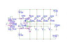
I can enter data into the simulator, so that they are not mistakes. Here you can see the correct function of restrictions.
An externally hosted image should be here but it was not working when we last tested it.
- Status
- Not open for further replies.
- Home
- Amplifiers
- Solid State
- Topology Federmann, HQQF-55 ...