Could also show a simulation with only gate voltage of both IRFP240 and IRFP9240 and output voltage of the amplifier, thank you!
Only peoples, who used them without real background.Simulators do not make mistakes
Last edited:
We are not curious about your simulations, but about practical results...do not say, that you have not time to try it...something different discourage to you try it, probably you do not like firework... 😱
Add emitorových resistance 0.22Ω. I see that the effect of temperature on the reduction of current is smaller!
Emitter resistors suppress thermal effects RDS and highlight temperature effects VGS!
Emitter resistors suppress thermal effects RDS and highlight temperature effects VGS!
An externally hosted image should be here but it was not working when we last tested it.
Michael,
you are apparently filled with a genuine sense of profound excitement for an underdeveloped idea, based on circulating marginated stereotype templates of random concepts, exacerbated by poorly substantiated technical suppositions and a neglectful, fragmentary cross-functional sequence analysis, lacking applicative-type structure norms and a reliable symptomatic long-term specificity, obscuring the outcome. You should, however, show your overwhelming but unfounded admiration in a calm and collected manner in oder to avoid finding yourself in the cumbersome situation of being threatened with a stiff bin time sentence.
Nice and decent post, perfect sense of humour. Thank you, Lumba. It could not be said better.
Cheers,
Pavel
Add emitorových resistance 0.6Ω. Switched zener diodes. Emitter resistors suppress thermal effects RDS and highlight temperature effects VGS!
Negative branch has no temperature dependence. Positive branch at a higher temperature, more current flows! Now there is an explosion!
Negative branch has no temperature dependence. Positive branch at a higher temperature, more current flows! Now there is an explosion!
An externally hosted image should be here but it was not working when we last tested it.
Last edited:
I give up this thread.
I can increase the emitter resistors to explode the negative branch.
I can generalize:
1) RE = 0Ω, the biggest positive influence of the temperature dependence RDS.
2) RE ≥ RDS, the suppression of the positive temperature dependence of the RDS and highlight the negative temperature dependence of VGS.
3) RE> RDS, negative temperature dependence VGS = unstable condition! Stability must be addressed else means.
Last edited:
Add emitorových resistance 0.22Ω.
3) RE> RDS, převládnutí negative temperature dependence VGS = unstable condition! Stability must be addressed else means.
Check your translator from Czech to English, you are mixing Czech and English language together.
I can increase the emitter resistors to explode the negative branch.
I can generalize:
1) RE = 0Ω, the biggest positive influence of the temperature dependence RDS.
2) RE ≥ RDS, the suppression of the positive temperature dependence of the RDS and highlight the negative temperature dependence of VGS.
3) RE> RDS, převládnutí negative temperature dependence VGS = unstable condition! Stability must be addressed else means.
Federmann,
let me tell you, the RDSon tempco effect is only valid when you are saturating the MOSFET, then you have Negative tempco, this works ONLY for Class-D / Switch Mode Power Supplies!
In the linear mode the RDSon has NO EFFECT on the tempco stability!
Cheers Michael
Again heaps of empty schemas !
It's a bad simulation.
Voltage UGS is derived from the current VAS and it decreases with temperature.
In the simulator will be no explosion.
It's a bad simulation.
Voltage UGS is derived from the current VAS and it decreases with temperature.
In the simulator will be no explosion.
Federmann,
let me tell you, the RDSon tempco effect is only valid when you are saturating the MOSFET, then you have Negative tempco, this works ONLY for Class-D / Switch Mode Power Supplies!
In the linear mode the RDSon has NO EFFECT on the tempco stability!
Cheers Michael
You're right, but compensate for this dependency transistor T109. The SPICE simulation is used to indicate only the dependence of terminal transistors.
Federmann,
The point is that you refuse to answer the serious questions:
HAVE YOU BUILT, TESTED, AND LISTENED TO THIS AMPLIFIER?
You have been asked this question by Chris (Anatech) and others many times! You have NOT yet answered. Therefore is no surprise that most readers are growing tired of your claims when you refuse to produce proper evidence (other than simulations) to support your claims.
When you ignore such questions you are going to be suspected of all of the charges which have been made against you. It is clear from the criticism of your design that well experienced designers and others have serious doubts regarding the safety of this circuit. Only by publishing screen pictures of your test results and by showing the amplifier in a full working condition can you even begin to save your situation.
I repeated several times, what is the current situation, which I can publish.
I have plenty of measured transistors. I'm putting together individual modules.
Modules for various performances, impedance and voltage. Only then will set their parameters, then I can write more.
PMA is certainly right, but the simulations SPICE_kompatibile usually very not different.
Preparation for construction.
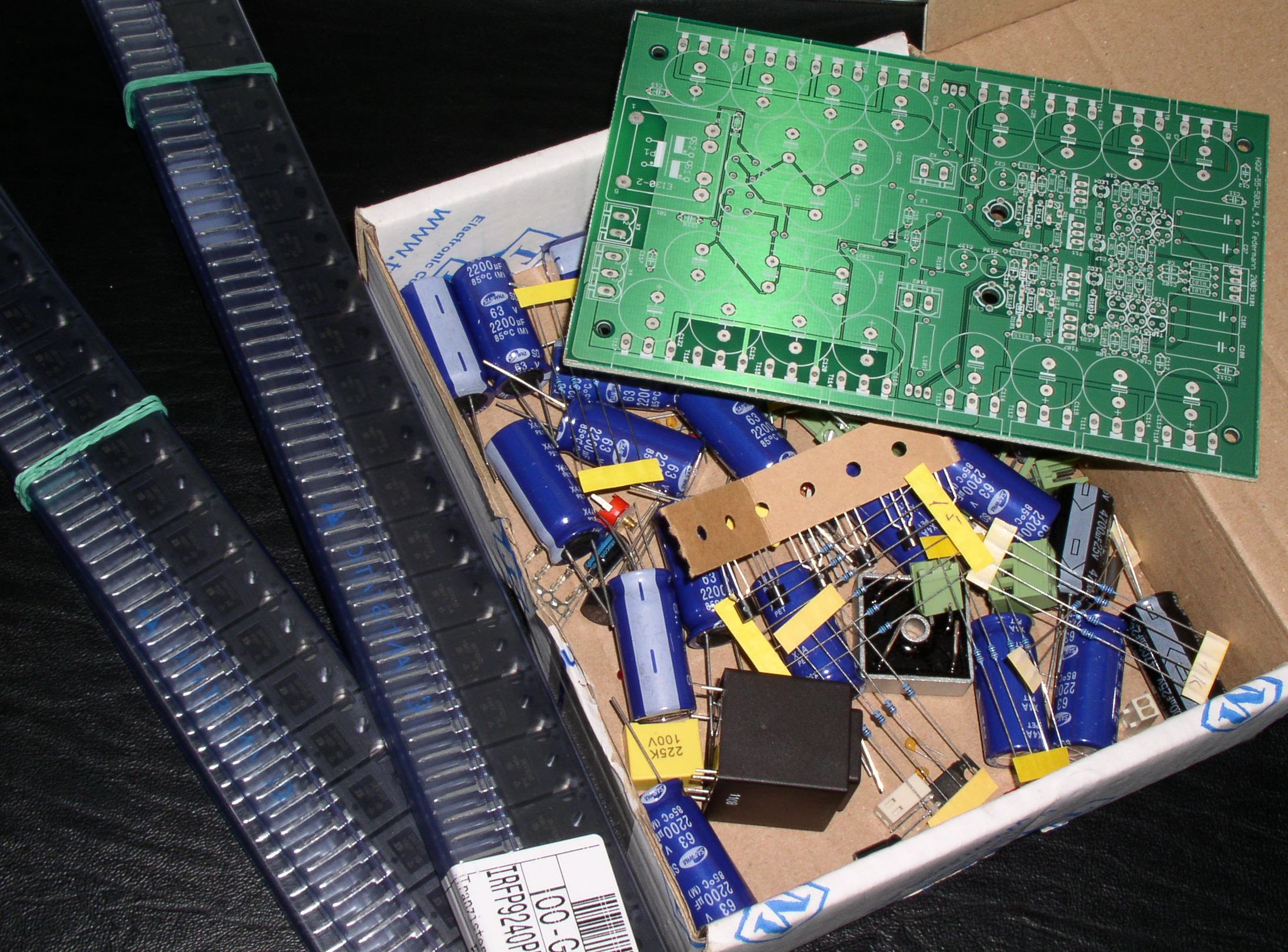
Current form, the assessment and fitting end transistors. He will be measured.
An externally hosted image should be here but it was not working when we last tested it.
I have plenty of measured transistors. I'm putting together individual modules.
Modules for various performances, impedance and voltage. Only then will set their parameters, then I can write more.
................................................................................ Only then will set their parameters, then I can write more.
Thank you - many are waiting with interest.
I, do not use any resistance, the essence of concentrations of power transistors I described here
An externally hosted image should be here but it was not working when we last tested it.
1) For each module must be selected same IRFP240 and appropriate Zener diode.
2) For each module must be selected same IRFP9240 and appropriate Zener diode.
3) Then optimally set 2SC3503, and adjusted its emitter resistor 15R.
Results will be published after a particular measurement. Set and measure 5 modules.
I'm sorry that I can not tell more.
I suspect the time you are spending posting all these simulations and arguing with your detractors would be FAR better spent actually building the amps and LISTENING to them in comparison with some accepted reference amp or amps.
And then getting the amp listened to by others with top top systems. When they lay $$ down for a copy - you KNOW it works well.
Regards, Allen
And then getting the amp listened to by others with top top systems. When they lay $$ down for a copy - you KNOW it works well.
Regards, Allen
Only you are talking about quiescent, 200A is result of your overcurrent "protection" at shorted output. You can use it as welding machine🙂).But only for one point....I'd never used quiescent current of 200A!
- Status
- Not open for further replies.
- Home
- Amplifiers
- Solid State
- Topology Federmann, HQQF-55 ...