Overcurrent "protection" is one mistake, showed frequency compensation second.. It will be for sure power oscilator (for short time before explosion), slow output stage and "fast" input and VAS without local compensation closed in global NFB..Unrealistic. We have to wait for measured results.
Yes, BV, we are still talking about the worst mistakes. Also, absence of the MOSFET driver circuit is a big issue.
thank you Federman for posting the picture and telling us about the current status of your project.
Regards
Regards
Stinius,
OT:
ouuh, but they certainly don't like campfires indoors!
Back to topic...I don't care very much about simulated circuits and virtual projects. If Federmann presents something readily build, I would be curious about it and would happily add my two cents why it works or fails.
Regards
OT:
ouuh, but they certainly don't like campfires indoors!
Back to topic...I don't care very much about simulated circuits and virtual projects. If Federmann presents something readily build, I would be curious about it and would happily add my two cents why it works or fails.
Regards
Last edited:
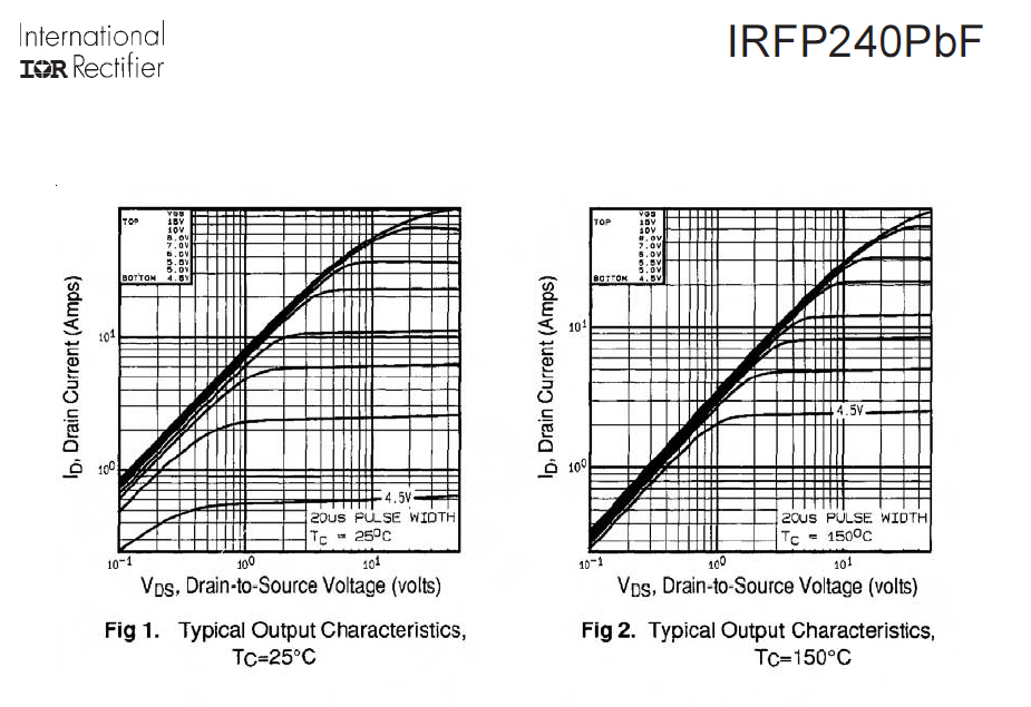
Here is why it will not work well without source resistors. Let's look at Vgs = 4.5V and Vds > 10V. In that case, the drain current is:
For temperature = 25 Celsius, it is Ids = 0.6A.
For temperature = 150 Celsius, it is Ids = 25A.
That is not a reduction in current with increased temperature!
All the parallelled transistors have the same Vgs so the hottest one will work harder than the others. Drawing a load line and pointing at it is nonsense. It is current sharing that is the problem, nothing to do with the load line.
However, the BUZ9** transistors you mention on your page do not have this problem. They can be parallelled just fine without resistors.
Transistors are next to each other, it is not possible that the first had a temperature of 25°C and the second 150°C. Forget the positive temperature coefficient RDS. I do not recommend temperatures above 80°C. Chips are selected for BUZ what the problem is to choose four transistors? Why look for problems where not?
Nice night
Juergen,
simulation, if properly used, is a great help and saves lot of time to a designer. However, its is the aid, not the final goal. Every professional company use simulators, please read Scott Wurcer's comment on that. But, if let in hands of pure theorists with no practical background, simulation may be misleading. Also, it does not substitute lack of professional background.
So please be careful before you disapprove simulation, rather consider the content.
Last edited:
Transistors are next to each other, it is not possible that the first had a temperature of 25°C and the second 150°C. Forget the positive temperature coefficient RDS. I do not recommend temperatures above 80°C. Chips are selected for BUZ what the problem is to choose four transistors? Why look for problems where not?
Nice night
No two IRF240 or IRF9240 have same charecteristics!!!!!
You consider one datasheet plot example as to be same for all devices, and this is a huge lack of understanding. The difference of characteristics leads to different current load to paralleled devices and therefore to different chip temperature. These things happen instantly and you do not see them in plots you are permanently displaying. Why do not you study publications on breakdown that danhard has linked here??
No two IRF240 or IRF9240 have same charecteristics!!!!!
Once again, good night

Federmann, please take a soldering iron in your hand, and build a working sample. Then you can defend your circuit ideas.
I am wailing, Federmann....try to make simply experiment: setup Vgs at 100mA Ids with IRFP240 and let it be. After a few seconds current will rise up to ampere region and after while device will be in silicon heaven...Now do the same with 2SK134 ( lateral type ) - here is Ids quite stable, or little fall with rising of temperature....It is reason, for what we can connect lateral ones in parallel, because they have in this working point zero Tc, but vertical ones not....Is not easy to understand ?
Hi Federmann,
I have a lot of actual experience with paralleled mosfets with no source resistors. Believe me, this doesn't work at +/- 50 VDC and it works much less well at +/- 70 VDC. If you do not perform exhaustive matching (two days and over 40 devices of each type for me), the amplifier will fail spectacularly! Any damping resistors will flame, as will most of the drive section.
High impedance gate drive doesn't work very well either. High distortion results.
This is why I am concerned with the design here. Did you say you actually have one working now?
-Chris
Transistors are next to each other, it is not possible that the first had a temperature of 25°C and the second 150°C.
It does not matter. Actually there was a typo in the last post. Currents should be 0.5A and 2.5A (not 25A). So how much positive feedback is there then? Have you calculated it? Current increases by 0.016A for every celsius increase in temperature, except for very low currents.
This means any mismatch in current will be amplified by about 1.8. This will in turn be amplified by 1.8 and so on... (0.016A/deg * 90V * 1.2deg/W) = 1.8. Assumed was 90V rails and Rth(j-s) = 1.2degC/W, 0.4 degC/W from the insulating pad.
1 + 1.8 + 1.8^2 + 1.8^3 + ... (infinite geometric series) does not converge. Any mismatch will be amplified by infinity.
At lower rail voltages it might share correctly if device matching is very tight. Somewhere around 30-40V might be OK.
anatech: What amplifier are you referring to that did not employ source resistors? The matching you speak of sounds like a major PITA...
Last edited:
Hi megajocke,
-Chris
Don't count on it! The level of matching is much closer than you want to know about. Bias will change very slowly and never really settle down. So just setting it up will be a problem. I've worked on both 2 and 4 pair type outputs. Not fun.At lower rail voltages it might share correctly if device matching is very tight.
-Chris

Don't worry anatech: I would never ever even think about designing something that way considering the large spread in mosfet parameters.  The matching nightmare would probably make me insane. 🙂
In an active load for PSU testing I made with mosfets each one got its own current regulator loop with an op-amp. 🙂
The matching nightmare would probably make me insane. 🙂In an active load for PSU testing I made with mosfets each one got its own current regulator loop with an op-amp. 🙂
Last edited:
Michael,
you are apparently filled with a genuine sense of profound excitement for an underdeveloped idea, based on circulating marginated stereotype templates of random concepts, exacerbated by poorly substantiated technical suppositions and a neglectful, fragmentary cross-functional sequence analysis, lacking applicative-type structure norms and a reliable symptomatic long-term specificity, obscuring the outcome. You should, however, show your overwhelming but unfounded admiration in a calm and collected manner in oder to avoid finding yourself in the cumbersome situation of being threatened with a stiff bin time sentence.
you are apparently filled with a genuine sense of profound excitement for an underdeveloped idea, based on circulating marginated stereotype templates of random concepts, exacerbated by poorly substantiated technical suppositions and a neglectful, fragmentary cross-functional sequence analysis, lacking applicative-type structure norms and a reliable symptomatic long-term specificity, obscuring the outcome. You should, however, show your overwhelming but unfounded admiration in a calm and collected manner in oder to avoid finding yourself in the cumbersome situation of being threatened with a stiff bin time sentence.
Hi megajocke,
I figured you knew, my comment was actually for people who have not tried to dance with this particular devil.
Hi Lumba,
You crack me right up!! 😀
Nicely put sir!
-Chris
Exactly! 😀I would never ever even think about designing something that way considering the large spread in mosfet parameters. The matching nightmare would probably make me insane.
I figured you knew, my comment was actually for people who have not tried to dance with this particular devil.
Hi Lumba,
You crack me right up!! 😀
Nicely put sir!
-Chris
Michael,
you are apparently filled with a genuine sense of profound excitement for an underdeveloped idea, based on circulating marginated stereotype templates of random concepts, exacerbated by poorly substantiated technical suppositions and a neglectful, fragmentary cross-functional sequence analysis, lacking applicative-type structure norms and a reliable symptomatic long-term specificity, obscuring the outcome. You should, however, show your overwhelming but unfounded admiration in a calm and collected manner in oder to avoid finding yourself in the cumbersome situation of being threatened with a stiff bin time sentence.
The pop on a stick has spoken! 🙄
Attachments

Simulators do not make mistakes, just people awarded incorrect data.Thank you Federmann for your latest simulation presented!
Could also show a simulation with only gate voltage of both IRFP240 and IRFP9240 and output voltage of the amplifier, thank you!
Then another haunted explosions.
I will return back to their topology. Voltage ±32V and load 6Ω.
An externally hosted image should be here but it was not working when we last tested it.
An externally hosted image should be here but it was not working when we last tested it.
An externally hosted image should be here but it was not working when we last tested it.
Voltage ±32V, load 3Ω, at 20°C.
An externally hosted image should be here but it was not working when we last tested it.
Voltage ±32V, load 3Ω, at 80°C.
An externally hosted image should be here but it was not working when we last tested it.
Voltage ±32V, load 3Ω, at 20°C ÷ 80°C. I see that increasing temperature and decreasing current!
An externally hosted image should be here but it was not working when we last tested it.
More shows temperature dependence of the RDS. Less temperature dependence is reflected VGS
Nice day
Last edited:
- Status
- Not open for further replies.
- Home
- Amplifiers
- Solid State
- Topology Federmann, HQQF-55 ...