FET intrinsic diode, aka. "body diode"
😎
I took intrinsic to mean part of the FET structure (like in a JFET (drain or source to gate)), not added on. Your not actually blowing the fet but the diode.
😎
Attachments
Last edited:
Chris
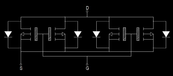
If you look at the schematics in post #1 you will see both N and P devices.
I think he explained somewhere that it was the program he used that did the mistake.
Anyway I’m concerned about the lack of a lot of resistors in the OP stage, so if Federmann could contribute about that it would be nice.
How is the weather in Canada? Here in Norway it’s soon winter.
Cheers
Stinius
It's true, Federmann changed the drawing in post #1, magnify his picture and we can see the schematics is done on 3rd of November while the post/thread started on 29th of September. PMA has the initial drawing that dates back in early September: http://www.diyaudio.com/forums/solid-state/154104-topology-federmann-hqqf-55-a-2.html#post1966770
We had snow here in Finland for some days ago but it's gone for now, colder than normally for the season and also my friends in Beijing reported snow already, hopefully we will get a white Christmas this year!


Cheers Michael
Attachments

Last edited:
Hi Michael,
In that case, stay warm!
If it's too cold to go out, design and build something! 🙂
-Chris
In that case, stay warm!
If it's too cold to go out, design and build something! 🙂
-Chris
It's true, Federmann changed the drawing in post #1, magnify his picture and we can see the schematics is done on 3rd of November while the post/thread started on 29th of September. PMA has the initial drawing that dates back in early September: http://www.diyaudio.com/forums/solid-state/154104-topology-federmann-hqqf-55-a-2.html#post1966770
I changed the scheme to be correct, that some confused. There is an old scheme in MC.
An externally hosted image should be here but it was not working when we last tested it.
Regardless your usual manipulation with drawings, which is not so important now, please answer the technical questions :
1. Have you already tested that your output stage with paralelled Mosfets, the circuit that does not use individual gate stoppers and that does not use individual source resistors would work, and would give the declared 2 x 500W?
2. You say you care about linearity of your input stage. Have you made any distortion simulations supporting your statement? We have already seen a sort of Bode plots.
I had build many types mosfet amps, with lateral and vertical types...I can to predict results...but maybe my way was not fifty ears correct...🙂
Regardless your usual manipulation with drawings, which is not so important now, please answer the technical questions :
1. Have you already tested that your output stage with paralelled Mosfets, the circuit that does not use individual gate stoppers and that does not use individual source resistors would work, ….
I long ago wrote that it is the same as BUZ906X4S, also has no emitter resistors and it works.
The Magnatec part shares same package and transistors are certainly made from the same piece of silicon. Do you expect the IRFP240 and IRFP9240 to have the same level of matching? Have you tried to operate them without source resistors?
I have a stock of some 150 + 150 2SK413/2SJ118 Hitachi MOSFET devices. It is impossible to find just pair of completely matched devices of the same type (let's speak only about 2SK413 for example). The IRFP device would be the same. Omitting source resistors means very different power load to individual transistors. This would result both in poor reliability and poor linearity.
I did many years in manufacturing semiconductors. I developed measuring methods and testers, to which measured the hundreds of millions of semiconductors. I know very well how to measure and select transistors.…This would result both in poor reliability and poor linearity.
Let it be, Pavel...F. probably did not know, that BUZ 906 is lateral type, which have much lower forward transconductance, much narrower tolerance gate threshold voltage and positive Tc..... mosfets are muchness, no problem for him....
Well said, syn08. I can even digest your attitude to us, though we have no commercial issues with Federmann, just technical. At least you seem to me to be an honest man.
 OK guys, get back on topic and stop the offensive language or there will be bin time.
I have a stock of some 150 + 150 2SK413/2SJ118 Hitachi MOSFET devices.
Pavel,
i knew there was something wrong with you.
Well said, syn08. I can even digest your attitude to us, though we have no commercial issues with Federmann, just technical. At least you seem to me to be an honest man.
PMA
It seems like syn08’s post is deleted, but I read it and I fully agree with what he was writing.
BTW it’s good to see that you think syn08 is an honest man.
Cheers
stinius
In case it is a lateral, it has also MUCH higher Rdson, and serial resistors are not necessarily needed.
In case it is a lateral, it has also MUCH higher Rdson, and serial resistors are not necessarily needed.
That's a secondary reason, if at all. The main reason is that laterals, also like JFETs, do not hog current. If one is drawing significantly more current than the counterparts, it gets hot, transconductance goes down, and the currents are, more or less, self balancing. This will preclude any physical damages, but is still not recommended for optimum performance.
BTW, I don't give a FF about posts being deleted. What's really worrysome is moderators allowing designs that may potentially damage property and health. Perhaps some moderators never had a chance to watch an overheating and blowing +/-80V 500W amp, it's never to late, just build this one and watch the fireworks, from a safe distance.
Totally agreed. All of us (you, Upupa, stinius, me and others) know what is a multiple pair IRF240/9240 without source resistors like. It would explode, as you have said, especially if amplifier is said to be 2 x 500W rated.
- Status
- Not open for further replies.
- Home
- Amplifiers
- Solid State
- Topology Federmann, HQQF-55 ...