Hi Federmann,
Have you constructed this yet? I agree with Ultima Thule in that the circuit can't work as drawn. Some English explanations would really help as well.
Hi cbdb,
Most signal J-Fets can have their D and S leads interchanged and the device will still work. Some types are dissimilar and will not work as well, but they will still work. This wouldn't be true is there was an intrinsic diode. Dual J-Fet chips are reverse P-N junction isolated (that forms an SCR) that may cause trouble if the right voltages occur between the substrate and other leads. May be you are thinking of this?
-Chris
Chris
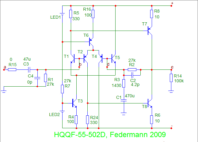
If you look at the schematics in post #1 you will see both N and P devices.
I think he explained somewhere that it was the program he used that did the mistake.
Anyway I’m concerned about the lack of a lot of resistors in the OP stage, so if Federmann could contribute about that it would be nice.
How is the weather in Canada? Here in Norway it’s soon winter.
Cheers
Stinius
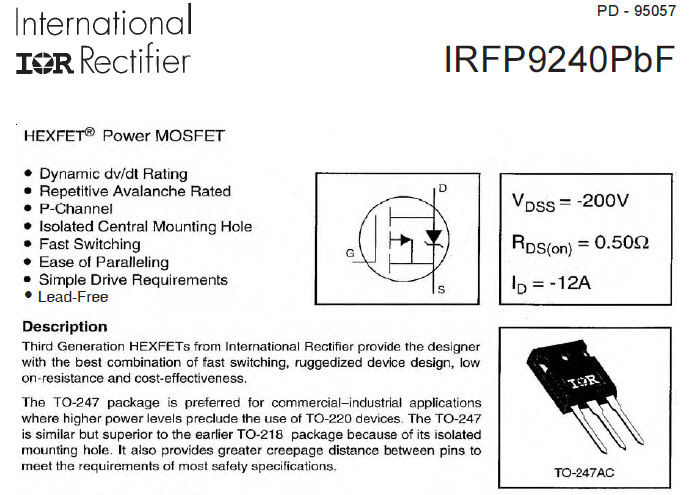
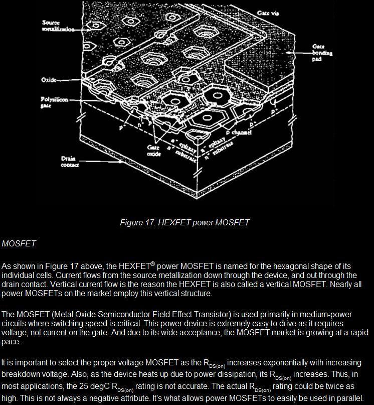
Power MOSFET is made up of many cells (transistors), 100tisíc and more. As the power MOSFET is heated by power dissipation, its RDS (on) increases. It is important to select the correct voltage MOSFET. I know that no one applied, but I do.
Have a nice day.
I am the first who is looking distortion in the amplifier input transistors. When the slow amplifier and input transistors work in the short term nonlinear region.
Wrong.
I took intrinsic to mean part of the FET structure (like in a JFET (drain or source to gate)), not added on. Your not actually blowing the fet but the diode.
Federmann -
Though we do not see much of your amplifier yet, you have placed on your webpage a lot of Pavel Dudek's circuits - with your comments. I believe you have Pavel's permission to display his circuits.
Zesilova�e a fakta o jejich konstruktérech
Though we do not see much of your amplifier yet, you have placed on your webpage a lot of Pavel Dudek's circuits - with your comments. I believe you have Pavel's permission to display his circuits.
Zesilova�e a fakta o jejich konstruktérech
I am the first who is looking distortion in the amplifier input transistors. When the slow amplifier and input transistors work in the short term nonlinear region.
Not sure what that means. Woudnt emiter resistors on the diff pairs reduce their distortion?
Is not a supporter of THD measurement range, in my opinion is not sufficiently informative about the properties of amplifiers. I we will wait until everything is ready and will be measuring and listening tests.
Yes, indeed you're right, but the gain on the diff pairs fall and the problem is downstream.
The issue is very complex. In preparing the subject article, which will explain everything. Will be a lot of pictures that help to understand everything.
So you sacrifice the diff pair linearity to use the gain to decrease distortion in other stages with global feedback? I didnt think one had to lose that much gain to get good improvements with a diff pair.
Each transistor in a row, turning phase, I want a very small phase angle. Each transistor further increases the claims. That is why I use only two transistors in a row.
Hi Stinius,
Right you are! Thank you for directing my attention there. Now I know it should work. 🙂
I have the same concerns over a lack of source resistors. I did warranty work for a company that didn't use them either. Not a successful way to produce a product, and the output matching was too tight for production. I needed 40 parts to select 4 that were close enough. That's per polarity!
It is beginning to cool as we approach snow season (evil white s*). We sometimes have snow by this time, and some years our Christmas is still green. You just never know these days. 40 years ago, we were frozen and covered by snow by now. We just had a bit of hail this afternoon. 😡
Hi cbdb,
Read Doug Self's book. He goes through this in detail. It's an accepted way to reduce distortion while linearizing the input stage. By increasing the tail current, you can regain the lost transconductance.
Also, in the symasym thread, the same procedure was discussed as an option. There's a lot of really good stuff in those threads.
Hi Federmann,
-Chris
Right you are! Thank you for directing my attention there. Now I know it should work. 🙂
I have the same concerns over a lack of source resistors. I did warranty work for a company that didn't use them either. Not a successful way to produce a product, and the output matching was too tight for production. I needed 40 parts to select 4 that were close enough. That's per polarity!
It is beginning to cool as we approach snow season (evil white s*). We sometimes have snow by this time, and some years our Christmas is still green. You just never know these days. 40 years ago, we were frozen and covered by snow by now. We just had a bit of hail this afternoon. 😡
Hi cbdb,
Read Doug Self's book. He goes through this in detail. It's an accepted way to reduce distortion while linearizing the input stage. By increasing the tail current, you can regain the lost transconductance.
Also, in the symasym thread, the same procedure was discussed as an option. There's a lot of really good stuff in those threads.
Hi Federmann,
That is a little unfair as a comment. Others who have gone before have done a great deal of work on this. I can accept that you are making this a design focus, to optimize linearity in the input stage, and to speed up the amplifier down the line as well.I am the first who is looking distortion in the amplifier input transistors. When the slow amplifier and input transistors work in the short term nonlinear region.
-Chris
Last edited:
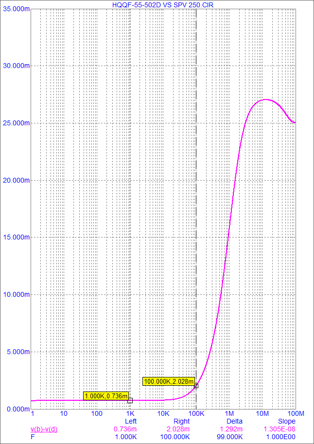
I have a scale bias, the margin of profit for 100kHz. Reserve in profit shows the phase and vice versa.
These are the main features of "Topology Federmann, HQQF-55 ..."
On my site I have nothing to come diyAudio.
Have a nice evening
These are the main features of "Topology Federmann, HQQF-55 ..."
Of course, I had a lot of designs, which I refer in their work.That is a little unfair as a comment. Others who have gone before have done a great deal of work on this. I can accept that you are making this a design focus, to optimize linearity in the input stage, and to speed up the amplifier down the line as well.
This is a concern for the moderators of diyaudio. Let's just say we strongly discourage the use of another person's IP without their permission. It's certainly not allowed here, and we do not allow links to such a place.
On my site I have nothing to come diyAudio.
Have a nice evening
Hi cbdb,
Read Doug Self's book. He goes through this in detail. It's an accepted way to reduce distortion while linearizing the input stage. By increasing the tail current, you can regain the lost transconductance.
Thanks but I new this in 82, from "Analysis and Design of Analog Integrated Circuits" Gray and Meyer (1977).
What I wanted to know was Federmanns reason, which he just explained: If I understand correctly more gain at input = less stages = less phase shift. Dont know if I totally agree. I see it like this: "the linear range of operation is extende by an amount approximately equal to IeexRe. The voltage gain is reduced by approximatley the same factor" . In a feedback amp if you decrease the open loop gain, you increase the diff input voltage, so the gain and the linearity of the input diff pair become more complicated in a feedback loop. I have read Selfs book but dont remember him mentioning this(maybe I missed it. (And increasing the gm by increasing Iee is fairly limited by the transistor beta/Ic linearity)
So let's summarize what we have had till now.
- a simulation of an amplifier, not a working sample or prototype
- this simulation with paralelled MOSFET output devices does not use individual gate stoppers and does not use source resistors. We are persuaded by the author that it is OK
- the input stage is said to have low distortion, though no distortion simulation has been shown.
Regarding base stoppers and source resistors, I say that only a working sample of this 2 x 500W amplifier can convince me that it is OK.
- Status
- Not open for further replies.
- Home
- Amplifiers
- Solid State
- Topology Federmann, HQQF-55 ...