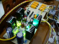
I have just tested the assembly ( basic version) after goofing LED connections and missing one jumper. Everything looks allright except relay power.
- There is an oscillation across Relay power - around 5 -6 Khz - causes Whooshing continuous sound. IF you check voltage across the diode/could see 5 khz oscillation ? The sound starts when start delay finishes and power is applied to the Relay? I have to check few things later today when I come back in the night to work on this. I also see voltage being 10.5 V and -11.1V not symmetrical due to LED mismatch probably. I will do further testing later. I will try to load the picture soon
kannan
Yes, after the capacitor gets up to 6-8V, the npns open and latch the relay. Then you can have sound. What bjts you used there? You can see the relay voltage on the oscope between the 600R//600R and ground. Oscillation there? Mysterious.
I have just tested the assembly ( basic version) after goofing LED connections and missing one jumper. Everything looks allright except relay power.
- There is an oscillation across Relay power - around 5 -6 Khz - causes Whooshing continuous sound. IF you check voltage across the diode/could see 5 khz oscillation ? The sound starts when start delay finishes and power is applied to the Relay? I have to check few things later today when I come back in the night to work on this. I also see voltage being 10.5 V and -11.1V not symmetrical due to LED mismatch probably. I will do further testing later. I will try to load the picture soon
kannan
Is the wooshing sound something you hear without hooking it up I assume to listen? Sounds like the issue I face.
These are not offsets, its your regs symmetry. Has to do with Vbe. Measure your DC offset at the output. If under 5mV, leave it as it is. Depending on the B1 jfet match, some reg assymetry is beneficial, as it offsets the offset.😀
If the output DC is more than 5mV, you can give more voltage by substituting stronger Vf led(s) in the opposite supply. I.e. If your offset is +5mV you want to make the negative reg Vout stronger. If over -5mV, do the opposite. I could get it down to absolute zero that way. But guess what, it amounts to absolutely nothing. Not safer, no better square wave, or any better sound. If you got DC audio out offset in the +/-5mV range, just drink a beer. Forget it.
The DC offset at output measures .2-3mv
Is the wooshing sound something you hear without hooking it up I assume to listen? Sounds like the issue I face.
Try another type of low Hfe NPN transistors in the delay circuit? Like BC182,3,4. But first it has to be seen with oscope. If its there, stick a 0.1uF between 7812 out and ground pins directly on them underneath the board, first.
I found the relay driving NPN ( BC550B) is having Oscillation. I connected a ceramic .1uF across its base to earth . This reduced this to a minimal level and the sound is gone. The sound is coming from relay chatter due to low frequency oscillation. still I see a small oscillation on my Fluke 867( I do not have a scope but my Fluke 867 shows oscillations as it is almost a mini scope). I may have to try a different NPN here or a suitable cap across the supply line. I am going out now and will be back after 8 hours to do further testing. Offset is almost nil on the buffer side. The Regulation seems fine and it looks working fine except this small oscillation and it is near the Buffer amplifier /so should be eliminated completely
kannan
kannan
Probably some trace inductance or the TQ type coil excites the 550s. But there is no reason to be 550s. They can be much slower. We check a couple of suitable ones and update the BOM. Or stick a ceramic underneath. Try between collector and base also. Crt did not use TQ relays and did not chance on such an issue. Neither did I. Leave your reg assymetry as it is, it worked fine with your JFET matching in your audio side. Still we have to see if that warmer than others mosfet has a different enough vgs or its 3 leds are a bit strong. We will know when you tell me the R1 vdrops. Good for now.
There is one thing about crt's circuit and build that has me puzzled: he is just testing so he doesn't have a potentiometer in the circuit, but it also looks as if there is just a wire bridge in each channel instead.
So, what's the input impedance of that circuit variant? I almost certainly missed something in his pictures, but I've looked at them a couple of times and can't figure it out.
sorry, i forget to tell if i use PC for source so i don't need volume control.🙂
i put 22k to replace 220K.
but after i read this, i try to put pot. (alps motor) 50K and change the 22K with 47K.
everything is fine, NO PROBLEMO!

Attachments
Is there a price on the board yet?
They are nice,the boards..
No price on the boards yet. We need to weed out any potential changes to the boards with the proto boards, before I order more. In a bit I will start a shared google spreadsheet, and people can add their interest in ordering to that.🙂
Nice to see your boards populated, great job !
Let me know what values/parts are to be modified in the BOM.
I will post the revisited version.
Let me know what values/parts are to be modified in the BOM.
I will post the revisited version.
Let them see what npn's don't react with the TQs first, or what comp cap they will end up with and where first. Also let em run the protos enough so to check if they will find some small sink for the 7812 advisable, or if the mosfets are better under board on an aluminum plate, how does it sound with what pots, etc. Just my 2c.
You're absolutely right Salas.
I've gathered most of the parts too.
I'm involved and my care is to deliver a trusted/validated BOM for all of us.
😎
I've gathered most of the parts too.
I'm involved and my care is to deliver a trusted/validated BOM for all of us.
😎
Main thing is that it presented no dead end issues and its functional with low offset straight away. Running protos was the decent thing to do. You see, how could we know that the 550 does not like the TQ coil, when Ferds and Crt's working ones never bothered? No mean feat to hit it with one shot for a pcb project collaborated via forum and email over Europe, Asia, and America. 
I'm involved and my care is to deliver a trusted/validated BOM for all of us.
😎
Of course. You can't beat communal work. Kudos to all the dedicated DIYers that resurrected it.

Ok I have a 550 to go in but now we think the TQ2s don't like this one. My spare parts pin is pretty low on NPNs other than 550s. I have some 3904 and 2222a, I don't know what to look for to tell me what a good NPN to put here would be. Thanks.
Oh and no resistors in my mailbox today😡😡
Oh and no resistors in my mailbox today😡😡
My mezmerize TQ2-12V relais work just fine with two BC550C transistors.
I'll check for any and all weirdness like oscillations etc., but there is currently no evidence of anything weird.
I'll check for any and all weirdness like oscillations etc., but there is currently no evidence of anything weird.
My mezmerize TQ2-12V relais work just fine with two BC550C transistors.
I'll check for any and all weirdness like oscillations etc., but there is currently no evidence of anything weird.
The 12V should have different coil inductance. So with 12V TQ-2s no problem is the 550Cs. Check for one proto.
Do you use just a jumper instead of the 600R//600R, or they are in circuit?
P.S. Have you started auditions?
Ok I have a 550 to go in but now we think the TQ2s don't like this one. My spare parts pin is pretty low on NPNs other than 550s. I have some 3904 and 2222a, I don't know what to look for to tell me what a good NPN to put here would be. Thanks.
Oh and no resistors in my mailbox today😡😡
Both interesting to check since they are low hfe. They have E,B,C as you face them, when 550 is C,B,E so you have to place them in opposite way for testing.
If it will not do, a ceramic between C,B should do the trick.
- Home
- Group Buys
- GB for DC coupled B1 buffer with shunt PSUs