Wow, Wow, Wow!
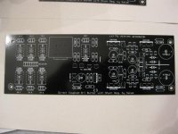
They look great! Love the B&W look. I think this will need a plexi cover to show it off, I'd better be neat and tidy!!
They look great! Love the B&W look. I think this will need a plexi cover to show it off, I'd better be neat and tidy!!
Wow, Wow, Wow!
They look great! Love the B&W look. I think this will need a plexi cover to show it off, I'd better be neat and tidy!!
nah, your beta-builder, you need to huck together quickly, make it messy!

A little Natalie MerchantEsque!
Have I been wrong? Have I been wise? Have I been strong? Have I been hypnotized, mesmerized. By what my eyes have found? In that great street carnival
Have I been wrong? Have I been wise? Have I been strong? Have I been hypnotized, mesmerized. By what my eyes have found? In that great street carnival
All the beta boards have been sent out.
Does anyone want to test one purely as a regulator for another project?
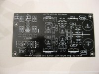
Just dont fill out the front of a hypnotize. The three large solder pads in the bottom and unmarked holes on top represent ground v+ and v-.
Does anyone want to test one purely as a regulator for another project?
Just dont fill out the front of a hypnotize. The three large solder pads in the bottom and unmarked holes on top represent ground v+ and v-.
about Led position
*Reloaded by Salas so it ain't black when blown up.
*Reloaded by Salas so it ain't black when blown up.
Attachments
Last edited:
about Led position
I think you forgot to turn the LEDs on - seems pitch black to me!
Assertive news
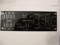
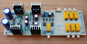
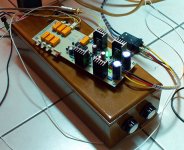
Seems like you test builders will be having a joyful task. Crt has beaten us for quickness, and he already tested a Mesmerize, built on the same circuit and layout with slight physical differantiations about using another 12V relay model that was available to him. He emailed me 2 pictures, and told me that both the time delay and input switching work flawlessly. He added little sinks also, just bcs he lives in a warm climate and he uses closed box. Not that they are neeeded at this consumption. He also listened to it VS his earlier non delayed or switched straight version build, and it was sounding the same to him. So the relay switches seem benign enough subjectively. He used some of the most successful DIY amps, like DX, AKSA, Symasym, to check it with, and got no noises for functions.
Seems like you test builders will be having a joyful task. Crt has beaten us for quickness, and he already tested a Mesmerize, built on the same circuit and layout with slight physical differantiations about using another 12V relay model that was available to him. He emailed me 2 pictures, and told me that both the time delay and input switching work flawlessly. He added little sinks also, just bcs he lives in a warm climate and he uses closed box. Not that they are neeeded at this consumption. He also listened to it VS his earlier non delayed or switched straight version build, and it was sounding the same to him. So the relay switches seem benign enough subjectively. He used some of the most successful DIY amps, like DX, AKSA, Symasym, to check it with, and got no noises for functions.
Attachments
All the beta boards have been sent out.
Does anyone want to test one purely as a regulator for another project?
Just dont fill out the front of a hypnotize. The three large solder pads in the bottom and unmarked holes on top represent ground v+ and v-.
I have the ICs on had to build the regulator section. I do not have a scope for measuring the results but I will use it as the supply for the my DAC (buffalo24) I/V stage and report listening impressions.
This DC B1 shunt's section is set for +/- 70mA and around +/-10V as it is. What are your consumption needs? If more in current or voltage you have to play with the Leds and R1 and gonna need sinks.
Thanks Salas, I do need to adjust the voltage to +/-15V. The current should be fine but I will double check. I plan on either using heatsinks or simply under mounting the fet to my chassis which is a 6mm aluminum plate.
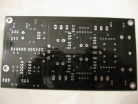
My board arrived today! It looks even better in person. I will get started right away but I am still waiting on the resistors! I guess that's what I get for getting them fancy bootique parts. I ordered them almost 2 weeks ago, hopefully they will be here tomorrow.
Thanks Salas, I do need to adjust the voltage to +/-15V. The current should be fine but I will double check. I plan on either using heatsinks or simply under mounting the fet to my chassis which is a 6mm aluminum plate.
That means you will need 4 Leds plus a resistor instead of the 5th led. You will start with a jumper instead of a 5th led. You will tell me the mV you measure across each 10R between the most left 100uF caps. Then I will determine a resistor per side that will provide the needed voltage drop so to reach a symmetrical +/-15V. It will be running constant current and bcs small its going to contribute maybe less than a led for noise. At such voltage you will surely need to bend the fets towards some sinking or use small individual sinks. I saw that B32s needs +68/-43mA at +/-15V for its analogue stage. You will make the double 68R per side, double 33R 1W. Mount them a bit proud off board on different levels by using more leg length, so air circulates between them and the board.That will give about +/- 150mA. Good headroom and keeps the Mosfet transcoductance alive enough. Your PTX must be 2X15AC, 50VA. I guess it has good chances to be likened on the B32s. You will do the review, after 48h break in.

Attachments
My board arrived today! It looks even better in person. I will get started right away but I am still waiting on the resistors! I guess that's what I get for getting them fancy bootique parts. I ordered them almost 2 weeks ago, hopefully they will be here tomorrow.
My Basic board arrived today - will probably ready for testing tomorrow
 !!!!
!!!!Nice PCB - looks great
kannan
Seems like you test builders will be having a joyful task. Crt has beaten us for quickness, and he already tested a Mesmerize, built on the same circuit and layout with slight physical differantiations about using another 12V relay model that was available to him. He emailed me 2 pictures, and told me that both the time delay and input switching work flawlessly. He added little sinks also, just bcs he lives in a warm climate and he uses closed box. Not that they are neeeded at this consumption. He also listened to it VS his earlier non delayed or switched straight version build, and it was sounding the same to him. So the relay switches seem benign enough subjectively. He used some of the most successful DIY amps, like DX, AKSA, Symasym, to check it with, and got no noises for functions.
I like the choice of the more easily available standard telecom relais with gold plated silver contacts ! I would have voted for those.
Salas, Thanks for the support. I have a 2x15ac 50va transformer already installed in the dac to power the current twisted pear power supply. I have been listening to this dac for a least 6 mos so I am very familiar with the sound.
I will PM teabag to see confirm that he will ship me the board.
Thanks again, Nick
I will PM teabag to see confirm that he will ship me the board.
Thanks again, Nick
- Home
- Group Buys
- GB for DC coupled B1 buffer with shunt PSUs