Sorry should have specified I have the 5v version. what 55o do you have c,b,a?
He wrote 550C.

Just a jumper, no resistors.
The 12V should have different coil inductance. So with 12V TQ-2s no problem is the 550s. Check.
Do you use just a jumper instead of the 600R//600R, or they are in circuit?
P.S. Have you started auditions?
Just a jumper, no resistors.
As specified then. Great. I have 12V relay too, no surprises. But we will determine some carefree npn or compensation for our 5V friends too, because 5V TQs appear on ebay and some have already bought very early. Also its good to have option against online vendor TQ versions stock. We will document the 5V option and its best npns or comp cap clearly in the BOM when the communal mind will conclude.

I am back home and will be sitting with this in an Hour or so. I will report further on this. The relay I used is Omron 12V as per BOM G6H type procured from Mouser. I find the voltage on the coil is only 9 V due to the resistors after 7812 Voltage regulator? I installed the resistors ( 600 Ohm?- 2numbers) as the board shows it.Do we need these as they drop the voltage to 9V ? I used matched Fets on Buffer and offset is almost nil - I do not even see 1mV. Also I may be bit finiky about Mosfet heating up - probably it is normal heat expressed so far, But I will check without HS also. I will get a chance to listen to this today. I am confident that rest of the functions - Shunt/buffer is working fine ( with voltage offset between +/- rails which is again -10.9 V and + 10.4 V.
So this relay cahtter can be cleared with some changes, I think we are good to go unless somebody else reports any issues
kannan
So this relay cahtter can be cleared with some changes, I think we are good to go unless somebody else reports any issues
kannan
Questions for you. 1. What is the voltage drop across the 68R//68R on your warmer Mosfet side? 2. Did you try the comp cap from C to B also?
The 12V Omron dont need the resistors. Just a jumper. Their coils have exactly the same resistance as the various TQ2s. I will not be surprized if the resistors for 5V are a factor for the chatter. Do the jumper first.
The 12V Omron dont need the resistors. Just a jumper. Their coils have exactly the same resistance as the various TQ2s. I will not be surprized if the resistors for 5V are a factor for the chatter. Do the jumper first.
Listening and some more checking of the mezmerize is on hold for me until sometime much later this evening. I need to invest in family harmony for the next couple of hours.
I got my boards today. Parts are in the mail, so I am on hold until all the pieces are in hand. Arrgh Shiver me timbers why aren't my parts here? Some scurvy dog must sittin on them in the post. Arrgh!! (today is international talk like a pirate day, so I thought that was necessary
Listening and some more checking of the mezmerize is on hold for me until sometime much later this evening. I need to invest in family harmony for the next couple of hours.
Family first. Let us know when able.
I got my boards today. Parts are in the mail, so I am on hold until all the pieces are in hand. Arrgh Shiver me timbers why aren't my parts here? Some scurvy dog must sittin on them in the post. Arrgh!! (today is international talk like a pirate day, so I thought that was necessary
😀
Questions for you. 1. What is the voltage drop across the 68R//68R on your warmer Mosfet side? 2. Did you try the comp cap from C to B also?
The 12V Omron dont need the resistors. Just a jumper. Their coils have exactly the same resistance as the various TQ2s. I will not be surprized if the resistors for 5V are a factor for the chatter. Do the jumper first.
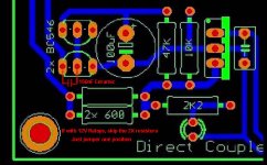
Finally - 12V with jumper at 600 Ohm resistor location also caused chatter- increases with the cap aross base to Earth ( more of short spikes from the Transistor collector) I soldered .15 UF Cap across base and collector of BC 550B , it stopped. I removed the other Ceramic 10NF cap. Now I see 3mV noise across supply to the coil. So solution is this Cap incase you hear Whoosh type of noise from the relay or provide this on the BOM. BOM should also specify jumper for 12V relay clearly.
Coming to the Mosfet heat - I was wrong - it is uniform on both the supply lines /no need for heat sinks and it is hot to touch as reported. The voltage across 68 R - 2.1 V on Negative leg and final voltage is -10.4V and 2.4V on positive leg with +10.9V output. Offset across Buffer is nil - I had used closed match Fets ( actuallY Spencer in this forum sells such FETs - worth buying from him - see thread on 2SK 170 sales)
Now I have to connect the RCA's etc for testing the sound from the buffer ! I will post my observations tomorrow ( it is night at East Coast )
I will also post more photos tomorrow
kannan
no more oscillations
I did the tweak, I tried a 100nf wima with no luck, but a .1uf (fairly large x2 cap) did the trick. It seems to affect the start on time click slightly.
I think we are on the right path.
This seems to be solving the problem.
I would rather fix it with different transistors,
I am using 2x 546c right here.
I dont have any others to try here yet.
Good work Kannan! Chatter occurence remedy is 150nF ceramic cap from relay driving BC550's base to collector underneath, direct to transistor with short legs. Check.
Is my attached guide OK?
I did the tweak, I tried a 100nf wima with no luck, but a .1uf (fairly large x2 cap) did the trick. It seems to affect the start on time click slightly.
I think we are on the right path.
This seems to be solving the problem.
I would rather fix it with different transistors,
I am using 2x 546c right here.
I dont have any others to try here yet.
Its worth to try some others. Its more of an elegant solution. Now why Grufti with BC550C's does not get it? Trial on error will show. And a little poll between the proto testers for npn substitutions. What exactly are your relays Tea-Bag?
P.S. The fun starts when the auditions begin.
P.S. The fun starts when the auditions begin.
Its worth to try some others. Its more of an elegant solution. Now why Grufti with BC550C's does not get it? Trial on error will show. And little poll between the proto testers for npn substitutions. What exactly are your relays Tea-Bag?
http://www.mouser.com/Search/ProductDetail.aspx?R=TQ2-5Vvirtualkey66710000virtualkey769-TQ2-5V
or mouser 769-tq2-5v
I thought they were the preffered one's...Not sure why I would not want to use 12v, as its close to the source voltage. But I dont want to de-solder these critters, no way!
They are good, as much as the 12V ones. Do they drop at 5V after the 300R//300R on the Mezmerize when 2 are on? (Delay & one input).
They are good, as much as the 12V ones. Do they drop at 5V after the 300R//300R on the Mezmerize when 2 are on? (Delay & one input).
from two 300r's to small ground jumper is 4.66volts.
 And when you gonna listen to it, give it some break in also? What kind of a system you gonna use?
I'll be hooking it up to either F5 (danger) or F3 on top end, to a DCX2496 for the bottom end, which is driven by F5 to OBs. Mostly listen to CD's through a modded DVD-2900. I am missing parts to give it box and a serious listen right now. Hopefully with some jumper wires, I can put it to work in the basement fairly soon. Progress will be slow now, child is sick.🙁 Football on tommorow.😀
I have 2.1mV (RMS) of AC on the 12V supply for the relays and absolutely no chatter. Dumb luck ... happy combination of parts ... good weather ... great soldering skill (unlikely) ... I for one have no clue why my relays are doing just fine.
It is always difficult to prove why something actually works. It is usually easier to figure out why it doesn't.
It is always difficult to prove why something actually works. It is usually easier to figure out why it doesn't.

- Home
- Group Buys
- GB for DC coupled B1 buffer with shunt PSUs