Oh yes, I have begun to play music.
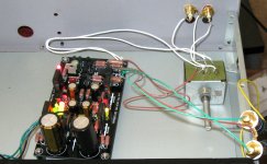
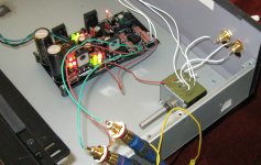
The Mezmerize has been on and playing music for about 12 hours now. I started to pay attention about two hours ago. Power amp is a PP EL34, speakers are open baffle.
The sound is extremely nuanced and still relaxed. "Hmmh, I didn't know he picked up a different guitar to play that piece", was one of the first reactions I had. Then I played Gidon Kremer - Homage à Piazzolla and thought that his violin sounded more alive than I had ever heard it. Lyrics are extremely easy to understand with music playing through the Mezmerize, musical lines weaving their way through a piece of music are more evident than I recall from listening to some familiar recordings.
It is always a good sign to me when I respond more to the music than to the "sound" of the equipment.
I am fairly used to listening with a "regular" B1 and I clearly prefer this DC coupled beauty.
Great work by a long list of contributors: the ancients ... Nelson ... and then all the others in the diyaudio threads on the B1 and its offspring.
Pictures tomorrow.
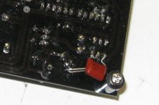
Good work Kannan! Chatter occurence remedy is 150nF ceramic cap from relay driving BC550's base to collector underneath, directly to transistor pads with short legs. Check.
Is my attached guide OK?
Correct but I used PP capacitor as I felt that the Oscillation is low frequency one and ceramic is for HF oscillations-
Is this caused probably by the relay's fast switching capabilities or transistor bandwidth coupled with trace/coil inductance interacting? I can check later using BC550C. very intersting sound - whistling sound!
I have uploaded photos.
I am playing music and it is pretty good but I may have to check it out over next week.
My main concern is about LED pads which gave way while trying to desolder/solder back - so I just joined the one LED lead directly to the next LED lead wherever the pad had issues.
Signal in and out pads are very close - if you are trying to solder thick wires like mine it is an issue - better to use lead wire like to join such wires ( photos for reference).
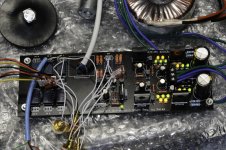
PCB black mask leaves very little pad area for visibility. And the black color of the solder mask covers it making it bit unclear about the quality of soldering. However I have not found any other issue making the assembly. We may have to make an assembly guide if possible showing the jumper postions and options along with schematics for people assembling. If there is no other complaints we can go ahead with the PCB as the relay fits /works perfectly/ all connections are perfect
I used MUR diodes /Nichicon Muse caps/Dale resistors for this build- connectors are Vampire
Attachments

Correct but I used PP capacitor as I felt that the
My main concern is about LED pads which gave way while trying to desolder/solder back - so I just joined the one LED lead directly to the next LED lead wherever the pad had issues.
Signal in and out pads are very close - if you are trying to solder thick wires like mine it is an issue - better to use lead wire like to join such wires ( photos for reference).
What size PP cap did you use?
I desoldered a few things on some larger pads without problem. I desoldered the resistor and a 20ga bus wire once or twice at about 900F.
I think part of the soldering - desoldering process is using good solder (I use cardas 60/40) and solder wick.
It looks like CRT got some connectors for the In/Out sections, I did not order such a thing but probably a good idea. I think a preamp generally could use 24 ga-28ga wire typically.
If the consensus (for proto builders) is to change color, or get larger solder pads for In/Outs we could ask CRT for another version. I think it looks fine.
I use a magnifying lamp with a light to check all solder connections. It helps a lot.
Last edited:
Oh yes, I have begun to play music.
The Mezmerize has been on and playing music for about 12 hours now. I started to pay attention about two hours ago. Power amp is a PP EL34, speakers are open baffle.
The sound is extremely nuanced and still relaxed. "Hmmh, I didn't know he picked up a different guitar to play that piece", was one of the first reactions I had. Then I played Gidon Kremer - Homage à Piazzolla and thought that his violin sounded more alive than I had ever heard it. Lyrics are extremely easy to understand with music playing through the Mezmerize, musical lines weaving their way through a piece of music are more evident than I recall from listening to some familiar recordings.
It is always a good sign to me when I respond more to the music than to the "sound" of the equipment.
I am fairly used to listening with a "regular" B1 and I clearly prefer this DC coupled beauty.
Great work by a long list of contributors: the ancients ... Nelson ... and then all the others in the diyaudio threads on the B1 and its offspring.
Pictures tomorrow.
Your description is spot on. Enjoy.
My main concern is about LED pads which gave way while trying to desolder/solder back - so I just joined the one LED lead directly to the next LED lead wherever the pad had issues.
Signal in and out pads are very close - if you are trying to solder thick wires like mine it is an issue - better to use lead wire like to join such wires ( photos for reference).
PCB black mask leaves very little pad area for visibility. And the black color of the solder mask covers it making it bit unclear about the quality of soldering. However I have not found any other issue making the assembly. We may have to make an assembly guide if possible showing the jumper postions and options along with schematics for people assembling. If there is no other complaints we can go ahead with the PCB as the relay fits /works perfectly/ all connections are perfect
I purchased the headers specifically for the I/O as it seemed to me the PCB was designed for them. Never used them before but I think I will like them, I looked them up and it seems the connections will be strong and of a high quality. I had no issues with the color of the PCB and soldering or QCing the soldering so far. But I am getting older and use a bright light and magnifier for working and a 10x loupe to check my work. Also had no issues with spacings or the size of anything, the layout seemed spacious and the pads generous. This could be because my last few projects were very small and compact with a lot of SMD like the Bantam and y1 DACs, not to mention the CTH headphone amp! Regarding the relay, I will try using a BC550C first and hopefully it will work as grufti's did, if not I will try a 2222a and then the cap.
I am hoping my package of resistors comes Monday so I can comment on the sound!
Correct but I used PP capacitor as I felt that the Oscillation is low frequency one and ceramic is for HF oscillations-
...
My main concern is about LED pads which gave way while trying to desolder/solder back - so I just joined the one LED lead directly to the next LED lead wherever the pad had issues.
...
Signal in and out pads are very close - if you are trying to solder thick wires like mine it is an issue - better to use lead wire like to join such wires ( photos for reference).
I think that a ceramic may do the same job and is smaller. This is not a signal transistor, so if someone has the chatter and sees that a ceramic works OK, its more practical for legs and size. But nothing is going to the BOM if not tested. We stay with the film recommendation up to now.
...
Make led strings before soldering and match them as a whole with the help of a 9V battery and 1k feed resistor. By measuring the total Vf across leds before soldering, we avoid iterations with the pcb pads.
...
Use the Pcb connectors. Dont be afraid of the extra metal. All those non shielded wires flying about, will not up the resolution, no matter their noble metallurgy or great silver direct soldering, because they compromise the noise floor that you may monitor on FFT. If you want to listen to their quality, it takes minimal contacts via tight p2p construction and shortest possible twisted wiring, optimising grounding and routing in final box with constant monitoring on -140dB noise capable FFT. Since there is a PCB with skin thick traces and relays, adding path and contacts, its futile to torture the pads so to avoid connectors IMHO.
Regarding the relay, I will try using a BC550C first and hopefully it will work as grufti's did, if not I will try a 2222a and then the cap.
I am hoping my package of resistors comes Monday so I can comment on the sound!
Yes, do those checks please, so to have a solid recommendation in the BOM. You will enjoy the sonics soon.

I think that a ceramic may do the same job and is smaller. This is not a signal transistor, so if someone has the chatter and sees that a ceramic works OK, its more practical for legs and size. But nothing is going to the BOM if not tested. We stay with the film recommendation up to now.
...
Make led strings before soldering and match them as a whole with the help of a 9V battery and 1k feed resistor. By measuring the total Vf across leds before soldering, we avoid iterations with the pcb pads.
...
Use the Pcb connectors. Dont be afraid of the extra metal. All those non shielded wires flying about, will not up the resolution, no matter their noble metallurgy or great silver direct soldering, because they compromise the noise floor that you may monitor on FFT. If you want to listen to their quality, it takes minimal contacts via tight p2p construction and shortest possible twisted wiring, optimising grounding and routing in final box with constant monitoring on -140dB noise capable FFT. Since there is a PCB with skin thick traces and relays, adding path and contacts, its futile to torture the pads so to avoid connectors IMHO.
Since my assembly is showing the chatter - I will try to find or get a 100nF Ceramic - my other 10 nF does not work on this location for 12V. I found 550C and 547C with me / probably try that later and report their actions for the benefit of everybody in couple of days.
I did not order the connector as my use of this PCB will be more for Shunt than B1. So regular users can use connectors and that is a better solution as the assembly can be taken apart without any need for desoldering
My assembly is for basic testing of the functionality and so uses bare wires. Even with this I did not hear any noise but for best resolution I would go far one shunt for each channel. Thinking of that later when regular PCB is available. I can try this for tape out loop on my planned All FET Borbley Line amp!
Then I recommend you assembly the IRFPs power amp style board underneath, like Tea-Bag did and screw them down on box's metal floor with silicon isolation pads, so you can up the current to about double your client audio circuit constant consumption needs.
You will not hear noise, the noise floor is always low, great that nobody managed a ground loop till now BTW, its just I referred to max SNR as general discussion for those that will chase it.
Good to go with Borbelry stuff, they are top quality. Your contribution has been very positive for debugging the proto. Thanks.
P.S. Maybe try 150nF ceramic also?
went to Radio Shack this morning, got some MPS2222A to try out.
I assume they are okay to pop in, as were mentioned earlier.
I assume they are okay to pop in, as were mentioned earlier.
They are E,B,C. You must put them in reverse than the previous BCs. Facing the other way around.
Guys
done test with Ceramic Cap - 100nF works and the noise figure is 6mV and 200nF is better with 3mV on DC line across the Relay. So any thing higher than 100nF should do. Also tried BC550C - shows similar chatter. So it is something to do with the relay probably more than the transistor? Also it could be that we need low bandwidth switching transistor here? Anyway we have a solution in case it pops up
sk
We are trying out Proto type boards. So watch out for announcements to request boards - read this chain to know the progress and price range of two types of boards
kannan
kannan
Guys
done test with Ceramic Cap - 100nF works and the noise figure is 6mV and 200nF is better with 3mV on DC line across the Relay. So any thing higher than 100nF should do. Also tried BC550C - shows similar chatter. So it is something to do with the relay probably more than the transistor? Also it could be that we need low bandwidth switching transistor here? Anyway we have a solution in case it pops up
sk
Looks like there are coils and coils in those relays. Lets see what the low hfe bjts will do in Tea-Bag's. If its an erratic situation, we will just recommend a 150nF COG ceramic across C,B for the relay driving transistor. For now, we have mine, Crt's, Ferds's, and Grufti's with no issues and no explanation. Just some different voltage or batch relays.
Looks like there are coils and coils in those relays. Lets see what the low hfe bjts will do in Tea-Bag's. If its an erratic situation, we will just recommend a 150nF COG ceramic across C,B for the relay driving transistor. For now, we have mine, Crt's, Ferds's, and Grufti's with no issues and no explanation. Just some different voltage or batch relays.
The 2222a's lowered the noise level (audibly). Adding a cap across C,B (realize its flipped) did not seem to help though. So back in some different manufacter 546's, and a .1uf polyester cap (smaller), and it's very quiet.
I don't know if I am going to get a listen anytime soon. Anniversary diner tonight, kid still sick, sore neck, busy work week coming.😡 My short run take is we may want to consider an optional spot for a cap, but there are other proto-builders almost ready to get in the game (international guys) to report like problems and solutions.
Tea-Bag
Its not a real issue anyway, since we know the remedy if it comes up. Directly on the pads underneath board is best for oscillations, and the recommendation is BC550C still, till we have better news. If nobody will spot the perfect TO92 for the chatter occurence, we just include a 150nF ceramic or MKT in the BOM and the guide picture. Even if we find the ''perfect'' TO92 and it works in two cases, we still don't know why the others work with no chatter, so its easy that someone comes up next with a batch of relays that chatter with the up to then ''perfect'' TO92. If we make a revision, we better put a BD139, and a cap place, IMO. But that's on CRT's back and I don't want to bug him for something easily remediable and erratic. Then you don't know if the pcb maker will transfer the new one as successfully as this one. Its a risk. Looking for Murphy. But its up to you GB guys. Me I am just happy with Grufti's sonic report, since he has a genuine B1 too. I will buy a couple of Mezmerize boards too when you'll be ready.
I feel that it is fine to use a cap to remedy this problem rather than changing the layout or try out something else. Once the Cap is placed I did not find any of those spikes on the line which mean this is really a cure. It works with ceramic and film cap.The 2222a's lowered the noise level (audibly). Adding a cap across C,B (realize its flipped) did not seem to help though. So back in some different manufacter 546's, and a .1uf polyester cap (smaller), and it's very quiet.
I don't know if I am going to get a listen anytime soon. Anniversary diner tonight, kid still sick, sore neck, busy work week coming.😡 My short run take is we may want to consider an optional spot for a cap, but there are other proto-builders almost ready to get in the game (international guys) to report like problems and solutions.
Tea-Bag
Many had infact lined up about a month and half back to get these boards and xaudiox had vanished. So we can go with the current layout unless something really difficult crops up and I do not expect such a thing. We better start a way to register for qty and type of these boards again. This would quickly bring out real demand. I find there are many who would like to build the Shunt using this board like myself and this layout gives a quick route to that requirement as well. B1 works like a charm without coupling cap - so the combination board is nice thing to get.
I am getting hooked!

- Home
- Group Buys
- GB for DC coupled B1 buffer with shunt PSUs