Re: Try it and you'll see! Right back at you !
I have a fair understand of horns, and a better understanding of Car audio. That said, I've seen(heard) rear 6X9s capable of over 120dB on a Term Lab(the standard mic for car audio). They were amped of course, at about 50Wrms each.
And I really doubt there is any acoustic impedance matching being done by a box that small, at least not at sub frequencies.
You cannot compare your model of what I suggested to your results. Apples to Oranges.
To make it more fair, either measure them both and compare them, or develop an accurate half space model for both and compare them.
2cuft is way too big for a pair of those sealed anyways...
Either way keep up the good work 😀
EDIT
And if that graph is in half space, in my experience with hatchbacks, you'll get roughly a 12dB/octave gain from 60Hz down, and a static 9-12dB gain across the board. So if that graph is of it's half space response, then the sealed box could very well be louder in that hatch. Try it 😉
Also those two drivers are tapped at different lengths on the horn..."If you ever tried playing a trumpet or some other brass instrument " with two mouthpieces at different entries into the horn path? Nope haven't tried that one...But playing Brass and Woodwinds with traditional mouthpieces, yes I've done that.
I have a fair understand of horns, and a better understanding of Car audio. That said, I've seen(heard) rear 6X9s capable of over 120dB on a Term Lab(the standard mic for car audio). They were amped of course, at about 50Wrms each.
And I really doubt there is any acoustic impedance matching being done by a box that small, at least not at sub frequencies.
You cannot compare your model of what I suggested to your results. Apples to Oranges.
To make it more fair, either measure them both and compare them, or develop an accurate half space model for both and compare them.
2cuft is way too big for a pair of those sealed anyways...
Either way keep up the good work 😀
mwmkravchenko said:
Hi there judtoff
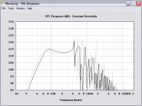
I have tried it and here is a post to see what you get with the same drivers in a sealed box. Lets make it 2 cubic feet or around 57 litres. It's easier to use a computer to knock about designs than to make them and then measure them. Power in is 50watts.
An externally hosted image should be here but it was not working when we last tested it.
Your maximum level is 105 db no matter how power you pump in. It's limited by the cone area and the stroke of the driver. A horn or in the case of the UNHORN gives you a more efficient coupling to the air around the box and in the room or in this case the car. To understand it simply think this through. If you ever tried playing a trumpet or some other brass instrument or woodwind you don't make alot of noise in the mouth piece. But put the mouth piece on the horn and voila you have a lot bigger sound. Same principle with a horn loudspeaker or a Tappered Quarter Wavelength Resonator which is what the UNHORN really is.
If you want lower (as I do) keep watching . I'm working in the shop right now on a set of three. Home version of the unhorn. True TRIO 8 18hz tapped horn and dual SDX7 18hz UNHORN box. Have to finish this stuff eventually.
Mark
EDIT
And if that graph is in half space, in my experience with hatchbacks, you'll get roughly a 12dB/octave gain from 60Hz down, and a static 9-12dB gain across the board. So if that graph is of it's half space response, then the sealed box could very well be louder in that hatch. Try it 😉
Also those two drivers are tapped at different lengths on the horn..."If you ever tried playing a trumpet or some other brass instrument " with two mouthpieces at different entries into the horn path? Nope haven't tried that one...But playing Brass and Woodwinds with traditional mouthpieces, yes I've done that.
And if that graph is in half space, in my experience with hatchbacks, you'll get roughly a 12dB/octave gain from 60Hz down, and a static 9-12dB gain across the board. So if that graph is of it's half space response, then the sealed box could very well be louder in that hatch. Try it
Hi Judttoff
Your right 2 cubes is big. But it gives a decent low end. and the graph is for illustrative purposes. Not a serious closed box design to optimize size. No mater how you change the box you can't get a lot louder. Whereas the horn gives you an extra 8db of gain. Go figure the power return on that. If you start SPL at say 10 watts you need 10 * 2 = 3db (20Watts) +
20 * 2 = (40Watts) + 40 * 2 = 80 watts. It is an illustration of what gain from a properly designed box can offer. The output of 80 watts power for an input of 10 watts. Not to bad.
In a 1/8th space the graph would go up by 3 db overall. You will gain some loading in the low end as you state. You do know something about car audio!
The point of the horn design is to get the most bang for the buck. There is no free lunch. Hi efficiency means narrow bandwidth. Therefore you can get 108db/watt in a car environment or 1/8th space.
But you only get usable output from 35 to 140 hz. Two octaves. Those two octaves are where most bass music exists and that's why it was designed this way. It is also a tiny box. Again part of the design goals. I have fully horn loaded designs that are a fairbit bigger and even more efficient. But this is not the pupose of this thread.
The impedance matching is evident in the change of Fs and the second impedance rise. You get the low end resonance of the horn and the upper resonance of the horn caused by the driver at the second tap point. I didn't post those graphs but if you know your horn design you will understand this concept. The driver out of the horn measurement was shown and the driver in the horn was shown. As was a detailed 5hz increment SPL measurement. Without any smoothing or marketing crap. There is nothing to hide behind smoke and mirrors. This really works and runs well of my head unit. No amp. Another reason for wanting high efficiency.
Cons? The drivers are not cheap. But they perform very well. If you want to pour in the power you have already quoted the max SPL. There have been a couple of cheaper alternatives posted. They do compromise the design in terms of output. But they are considerably cheaper. If you want to try it go ahead.
Otherwise thankyou for your encouragement.
Mark
The thing is, a car is Not eighth space. Again, instead so speculating that your so called horn is more efficient than the sealed box, test it out. Prove me wrong. Preferably use a .5cuft box with the two drivers to get a Q of .7. It's not that much wood, or time to build it.
I've looked at your measured impedance graph, all I see is a 6th order bandpass. Not really any horn action going on.
We need some response graphs in half space of your horn, to compare with the Hornresp response, I bet they are nothing alike. Then you could compare it fairly with other designs.
I've looked at your measured impedance graph, all I see is a 6th order bandpass. Not really any horn action going on.
We need some response graphs in half space of your horn, to compare with the Hornresp response, I bet they are nothing alike. Then you could compare it fairly with other designs.
Mark,
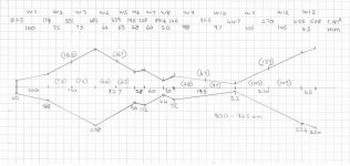
First, an apology: I thought you used 3/4" HDF, but you used 5/8". You have a picture in post #31 with a ruler showing the thickness, and you also mentioned the thickness in post # 72. As well as "measure twice, cut once" I also need to "read twice, post once".
Second, I have managed to draw a plan of the box that matches your photos. Lots of orthographic correction, printing and measuring...
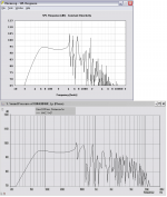
Armed with the measurements off the plan, I have modeled both your original Hornresp design, and the "as built" box, in Akabak.
The original design model results match closely between Hornresp and Akabak. I would expect this, because Hornresp can export a design suitable for importing in Akabak, but it was a good sanity check. (Note that Hornresp will not export an Akabak model of this design because Hornresp models converging horn sections differently than Akabak.)
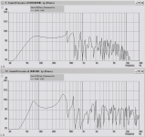
The "as built" model, however, produces results very different than the design model. The peak you noticed when measuring in your car is there too. It appears that the compromises you had to make (folds, flat panels, non-coincident drivers etc) have had their effect.
None of which is news, of course, and not intended as criticism of you. I emphasise that I would not be able to do better under the same constraints. All kudos to you for building it, we can model until we die but that is no substitute for making sawdust and seeing how it works in the real world. I look forward to your experiences with the new 2x DX7 box, it looks as if it will require fewer compromises.
I've learned a lot from this thread already, I hope to learn much more in future. It spurred me to research widely, and I even found a technique for cheaply and easily producing rectangular cross section horns with curved sections, which would have eased your design constraints. I'll post it in a new thread and post a pointer to it.
Regards...
First, an apology: I thought you used 3/4" HDF, but you used 5/8". You have a picture in post #31 with a ruler showing the thickness, and you also mentioned the thickness in post # 72. As well as "measure twice, cut once" I also need to "read twice, post once".
Second, I have managed to draw a plan of the box that matches your photos. Lots of orthographic correction, printing and measuring...
Armed with the measurements off the plan, I have modeled both your original Hornresp design, and the "as built" box, in Akabak.
The original design model results match closely between Hornresp and Akabak. I would expect this, because Hornresp can export a design suitable for importing in Akabak, but it was a good sanity check. (Note that Hornresp will not export an Akabak model of this design because Hornresp models converging horn sections differently than Akabak.)
The "as built" model, however, produces results very different than the design model. The peak you noticed when measuring in your car is there too. It appears that the compromises you had to make (folds, flat panels, non-coincident drivers etc) have had their effect.
None of which is news, of course, and not intended as criticism of you. I emphasise that I would not be able to do better under the same constraints. All kudos to you for building it, we can model until we die but that is no substitute for making sawdust and seeing how it works in the real world. I look forward to your experiences with the new 2x DX7 box, it looks as if it will require fewer compromises.
I've learned a lot from this thread already, I hope to learn much more in future. It spurred me to research widely, and I even found a technique for cheaply and easily producing rectangular cross section horns with curved sections, which would have eased your design constraints. I'll post it in a new thread and post a pointer to it.
Regards...
The "as built" model, however, produces results very different than the design model. The peak you noticed when measuring in your car is there too. It appears that the compromises you had to make (folds, flat panels, non-coincident drivers etc) have had their effect. None of which is news, of course, and not intended as criticism of you. I emphasise that I would not be able to do better under the same constraints. All kudos to you for building it, we can model until we die but that is no substitute for making sawdust and seeing how it works in the real world. I look forward to your experiences with the new 2x DX7 box, it looks as if it will require fewer compromises.
Hello Don
You sure went through a great deal of work. Probably more than me even!
You have uncovered the difference between a simulation and a prototype. As measured in post #102 by Adam ( Binary110) and his cousin:
The bass is pretty much as flat as i have heard it. Sittin in car me and the other guys were lookin at the SPL meter playing test tones in increments from 40hz to 100hz, the dB meter never swayed more than 2 dB up or down from our baseline. The car did have a hell of a resonance around the 75-80hz range, the car was rattling a bit, but thats got nothing to do with the sub, but the cabin size/resonances of the Toyota Matrix.
My measurements were done i the car with a different setup. The back seats were up the mouth of the horn was shooting into the middle of the car. When the three of us took a whack at it I had one seat folded down to get access to the box, the mouth was pointed to the rear hatch and the response was almost flat. Obviously moving around in any measurement space will affect the results of the measurement.
But in your defense Don the design is not totally faithful to the proper layout. The last three that I did have been almost exact replicas. But they are larger as you alluded to. A box this small is not easy to create. But it could be tweeked a bit to match almost precisely. Hindsight is always 20/20. I redid the design using conic paths only and it makes it much easier to work with. In a horn that handles only bass there is no real life benefit to using curves. There are only benefits up and above 350hz. Not a hard and fast rule but it has proven true for the most part.
Now you have me interested in whether or not you drew the design as I have. I found the original full scale template. So other than the 1/8th inch difference on the thickness of the material it is the original layout.
It is probably a fair statement that this design has been one of the few thoroughly measured and reviewed horns in recent memory. And a few gents have been there to push things in the right direction despite my being a bit naieve on the software end at times. GM and Bjorno are owed a debt of thanks and Don you are the only person I know of who took the time to do some real thinking. Good on you man!
Mark
P.S. Looking forward to your thread Don
mwmkravchenko said:
My measurements were done i the car with a different setup. The back seats were up the mouth of the horn was shooting into the middle of the car. When the three of us took a whack at it I had one seat folded down to get access to the box, the mouth was pointed to the rear hatch and the response was almost flat. Obviously moving around in any measurement space will affect the results of the measurement.
You're right. Given the small dimensions of a car at the wavelengths concerned you would not think a few inches would make a difference, but they do. I've seen 10 dB difference, measured at the standard SPL contest measuring microphone location, caused simply by rotating the subwoofer enclosure 90 degrees. We got 12 dB more in a small hatchback by moving the sub from its forward facing position so it faced into one of the back corners. It sounded much worse for music, but music has nothing to do with SPL contests...
In a horn that handles only bass there is no real life benefit to using curves. There are only benefits up and above 350hz. Not a hard and fast rule but it has proven true for the most part.
Look at the bottom corner of your box, after the decreasing section turns the corner. It expands to almost twice its size before starting to decrease again. I'll tweak my model so that the size does not increase, then see if it improves the performance. If so, it indicates that using curves and fillers might be advisable in small boxes. In other words, bends / corners in long, thin pipes are not a problem. Bends / corners in short, fat pipes might be a problem.
Now you have me interested in whether or not you drew the design as I have. I found the original full scale template. So other than the 1/8th inch difference on the thickness of the material it is the original layout.
I'll tidy up the drawing, scan it and post it along with the Akabak scripts.
It is probably a fair statement that this design has been one of the few thoroughly measured and reviewed horns in recent memory.
Indeed it has. This is because it challenges our preconceptions - we "know" what a tapped horn should look like, then along comes the Unhorn. It makes us think " how does this work?". I know I wouldn't have attempted such a design because I "just knew" it wouldn't work. But then I wouldn't have learnt as much as you have. Your tag line at the bottom of your posts sums it up well.
Hi Don
It really is a strange thing to listen to such a small box produce bass. I modeled it and thought exactly the same thing. It can't work right? But then the urge to give it a shot won out. It is not really a horn in some ways. But in a confined space it behaves as modeled. Go figure. And it sounds good to boot!
I encourage people to give it a try you may be surprised. And as shown there is an entry level version possible.
Mark
Okay, here we go.
First, the picture of the box plan, as I measured from your plan and your photographs. I settled on about 11/16 (17 mm) as the panel thickness - your photo with the ruler showed 0.68 inches.
The 5/8" HDF appears to have a laiminate surface which would account for the difference. Using 17 mm, everything fell into place.
I know it seems pedantic to be worrying about millimetres at these wavelengths, but they do add up by the time you get to the throat of the last sections.
Attachments

Now, here are the SPL plots from your original Hornresp model and the corresponding Akabak model. Note the similarity.
Also, here is the Akabak script corresponding to your original model.
|----------------------------
Def_Driver 'CSS SDX7'
SD=128cm2 |Piston
fs=34Hz Mms=21.9g Qms=2.2
Qes=0.41 Re=6.4ohm Le=0.75mH ExpoLe=0.618
System 'Unhorn As Designed'
Driver 'D1' Def='CSS SDX7' Node=1=0=11=13
Driver 'D2' Def='CSS SDX7' Node=1=0=11=13
Waveguide 'W1' Node=10=11
STh=85cm2 SMo=556.21cm2
Len=24.2cm T=1
Waveguide 'W2' Node=12=11
STh=21cm2 SMo=556.21cm2
Len=42.8cm T=1
Waveguide 'W3' Node=12=13
STh=21cm2 SMo=302.28cm2
Len=16.4cm Conical
Horn 'H4' Node=13
STh=302.28cm2 SMo=305cm2
Len=0.1cm Conical
|----------------------------------------
Attachments
Now we get to the heart of the matter. The attached image is the SPL plot from the "as built" Akabak model, again compared against the original design model.
The following Akabak script is for the "as built" model.
|-------------------------------
Def_Driver 'CSS SDX7'
SD=128cm2 |Piston
fs=34Hz Mms=21.9g Qms=2.2
Qes=0.41 Re=6.4ohm Le=0.75mH ExpoLe=0.618
System 'Unhorn As Built'
Driver 'D1' Def='CSS SDX7' Node=1=0=12=21
Driver 'D2' Def='CSS SDX7' Node=0=1=19=14
Waveguide 'W1' Node=10=11
STh=81.3cm2 SMo=179cm2
Len=100mm Conical
Waveguide 'W2' Node=11=12
STh=179cm2 SMo=331cm2
Len=75mm Conical
Waveguide 'W3' Node=12=13
STh=331cm2 SMo=484cm2
Len=75mm Conical
Waveguide 'W4' Node=14=13
STh=339cm2 SMo=484cm2
Len=64mm Conical
Waveguide 'W5' Node=15=14
STh=195cm2 SMo=339cm2
Len=63mm Conical
Waveguide 'W6' Node=15=16
STh=195cm2 SMo=228cm2
Len=28mm Conical
Waveguide 'W7' Node=17=16
STh=89.4cm2 SMo=228cm2
Len=60mm Conical
Waveguide 'W8' Node=17=18
STh=89.4cm2 SMo=146cm2
Len=30mm Conical
Waveguide 'W9' Node=19=18
STh=95.5cm2 SMo=146cm2
Len=98mm Conical
Waveguide 'W10' Node=20=19
STh=44.7cm2 SMo=95.5cm2
Len=97mm Conical
Waveguide 'W11' Node=20=21
STh=44.7cm2 SMo=270cm2
Len=105mm Conical
Waveguide 'W12' Node=21=22
STh=270cm2 SMo=455cm2
Len=105mm Conical
Waveguide 'W13' Node=22=23
STh=455cm2 SMo=508cm2
Len=45mm Conical
Radiator 'Rad1' Def='W13' Node=23
x=0 y=0 z=0 HAngle=0 VAngle=0
|-------------------------------
Attachments
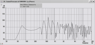
You said at one point that you were not getting the SPL you were expecting. Also, it was not clear how you had wired the two drivers up. At one point you said you had wired them + to -, - to +, which would put them in phase. In another post I read it as if you had wired them + to +, - to -, which would put them out of phase. You also posted a recent picture with yellow arrows, and accompanying text, that implied the drivers were wired out of phase (one cone pushing in as the other pushed out.) So I reversed the phase of one of the drivers in the simulation, and came up with the attached plot. As you can see, it doesn't look a lot different from the first plot, except the SPL is lower.
In short, if it sounds OK but you aren't getting the SPL you expect, check the wiring. You might have them wired out of phase... 🙂
In short, if it sounds OK but you aren't getting the SPL you expect, check the wiring. You might have them wired out of phase... 🙂
Attachments
Summary:
Well, this has been educational. I've learnt more about Akabak, and opened up a couple of areas of investigation:
- I've come up with a construction method for simplifying small bass horn construction and allowing constant radius bends. I'll start a new thread with it.
- I'm going to investigate one of the ideas of the Unhorn design, namely multiple drivers at different positions on the pipe. There is no free lunch, but it might be possible to balance out response irregularities caused by shorter than optimum pipe length. It might also allow smaller than optimum internal volume, so that 2 drivers do not require twice the pipe volume. Hoffman's Iron Law still applies, but modern drivers such as the DX7 make the compromises more acceptable. The ideal goal would be a significantly smaller than usual cabinet that has a flat response, so doesn't require equalisation.
(Or, for car use, has a 12 dB/octave falling response that nicely matches cabin gain.)
By the way, I strongly recommend coming to grips with Akabak.
I know it has a reputation as being hard to learn, but you don't have to learn it all at once. At its most basic, it is no harder to use than any other box modelling program. I wrote an "Akabak for Dummies" guide that will get you up and running, it's in this thread:
http://www.diyaudio.com/forums/showthread.php?s=&threadid=90362
And if all you want to do is look at the scripts I posted:
- Download and unzip / install Akabak.
- Start Akabak.exe
- Select File --> New Script
- Paste in the script I posted above
- Select Sum --> Acoustic Pressure
- Press OK
- Voila.
Check the "Sum" and "Inspect" menus for other graphs.
Regards...
WOW!
Well Don you sure don't fool around.
I have but a few comments.
The null in response is real if you have both drivers wired in same polarity. If they are wired in opposite polarity as described in the wiring instructions the horn works better.
http://www.diyaudio.com/forums/showthread.php?postid=1863176#post1863176
And one other thing you have definitely inspired me to try AkaBak. It is not bang on but it can be tweeked to your hearts content. So off I go.
I have been working like a dog the lst couple of days so that's why you got no reply. But I will work on some of the cabinets on the weekend to see what is going on with them. They are being built up to millimeter accuracy. So we will see what is going to happen.
I also have my software up and running and I will do some real measurements instead of the Radio Shack SPL meter method.
Mark
Well Don you sure don't fool around.
I have but a few comments.
You said at one point that you were not getting the SPL you were expecting. Also, it was not clear how you had wired the two drivers up. At one point you said you had wired them + to -, - to +, which would put them in phase. In another post I read it as if you had wired them + to +, - to -, which would put them out of phase. You also posted a recent picture with yellow arrows, and accompanying text, that implied the drivers were wired out of phase (one cone pushing in as the other pushed out.) So I reversed the phase of one of the drivers in the simulation, and came up with the attached plot. As you can see, it doesn't look a lot different from the first plot, except the SPL is lower.
The null in response is real if you have both drivers wired in same polarity. If they are wired in opposite polarity as described in the wiring instructions the horn works better.
http://www.diyaudio.com/forums/showthread.php?postid=1863176#post1863176
And one other thing you have definitely inspired me to try AkaBak. It is not bang on but it can be tweeked to your hearts content. So off I go.
I have been working like a dog the lst couple of days so that's why you got no reply. But I will work on some of the cabinets on the weekend to see what is going on with them. They are being built up to millimeter accuracy. So we will see what is going to happen.
I also have my software up and running and I will do some real measurements instead of the Radio Shack SPL meter method.
Mark
I've been giving thought to car sub implementations. Any car sub has to allow for cabin gain. This is different for every car model, and one of the challenges is to come up with a simple, repeatable and universally applicable method of measuring cabin gain for any car.
However, for research purposes all I need is an approximation that I can apply to a design to determine if it will play well enough in a car to be worth developing further. Further up the thread, Eva suggested a good default curve for a car sub: "Flat down to 80 Hz, -3dB at 60 Hz, another 12 dB down at 30 Hz, and 24 dB/octave slope from 30 Hz down." This approximates to a cabin gain with F3 at 60 Hz and a Q of about 0.6. I've applied it against a few designs, and it passes the common sense test. If a design fits this curve, it can likely be tweaked to suit most real cars.
I've been using the Unhorn specs (2x CSS SDX7, 27 litres) as a starting point to see what works well and what doesn't. This has the advantage that the results can be compared with the Unhorn, to explore the argument that a more conventional box will do as well as an Unhorn in a similar enclosure size.
I set 3 initial criteria:
- The enclosure should be a similar size to the Unhorn.
- The response should be a good match to Eva's curve.
- A better SPL than a sealed box, and the lower the power required to reach max SPL (=Xmax), the better.
The initial results are that a 2x SDX7 sealed box won't perform well in the "Eva" car. The rolloff curve is a poor match for the cabin gain curve for any reasonable box size.
The Unhorn isn't a great match either, it has a 24 dB/octave initial rolloff. It does do a lot better than the sealed box in the SPL stakes.
So far, the best performer is a ported enclosure. Not a standard alignment, but one that is too small and tuned too low. 2x SDX7s, 24 litres, tuned to 25 Hz. In the theoretical car it's flat down to 21 Hz at full power. But it's not a winner, because the required port is too long to be practical. It's 10 cm diameter, and about 1.4 metres long. Even if folded it would require 14 litres of space, making the total space requirement about 40 litres. And the port resonance is only 132 Hz, requiring a sharp cutoff sub crossover.
What the design does show is quite an unusual response curve. I'll try to apply the design points (too small and tuned too low) to a tapped horn configuration and see if I can duplicate the curve. If I end up with something that looks a bit like the Unhorn, I will not be surprised. 🙂
I'm not so sure it's really important to try to exactly match the cabin gain curve. Even if you wanted to try to match it, under which conditions would it be appropriate to measure?
I would guess that the majority of in car measurements will be taken sitting still, probably with the engine off. This will produce vastly different results than measuring at 100 mph with the windows open. The noise floor under those conditions will mask your bass, the lower the bass the more the road noise will kill it. Unfortunately I can't prove this with measurements at this time since I haven't had the opportunity to measure while driving, so ymmv.
I wouldn't want to design a car sub to lose any more than about 6 db/oct below 80 hz but that's just me. It might be a bit bass heavy sitting in the driveway but at least there will be recognizable bass on the highway.
Last edited:
Road noise curves vary by vehicle and road surface, but typically peak at about 50 Hz and slope downwards at about 6 dB / octave as the frequency increases. The level is also vehicle speed dependant. There is no one bass boost curve or amount that will fit all scenarios. Ideally, you would have an equaliser that samples vehicle noise and boosts the bass to compensate. But even if you do it manually, you need to match the bass boost control response to the system response. If your initial response is flat, then a simple Baxandall style bass boost control will suffice. If your response isn't flat to start with, you need a complex boost curve. In summary: 1) Get it right when at rest. 2) Make sure there's enough headroom (amp power, driver xmax) to handle the amount of boost needed to bring the response up to a perceived "flat" at the speeds you habitually drive at when listening. This can be 20 dB or more unless you own a high-end luxury car and/or have invested heavily in damping.
Mark,
I've been working with your original design profile, where the horn profile tapers down to the middle and then expands out again - a "bowtie" profile when viewed in Hornresp schematic. (Or a "genie bottle" when viewed sideways). It showed some promise for an "in car" response curve.
I find that many of my designs end up with a very small "neck" section. The air velocity through the neck is way too high and would cause "chuffing" at high excursions. I looked at your "as built" Unhorn, and the air velocity through the neck at max excursion is over 40 m/sec - about twice the commonly suggested maximum. I would expect it to make some "port" noise at high volumes. Your original HormResp schematic was even worse, with a neck area only half that of the "as built" design.
It's something to watch out for. If you export a Hornresp design into Akabak, you can use the "Inspect --> Velocity" tool to measure the velocity at any node in the horn.
Regards,
Mark,
I've been working with your original design profile, where the horn profile tapers down to the middle and then expands out again - a "bowtie" profile when viewed in Hornresp schematic. (Or a "genie bottle" when viewed sideways). It showed some promise for an "in car" response curve.
I find that many of my designs end up with a very small "neck" section. The air velocity through the neck is way too high and would cause "chuffing" at high excursions. I looked at your "as built" Unhorn, and the air velocity through the neck at max excursion is over 40 m/sec - about twice the commonly suggested maximum. I would expect it to make some "port" noise at high volumes. Your original HormResp schematic was even worse, with a neck area only half that of the "as built" design.
It's something to watch out for. If you export a Hornresp design into Akabak, you can use the "Inspect --> Velocity" tool to measure the velocity at any node in the horn.
Regards,
Hello Don
First off I apologize for the long time in posting a reply. I seem to have been knocked off the wagon as to post notifications. And paying work has taken the front seat this month.
In practical experience it can get a little chuffing but it happens only when the box is being driven below it's useful pass band. It is not that noticeable even on high power sine waves where I would think that it would be most irritating. I am quite familiar with ported enclosures that have port packing noises. They drive me nuts. One of the reasons I designed this little baby. So I will mess about with this and see what I can come up with. On empirical evidence only I can say that I don't get any of the chuffing problems. That's being driven at 114db and sitting within 1/2 a meter of the enclosure.
The hour glass shape it what works out every time you try to radically shrink a box to useful size. As this is neither a true tapped horn nor a transmission line. It is more like a double tuned double tapered voight tapered pipe. Double tuned in that it is driven from two points. When you move the driver around in the simulations you can get some interesting results.
I am still amazed at the results that come out of AkaBak as to the low end drop off for the enclosure. Not a very good match. But Hornresp was much closer. Still learning some new tricks.
Mark
Hi Mark,
Work comes first, otherwise we cannot afford to play. 🙂
Regarding port noise, the tapering of the "port" likely helps to reduce port noise in the same way that flaring a port does.
I agree, the hourglass or bowtie shape is what you get when you combine chamber (Helmholtz) resonators with 1/4 wave resonators. The aim is to get the best of both in the same box - a true reflex. This is an old use of the term "reflex", from the early days of "steam" radio when tubes / valves were expensive. It was quite common to use one tube to amplify the RF signal, then after conversion to AF the signal would be fed back through the same tube again to amplify the AF (audio) signal. In this case, we're using the same box both as a Helmholtz resonator and as a pipe resonator.
I am surprised that you see a significant difference in the low frequency response between the Hornresp simulation and the Akabak simulation. I have just compared the two and they agree to less than 1 dB. (Relative response, not absolute dB SPL, because I used different input voltage.) And I believe David has said that Hornresp and Akabak use the same modelling techniques, so the results should be the same. If they are not, then you should look for differences in the input parameters.
One thing I missed before, your original Hornresp input parameters in post #43 show a large chamber defined between the driver(s) and the "S2" point of the horn. Is that intentional? This may explain the response difference you see. The attached picture shows a Hornresp graph with the chamber (grey line) and without (black line). There is a significant difference. The black line version exactly matches my Akabak model, which does not have the chamber.
There certainly are a number of options to juggle when trying to optimise this type of enclosure. For example, Hornresp cannot accurately model your "as built" design because the "mouth ends" of the two drivers are not at the same place - one is before the "port", one is after. Akabak allows modelling this, and the response curves are quite different.
I'm currently working on using two drives to complement each other. Often, the most afficient (highest SPL) )configuration results in a peak at the LF limit, then a dip, then another peak an octave higher. I'm trying to make the second driver "fill in" the dip. Troels Gravesen does something similar with his "doppel horns", where two tapped horns are tuned a fifth apart. It's harder to do it in a single horn.
Attachments
- Status
- Not open for further replies.
- Home
- Loudspeakers
- Subwoofers
- Tapped Horn For Car