Hi Bjorno
Your post revealed but a small mistake in the math added to clarify the graph that was correct anyway. I appreciate your diligence.
Do you have actual measurements of the driver or are you using factory specs?
X-mechanical is 18mm so even as you know that X-max plus 10% will still give reasonably low distortion in a conventional box. A little over excursion in a horn is allowable as well. SO your design is both accurate and conservative.
I forgot to post the constant voltage source is a normal well designed amplifier up to it's rated power. They are designed to send a constant voltage into a speaker load. As the load varies wildly close to resonance it becomes less constant as the current limit of the amplifier is reached. So again a conservative design and specification is best.
Mark
Do you have actual measurements of the driver or are you using factory specs?
Hi Mark,
I use the TRIO8 factory specification but it doesn't hurt to do a consistency check and choose slightly different parameter values than advertised.
Nowadays I mostly use MJK:s neat BL and VAS consistency checking programs + quite a bunch of other programs of other designs or of my own.
b
The specifications I posted are measured if it is of any use. I now use the woofer tester 3. Wonderfully simple little box to use. Beets the hell out of the old methods of scope plus function generator plus counter plus voltmeter. Now click and wait a whole second. THe work is just horrendous!
Mark
Mark
Hi there, just read the whole thread.
I also like clean low bass, with a flat response, and in the many boxes I've built I've had good luck with 4th order bandpasses(for a flat response). Anyways my setup is a little more insane, I might be one of those morons that listens to rap.
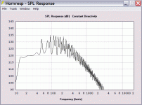
Anyways 114dB with 2 7" drivers and what 22wrms? That's pretty good, but I think you can do better. You would likely get a similar response from those 2 drivers sealed(as the inner most one contributes virtually nothing to the output). Maybe try it out and see!
If you feel like making some sawdust, perhaps try mounting your two subs parallel to each other, making the box necessarily twice as wide. Obviously you will need to shift some other parameters. Maybe make the path length longer so you can dig down lower...
But I'm glad to see another Canadian playing around with tapped horns 😀 I wish my one would fit in a car....but it's about 14cuft external...It's 1/4 wave length is about 19.5Hz 😀
I also like clean low bass, with a flat response, and in the many boxes I've built I've had good luck with 4th order bandpasses(for a flat response). Anyways my setup is a little more insane, I might be one of those morons that listens to rap.
Anyways 114dB with 2 7" drivers and what 22wrms? That's pretty good, but I think you can do better. You would likely get a similar response from those 2 drivers sealed(as the inner most one contributes virtually nothing to the output). Maybe try it out and see!
If you feel like making some sawdust, perhaps try mounting your two subs parallel to each other, making the box necessarily twice as wide. Obviously you will need to shift some other parameters. Maybe make the path length longer so you can dig down lower...
But I'm glad to see another Canadian playing around with tapped horns 😀 I wish my one would fit in a car....but it's about 14cuft external...It's 1/4 wave length is about 19.5Hz 😀
Try it and you'll see! Right back at you !
Hi there judtoff
I have tried it and here is a post to see what you get with the same drivers in a sealed box. Lets make it 2 cubic feet or around 57 litres. It's easier to use a computer to knock about designs than to make them and then measure them. Power in is 50watts.
Your maximum level is 105 db no matter how power you pump in. It's limited by the cone area and the stroke of the driver. A horn or in the case of the UNHORN gives you a more efficient coupling to the air around the box and in the room or in this case the car. To understand it simply think this through. If you ever tried playing a trumpet or some other brass instrument or woodwind you don't make alot of noise in the mouth piece. But put the mouth piece on the horn and voila you have a lot bigger sound. Same principle with a horn loudspeaker or a Tappered Quarter Wavelength Resonator which is what the UNHORN really is.
If you want lower (as I do) keep watching . I'm working in the shop right now on a set of three. Home version of the unhorn. True TRIO 8 18hz tapped horn and dual SDX7 18hz UNHORN box. Have to finish this stuff eventually.
Mark
Anyways 114dB with 2 7" drivers and what 22wrms? That's pretty good, but I think you can do better. You would likely get a similar response from those 2 drivers sealed(as the inner most one contributes virtually nothing to the output). Maybe try it out and see!
Hi there judtoff
I have tried it and here is a post to see what you get with the same drivers in a sealed box. Lets make it 2 cubic feet or around 57 litres. It's easier to use a computer to knock about designs than to make them and then measure them. Power in is 50watts.
An externally hosted image should be here but it was not working when we last tested it.
Your maximum level is 105 db no matter how power you pump in. It's limited by the cone area and the stroke of the driver. A horn or in the case of the UNHORN gives you a more efficient coupling to the air around the box and in the room or in this case the car. To understand it simply think this through. If you ever tried playing a trumpet or some other brass instrument or woodwind you don't make alot of noise in the mouth piece. But put the mouth piece on the horn and voila you have a lot bigger sound. Same principle with a horn loudspeaker or a Tappered Quarter Wavelength Resonator which is what the UNHORN really is.
If you want lower (as I do) keep watching . I'm working in the shop right now on a set of three. Home version of the unhorn. True TRIO 8 18hz tapped horn and dual SDX7 18hz UNHORN box. Have to finish this stuff eventually.
Mark
I missed your comment about the second driver
The second driver gives you an extra 3db or double the effect of a single driver. Take a look at the pic below. As one driver pushes onto the chamber the other is pushing out at a midway tap point. You get the effect of a much longer horn for the low-end cutoff than you would any other way. Without this driver in this box you get a pretty sad output. Together it is quite impressive as the young lads mentioned.

Mark
P.S. I laid out one of the horns and the others are being worked on a bit more tonight when I go back to the shop. ( it's a long 60ft walk to the shop from my house. )
The second driver gives you an extra 3db or double the effect of a single driver. Take a look at the pic below. As one driver pushes onto the chamber the other is pushing out at a midway tap point. You get the effect of a much longer horn for the low-end cutoff than you would any other way. Without this driver in this box you get a pretty sad output. Together it is quite impressive as the young lads mentioned.
Mark
P.S. I laid out one of the horns and the others are being worked on a bit more tonight when I go back to the shop. ( it's a long 60ft walk to the shop from my house. )
I have some Tang Band W6-1139SI's, can they be substituted for the SDX7? They have a 13mm xmax.
Try them out if you like
The design is quite specific.
I modeled a couple of cheap drivers a few posts ago. You generally loose low end or efficiency.
But it does not try to hurt. Or hurt to try.
Mark
The design is quite specific.
I modeled a couple of cheap drivers a few posts ago. You generally loose low end or efficiency.
But it does not try to hurt. Or hurt to try.
Mark
A bit of modeling and....
Hi 85audio
You can expect 3db less efficiency or half of the SDX drivers.
At 100 watts you can actually get a bit louder. The drivers suspension is much more stiff than the SDX7.
So all in all it is not a bad fit if you have the power. Mine runs on less than 10 watts most of the time. That's the reason I went this route. Clean and efficient. Runs off my head unit. Until I finish the next version. Then I will have another one to sell. Right now I'm working on some other boxes. Paying customers come first!
Mark
Mark,
I've been trying to lay out the box according to your instructions in the drawing and the accompanying post, by marking points on one of the 16.5 x 13.25 inch side sheets. It simply doesn't work out. The points don't add up. It's as if you took your dimensions by measuring your prototype. The problem appears to be that you have specified 1/2" sheet on the plan, but you have built your prototype with 3/4" sheet. It's also not clear if some of your measurements are from the edge of the sheet or from 1/2" (or 3/4") in from the edge to allow for the thickness of the sheets.
Can I assume that the dimensions are supposed to follow the dimensions on the Hornresp simulation? You have:
S1 = 85 cm2 = 8" x 1 5/8" (plan says 1 9/16")
S2 = 556.21 cm2 = 8" x 10 3/4" (plan says 9 3/8")
S3 = 21 cm2 = 8" x 3/8" (plan not clear, appears to be 1")
S4 = 302.2 cm2 = 8" x 5 7/8" (plan not clear)
S5 = 305 cm2 = 8" x 5 15/16" (plan not clear)
Based on the above, the critical dimension appears to be the S3 point. Working from the plan, it is almost impossible to get the dimension correct. Everything needs to be adjusted to get the gap correct. The S3 gap appears to be set between the "peak" of the pieces forming the S2 point, and the diagonal filler in the corner of the box. The diagram incorrectly imples it is set between the "peak" and the side of the box.
Can you please shed some light on this for me?
Thanking you in anticipation...
Mark thanks for modeling that, I have 16 of the Tang Band drivers brand new in their boxes. It would be fun to put them to use. I built one of Volvotreter's 30Hz TH's that use this driver. It seems like it needs a lot of power. I powered it with a Parts Express 1000 watt plate amp. It does suprisingly well. But of course bottoms when pushed. So I built, I think Don Brunce's TH with a Lab sub(I bought 2 lab subs, wanting to build the lab sub some day but haven't because of the compound angles, but have recently bought a awsomely accurate Mikita chop saw that leaves me no excuse). Anyway, Don's sub rocks, but I feel that just when it starts to have the SPL I like, the amp clips and the box sounds maxed. I built the SPUD and think that it has better sound quality, maybe not as much SPL as Don's box. I keep waiting for a 1 end all boxes sub, then I can start to make multiples. I am curious to see if you and GM come up with a cinemaster sub plan. I was wondering if you do, would it be possible to interchange the Pyle Driver and the original B&C driver? Shaun
An externally hosted image should be here but it was not working when we last tested it.
Here is the best version.
I actually copied it off of my full scale drawing that I did in 12mm plywood.
An externally hosted image should be here but it was not working when we last tested it.
If I still have the original drawing I can do it. If I don't I'll draw it up again.
If you need piece by piece measurements I think I can still do that.
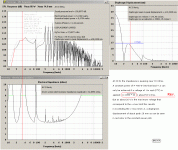
The box is a compromise on the Hornresp calculation as Bjorno pointed out. But it is not that comprimised! THe locations for the drivers were fudged in order for them to fit in such a small enclosure.
Mark
Thanks, Mark.
I've taken a fresh look, and you do indeed use 19mm (3/4") sheet for the various partitions, not 12mm as stated on the plan. That is, the rectangular sheets you used for the two large sides of the box are 12 mm plywood, but the partitions are 19 mm HDF. (In an early post, you mentioned you used some HDF left over from another project.)
There's more proof on the plan - look at your measurments along the "top" edge. The total length is 16 1/2 inches.
8 5/8 inches from the opening to the start of the diagonal partition.
About 1 inch for the end of the diagonal partition (square on the hypotenuse...)
6 1/8 inches from the other side of the diagonal partition to the "outside" partition.
3/4 inch for the "outside" partition.
16 1/2 inches...
The difference between 1/2" and 3/4" sheet is significant when trying to set the S3 throat size correctly.
Anyway, thanks. I'll carry on for the moment and get back to you if I come up against any unresolvable contradictions. I do like to get the measurements right, I'm the sort of peron who measures with a micrometer, marks with a crayon, and cuts with an axe...
Armageddon - the final solution.........
Model number, please?
GM
85audio said:........bought a awsomely accurate Mikita chop saw that leaves me no excuse).
Model number, please?
GM
Hello Don
I checked in the shop this morning for the original full size drawing. I'still got it. From the data produced by hornresp the pinched off area should be 1 cm not 1 inch (2.54 cm) But as things worked out I used the inch. Had I kept to the original the difference was small in output. But the second impedance peak more or less matched the simulation.
If you need help I'll be back home later tonight. But I think your pretty resource full. If you want the raw data from Hornresp go to the schematic section click on file, export and then in the wizard set width to 20.32cm you have to change the far right boxes to uni and the resulting text file is what I used.
Just make sure your drivers will fit!
Mark
Armageddon - the final solution.........
Hmm, to my way of thinking a true 'Cinemaster' sub would require a path-length approaching DC (infinity) terminating into a full size ~28.3 Hz mouth, so to paraphrase 'Dirty' Harry Callahan, you have to ask yourself just how serious are you, space, cost, time wise? I'm thinking, not very. 😉
At a more realistic level, multiple long path-length, but relatively small, ultra-wide BW THs stacked and/or scattered around a decent size room should have no problem theoretically bringing the biggest/baddest IBs to their 'knees' SQ wise due to its much flatter phase response, directivity/room placement and only needing 'flea' power to reach nauseous levels. This would be a time consuming and fairly costly endeavor, but probably considerably less than what the best sub drivers for the intended BW plus their multiple kW amps require.
I say 'theoretically' since down low all that matters is moving enough air at low turbulence, so a compression sub-horn's superior phase response through at least its lower pass-band is moot. Ditto its low turbulence if the IB uses enough woofers to keep excursion low. Ditto it's superior directivity and multiple room positions since the room could be optimized for a single sub during its design. Ditto its gain BW since special drivers could be built, so in reality, much lower cost and maybe total bulk are probably the only advantages to using multiple THs.
At a glance, I envision built-in THs using massive, tapered false walls to both reduce 'slap' echo and eigenmode amplitudes with some terminating at floor level, some at ceiling level and some in-between in a Dr. Geddes's preferred layout. Several B&C 15TBX100 drivers appear to be one option (1 W, corner loaded sim), though I'm sure there's other (and hopefully cheaper) ones.
Just some thoughts from the deep fringe........
GM
85audio said:I keep waiting for a 1 end all boxes sub, then I can start to make multiples. I am curious to see if you and GM come up with a cinemaster sub plan.
Hmm, to my way of thinking a true 'Cinemaster' sub would require a path-length approaching DC (infinity) terminating into a full size ~28.3 Hz mouth, so to paraphrase 'Dirty' Harry Callahan, you have to ask yourself just how serious are you, space, cost, time wise? I'm thinking, not very. 😉
At a more realistic level, multiple long path-length, but relatively small, ultra-wide BW THs stacked and/or scattered around a decent size room should have no problem theoretically bringing the biggest/baddest IBs to their 'knees' SQ wise due to its much flatter phase response, directivity/room placement and only needing 'flea' power to reach nauseous levels. This would be a time consuming and fairly costly endeavor, but probably considerably less than what the best sub drivers for the intended BW plus their multiple kW amps require.
I say 'theoretically' since down low all that matters is moving enough air at low turbulence, so a compression sub-horn's superior phase response through at least its lower pass-band is moot. Ditto its low turbulence if the IB uses enough woofers to keep excursion low. Ditto it's superior directivity and multiple room positions since the room could be optimized for a single sub during its design. Ditto its gain BW since special drivers could be built, so in reality, much lower cost and maybe total bulk are probably the only advantages to using multiple THs.
At a glance, I envision built-in THs using massive, tapered false walls to both reduce 'slap' echo and eigenmode amplitudes with some terminating at floor level, some at ceiling level and some in-between in a Dr. Geddes's preferred layout. Several B&C 15TBX100 drivers appear to be one option (1 W, corner loaded sim), though I'm sure there's other (and hopefully cheaper) ones.
Just some thoughts from the deep fringe........
GM
Attachments

GM,the model # of the Makita miter saw is LS1013FL.When I was working on the SPUD I was using the DeWaLT 705 12" non-sliding miter saw,not much cut capacity.I wanted something that would crosscut the width of the SPUD panels accurately.I just Googled miter saw reviews and read reviews of various miter saws.I picked out a saw with a review I liked and that I could buy locally.That saw was the Makita dual compound miter saw LS1013.Home Depo carries them.When I went into Home Depo that weekend,they just happened to be having a sale on them,it was $400. It is night and day difference from the DeWalt 705. In the review it said the saw cut like glass,I thought we'll see.I was very impressed with the cut quality.That is how I would describe it also,cutting like glass.It comes with a nice blade.I think the build quality is very nice on this saw,it has a built in laser if you like that sort of thing.The Bosch sliding saw is supposed to be good also,but more money.The 10" sliding saws are lighter and supposedly smoother running.I am not an expert,but I like this saw. As far as the end all sub boxes,then making multiples,your right I should have put one of those happy faces after this comment.I just want something a few steps up from a SPUD,I could make multiple boxes.William Cowan had a TH design using the MTX 9515 that Danley uses, that seemed like the perfect box for me.But I couldn't turn the design into plans even though William gave me clues.400-2200cm^2,total length5.2M with front tap 500mm back from mouth. Thanks for the comments Shaun
OK, thanks. All things considered, since I already have a decent quality ~portable table saw with numerous added features that cost less (ignoring inflation), guess I'll just stick with the 'devil' I know.
Well, you could always build just one big built-in one with a single driver as used in the sim. 😉
Yeah, the 9515 sims (Xmax) freaking awesome in ~30 ft^3 using published specs........
GM
Well, you could always build just one big built-in one with a single driver as used in the sim. 😉
Yeah, the 9515 sims (Xmax) freaking awesome in ~30 ft^3 using published specs........
GM
Attachments
- Status
- Not open for further replies.
- Home
- Loudspeakers
- Subwoofers
- Tapped Horn For Car