Hello,
I have the following audio tubes for sale. More will be added from time to time. If you have any questions or would like a shipping estimate please feel free to PM me. Thank you.
For sale is a pair of
Amperex 6DJ8 ECC88 vacuum tubes.
$35 plus shipping. Both tubes were produced by Philips in their Heerlen, Holland plant and these pair of tubes have the code sequences of GAO delta9H3 and GAE delta2G4. Both tubes have been tested for shorts, grid leakage and emission on a restored and calibrated Sencore TC-142 tube tester. The results are as follows:
Shorts: PASS
Grid Leakage: PASS
Emission:
Tube 1:
Triode 1: 101%
Triode 2: 102%
Tube 2:
Triode 1: 101%
Triode 2: 102%
In addition these tubes have had a life test performed on it which entails reducing the filament voltage of the tube by one step and noting any significant reduction in emission performance. These tubes performed very well in this regard.
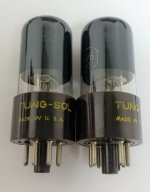
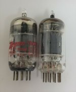
For sale is a pair of
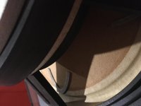
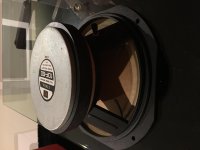
Tung Sol 6V6GT vacuum tubes.
$35 plus shipping. These tubes feature brown bases as well as smoked glass. They are in very nice shape save for a minor crack in both bases of the tubes. These can be seen in the first and second photo. These do not seem to affect the structural integrity of the tube. These tubes have been tested for shorts, grid leakage and emission on a restored and calibrated Sencore TC-142 tube tester. The results are as follows:
Shorts: PASS
Grid Leakage: PASS
Emission:
Tube 1: 90%
Tube 2: 91%
In addition these tubes have had a life test performed on it which entails reducing the filament voltage of the tube under test by one step and noting any significant reduction in emission performance. These tubes showed some reduction in emission but this reduction was not excessive.
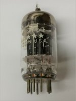
For sale is a pair of
General Electric 12AX7 ECC83 vacuum tubes.
$25 plus shipping. Both tubes, although the first is labeled Zenith, were manufactured by General Electric. These tubes have been tested for shorts, grid leakage and emission on a Sencore TC-142. The results are as follows:
Shorts: PASS
Grid Leakage: PASS
Emission:
Tube 1:
Triode 1: 101%
Triode 2: 100%
Tube 2:
Triode 1: 90%
Triode 2: 91%
In addition these tubes have had a life test performed on it which entails reducing the filament voltage of the tube under test by one step and noting any significant reduction in emission performance. The first tube showed no reduction in emission whereas the second showed some reduction but this was not excessive.
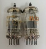
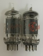
For sale is a pair of
General Electric 12AX7 ECC83 vacuum tubes.
$35 plus shipping. These tubes feature long, grey plates and halo getters. They have been tested for shorts, grid leakage and emission on a restored and calibrated Sencore TC-142. The results are as follows:
Shorts: PASS
Grid Leakage: PASS
Emission:
Tube 1:
Triode 1: 97%
Triode 2: 98%
Tube 2:
Triode 1: 99%
Triode 2: 99%
In addition these tubes have had a life test performed on it which entails reducing the filament voltage of the tube by one step and noting any significant reduction in emission performance. Both tubes performed excellently.
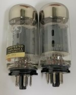
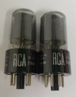
For sale is a pair of
RCA smoked glass 6V6 vacuum tubes.
$30 plus shipping. These tubes have the date codes of "57-43" and "58-30". These tubes have been tested for shorts, grid leakage and emission on a restored and calibrated Sencore TC-142. The results are as follows:
Shorts: PASS
Grid Leakage: PASS
Emission:
Tube 1: 92%
Tube 2: 98%
In addition these tubes have had a life test performed on it which entails reducing the filament voltage of the tube by one step and noting any significant reduction in emission performance. These tubes performed very well in this regard.
For sale is a pair of
Sovtek 5881/6L6WGC tubes.
$30 plus shipping. Although one of these tubes has been labeled by Mesa they were both manufactured by Sovtek in Russia. Both tubes have coin bases and two flying saucer getters. They have been tested for shorts, grid leakage and emission on a Sencore TC-142. The results are as follows:
Shorts: PASS
Grid Leakage: PASS
Emissions:
Tube 1: 93% Tube 2: 94%
Both tubes have had a life test performed upon them which involves reducing the filament voltage fed to the the tubes by one step on the tester and noting any drop off in emission. Both tubes did extremely well in this regard.
For sale is a
General Electric 5 Star 5751 tube.
$20 plus shipping. These 5 star series tubes were part of GE's "High Reliability" line that were manufactured to tighter tolerances and with better materials. This tube has black plates and has triple mica construction. It has been tested for shorts, gas and mutual transconductance on a Hickok 546. The results are as follows:
Shorts: PASS
Gas: PASS
Mutual Transconductance:
New = 1250 umhos
Tube 1: Triode 1: 1000 umhos Triode 2: 900 umhos
For sale is a
RCA 5751 tube.
$15 plus shipping. This tube has black plates and a halo getter. It has been tested for shorts, gas and mutual transconductance on a Hickok 546. The results are as follows:
Shorts: PASS
Gas: PASS
Mutual Transconductance:
New = 1250 umhos
Tube 1: Triode 1: 1000 umhos Triode 2: 1100 umhos