Tweed screen resistor

I just blew a tube in my DIY Tweed, probably playing at max volume for too long. I don't have 470 ohm screen resistors on the tubes so maybe that's why. I'm going to add resistors in there but I only have 680 ohm. Apparently 470 ohm to 1k can be used and it won't make any difference I but just wanted to ask to be sure before I put the 680 ohm in. Thanks for any advice.

NAD T762

Hello, hope I'm in the right place to post a problem with my NAD T762. Hopefully someone can help point me in the right direction.
It used to work real well, but started acting up. It would turn ON and then shut OFF (or go into protection) after several minutes of operation. I found the manual and schematics, however any assistance from any of you that may have experience with this amp would be greatly appreciated.
A quick visual check shows signs of electrolytic leaking on part of the main board, as well as this gummy yellowish glue that I understand turns conductive after several years. I took a quick check on the supply board and measured ±67VDC or thereabouts. Any ideas where I should begin?
Thanks for any ideas and direction. 🙂

KT88 mutual characteristics?

As part of my search for knowledge, I've also supplemented with Merlin's Valve Wizard site, specifically this page: The Valve Wizard -Single Ended

As part of calculating screen characteristics, he has mentioned the mutual characteristics graph from a particular valve. I've searched around a bit on KT88, and I've seen regular plate characteristic graphs for different screen voltages, but not quite illustrated this way, and he hasn't gone into any detail as to how to interpret this if you don't have the proper graphs.

Does anyone have these graphs for the KT88, or can point me to some reading for how to figure it out in a different fashion?

Heat sinks, TO-3 sockets

I've completed a preliminary design for a specialized power supply that is essentially a DC audio amp (output voltage +-50, output current +-5A). Now I'm trying to figure out what hardware I'll need.


I figure that the output transistors going at full tilt could dissipate as much as 150W, so I'm guessing that a heat sink good for about 300W should be a conservative choice. Where might I find such an animal? Any other comments?


Related: I want to use TO-3 sockets, since I'm using 2n3773 and 2n6609 output transistors. Newark Electronics has one for $1.22 in quantity that seems OK (https://www.newark.com/keystone/4602/transistor-socket-3-position-through/dp/35F1178). I also found a batch of bakelite sockets on Ebay that appear OK. Any suggestions?

Power cable shielding for messy entertainment centers

Hi All, I am looking for AC power cables with shielding and a good bit of insulation so that they can lay next to source interconnects with minimal interference. I know the best solution is to avoid running interconnects and power in parallel, but sometimes furniture, room layout and practicality conspire against us.

The affordable cable I've found with good insultation also seems to have shielding with large gaps. Depicted below. Is this a problem? Is this shielding doing any good? Would I be better off just getting a regular shielded power cable and putting some hose/tubing around it to force some distance between the AC power and interconnects?

Ue0df57e2fd604e64942af304b59123abJ.jpg


Thanks,
Joe

First build: ICE125ASX2? ICE50ASX2? L12-2?

I'm keen to build my first proper amp, to power a pair of M&K MPS-1510 speakers now perched on the corners of my desk (and currently powered by an FX502SPRO).


I've narrowed my choices down to the modules listed in the title: the L12-2 would be my first choice, in purely musical terms, if not for the fact that it seems way more difficult to build - with the need to find the right power supply, transformer, speaker protection.......and connect them all properly in the absence of an instruction booklet. The ICEpower modules are basically amps in a box, without the box. A buffer seems like the only thing I might want to add (?), other than a Ghentaudio box itself.


The ICEpower and L12-2 options would end up costing about the same, but there seems to be way less opportunity for disaster - electrocution, or (worse) damaging the speakers - with the former.


I'm unsure about several things related to the project:


Will the ICE50ASX2 have enough power to do justice to the M&K speakers? The FX amp seems to power them without too much trouble - turned to about "3" or "4", and running out of a FiiO E7 (?) DAC amplifier that's turned up fairly high. But will the speakers respond (in a good way!) to a lower signal from the DAC and more power from a - good quality - amp itself? The sonic results are ambiguous with the FX amp, but might be more obvious with a better one.....


Will the L12-2 project be substantially harder, for someone who still struggles to understand terms like "output impedence"? And speaking of output impedence: what does using a DAC-amp instead of a simple DAC mean for the issue of output impedance - should I be more concerned, or less? Does it make it more or less crucial (for sound quality) that I include an input buffer?


Finally: Given that I don't understand this, despite having read a half-dozen internet explanations, should I just save up an extra $50 and buy a pre-made ICEpower amp......?


Any advice gratefully received.

NAD T762

When using optical input #1 sound works fine but if you use OSD to switch to optical input #2 you get the sound from input #1. Also it seems to bleed over to coaxial #1 and #2 but not #3 or #4. Also none of the coaxial inputs will work or the optical #2. Confusing as hell. The digital input board is verified good. Since the digital inputs go to the DSP board next could that possibly be the problem?? Also all other features of receiver work properly.

FS: GroundSound DCN24 2x4 Digital Crossover DSP (Qty 3)

SOLD: GroundSound DCN24 2x4 Digital Crossover DSP (Qty 3)

SOLD: GroundSound DCN24 Digital Crossover 2 input 4 output. I have three with power supplies installed in a custom case. Comes with a USB dongle to run XOverWizard II Advanced (download from groundsound.com). Input/Outputs can be routed in any combination. Recently programed and tested and working as expected. Full Disclosure, I have had problems with the center unit losing power. It may be a bad power supply or just a bad solder joint. Working now, so I haven't messed with it. You should be able to run two or all three off of the same power supply. Case has an interesting 'patina'. Half of it discolored over time to a red-ish tint. Asking $700 plus shipping and 3% paypal fee. Local pickup possible.

Attachments

  • 20200725_114337.jpg
    20200725_114337.jpg
    522.3 KB · Views: 249
  • 20200725_114346.jpg
    20200725_114346.jpg
    381.3 KB · Views: 242
  • 20200725_114356.jpg
    20200725_114356.jpg
    437.7 KB · Views: 245
  • 20200725_114408.jpg
    20200725_114408.jpg
    342.7 KB · Views: 241
  • 20200725_114422.jpg
    20200725_114422.jpg
    389.8 KB · Views: 239
  • 20200725_114443.jpg
    20200725_114443.jpg
    539.1 KB · Views: 137
  • 20200725_114501.jpg
    20200725_114501.jpg
    514.1 KB · Views: 121
  • 20200725_115005.jpg
    20200725_115005.jpg
    392.5 KB · Views: 131

C3G drives 45

Hello. I am building C3G --> IT --> 45 monoblocks. The attached schematics are mostly cut/paste from others. I do have a few questions and would appreciate your review of the schematic. This amp is intended to be a minimalist approach using a solid design and high quality parts.

1. I used PSUD for the power supply and am getting about 52mV ripple which should result in about 2mV ripple at after the output transformer. Any suggestions on the power supply? The CLC design is simple, but I need to know if it is sufficient or should I go with an LCLC?

2. The operating points are from bartola's excellent web site. I don't have the know-how to challenge those operating points, so any input would be appreciated.

3. Rod Coleman DC filament regulators will be used with a 330ohm grid bias resistor on the 45. Is the 330 ohm resistor in the correct place (grid leak) or should it be in the grid stopper position.

Any and all input is welcome.

Attachments

  • c3g - 45 schematic.png
    c3g - 45 schematic.png
    117.5 KB · Views: 1,063
  • C3G - 45 PS.png
    C3G - 45 PS.png
    30.2 KB · Views: 1,016

How small a PSU? Interesting experiment

I am building power supplies for a couple of kit amplifiers I got. The kits have been tested at 90vdc rails and up to 500w+ into 4 ohms, so they work (long story). They are based of 4 pairs of the njw1302/3281 types per channel.

I built a capacitor bank for a stereo channel comprising 6x 27,000uF caps (3 per rail) See pics, with the eventual goal of pairing it with one of the larger Toroidals I have.

While wiring, I got thinking about how "small" a cap can I put on the amplifier for it to have acceptable sound... I was amazed that a 25VA transformer coupled with a pair of cheap 470uF caps ran the amplifier fine (speakers got to about 104db c-weighted before distorting) . The transformer was still cold on the winding. I did NOT expect that...

What amazed me is that I heard almost no 60Hz hum even with my ears next to the speakers.

So the question is... how low can one go? Whats the lowest you guys have seen PSU caps go?

Attachments

  • IMG-1791.jpg
    IMG-1791.jpg
    1 MB · Views: 170
  • IMG-1789.jpg
    IMG-1789.jpg
    788.3 KB · Views: 171
  • IMG-1790.jpg
    IMG-1790.jpg
    368.1 KB · Views: 162

Help me...pioneer pdr 555rw

good evening ... I open this post because I was reading old discussion of forum users who have had the exact same problem as mine with some pioneer pdr 555rw. In short, as they had already found in the past, the reader out of the blue no longer reads any cd-r and the cdrom drawer opens and closes countless times. I tried to disassemble and clean the front board with isopropyl alcohol and change the electolytes (1 from 47uf 16v and 2 from 100uf 16v) ​​but once reassembled, unlike the user of the forum the problem seems unchanged. does anyone have any advice for me? it may be a software problem that requires a total reset by removing the battery located on the pcb on the right. I begin to think that it is likely that the two users who solved the problem by disassembling the pcb behind the front panel did some "formatting" inadvertently because the electolytics on that pcb have correct values. thanks to those who want to help me. regards

Sickly Sub - 104DS15000 board

My Mordaunt Short Sub (MS309D) ceased working some time ago. Symptoms are white noise and no response to the audio input. The speaker seems to work and generates sound OK.

I have very basic electronic capability and the problems looks to me to be with the Digital Amp board (I think that is what it is) labelled 104DS15000

The two 10uF caps seem to have blown and in the process I think they've taken out another component I don't recognise, possibly a "toroidal thingy". 🙂 It's difficult to see much in there but I've bent out the afflicted components and can't see any more visible damage.

Now I'm happy to have a pop at replacing these (I guess these are cheap pretty cheap components) but I'm wondering:
1. If there is potentially more damage or another root cause problem?
2. How do I identify the toroidal thingy? 🙂
3. If better components can be used?
4. If I will run into any surprises when I try to disassemble? (e.g. detaching from the heat sink).

Opinions and thoughts much appreciated! 🙂

Attachments

  • IMG_0363.jpeg
    IMG_0363.jpeg
    473.2 KB · Views: 201
  • IMG_0358.jpeg
    IMG_0358.jpeg
    390.1 KB · Views: 175

Class d amp volume problem

Hi i managed my snake nest off cables
I use a minidsp and instead off using one amp for tweeters and one for bas/midrange.
changed so one
Amp does the left side and the other right side.
And strangely the sound is alot lower now
Before 48 volume was high and now 86 is the same volume. And it sound duller in both elements.
Can it be because off the impedance difference?
Tweeters are 6ohm and bas/mid 8ohm.
Checked the cables and everything i could think of.

New SSE Build from Texas

I decided to jump into a tube amp and started a Tubelab SSE build. I attached a BOM with all the parts I used. It includes everything, not just board components. Hope it helps anyone else starting.

For my wiring I ended up ordering 18AWG 600V tinned copper PVC from Remington Industries.

Wow, it is nice living close to Mouser here in North Texas. I placed my order at 5pm Tuesday night, by 8pm I received an email that it was out to ship. I received my order the next day by lunch!

I went with Edcor transformers. I placed the order, now wait. Power is XPWR035. The OPT is GXSE15-5K 8Ohm. The choke is a Triad C-14X.

I am into woodworking so I am going to build a custom chassis.

Here are some photos of my board with the resistors and capacitors installed. I will update as I go.

Mike

Attachments

  • Resistor board w Caps.jpeg
    Resistor board w Caps.jpeg
    858.2 KB · Views: 403
  • Resistor board back.jpeg
    Resistor board back.jpeg
    674.8 KB · Views: 402
  • Capacitor board.jpeg
    Capacitor board.jpeg
    656.8 KB · Views: 418
  • SSE_BOM_McAleer.xlsx.zip
    SSE_BOM_McAleer.xlsx.zip
    14.1 KB · Views: 99

Revive an Ariston RD-11S

Revive Ariston RD11S

Like the previous post i have been wanting to breath some new life into my old RD11s with Rega RB300.
I'm not up to the extremes of adding new sub chassis or fitting Linn type power supplies etc,but could cope with adding damping/bracing etc to suggested locations,changing the base plate,mabye even changing the top plate.Ive already changed the original(corroding)steel spring bolts to stainless steel variety.I've also noticed lately that the motor makes a cogging sort of noise,similar to an old ceiling fan(not as loud of course)Any suggestions on a fix for this,and any detailed suggestions for just tweaking the whole unit ?
I've searched the web and these are the most common mods i've seen that seem "doable" for the average person.How good they are is another question that perhaps you could comment on!!

Change base board to thick MDF ?
Change all the bolts/nuts/screws to stainless steel variety?
Add nylon washers(aka tap washers) between lock nut and flat washers on springs?
Add some sort of tight plastic tubing/shrink wrap over the spring bolts?
Add foam washers under the rubber spring washers?
Add corner bracings to plinth?
Change the thin pressed metal cross bracing plate that holds the electricals with something more solid eg 5-8mm brass/aluminium/stainless plate?
Add some sort of damping(bitumous)material to the sub chassis,under the top plate and around the plinth sides?
Change the top plate to a different material???
Try and damp the platter (somehow)?
Use a Linn felt platter mat in place of the original rubber mat?
Change oil in bearing to EP90 gear oil,or use a moly based oil to reduce the effects of wear??
There are probably some others i saw,but cant remember them at this time.
I would be most appreciative if people could comment on the usefullness/effectiveness of any of the above mods for the Ariston RD11s.

Hello all

Hi everyone,

My name is Sean, I love in Johannesburg, South Africa. An avid enjoyer of HiFi, decided to beat the Covid blues by building some speakers.

My first couple of attempts (JE Labs OBs using Philips AD100, and a homebred made from a crate), as well as a shot of my main system below.

Browsing the forums has already been a great help. Look forward to being part of this community.

20200809_174849.jpg

20200718_174256.jpg

20200710_145158.jpg

Dayton AMT4PRO and other drivers,only Europe shipment

For sale Dayton AMT4PRPO tweeters. They are new, but one was screw on MDF and take variuos measurements. price is 160EUR/pair. They could work nicely with simple passive L ~0.20mh as low pass and amt mini 8 4psc in series(total 8psc for stereo project ) which I also have.

Dayton 8inch Designer series(bigest magnet) alluminium cone drivers 2psc one is used for measurements

Scb acoustics carbon CRC 6 inchers. 2psc new unpacked 8 ohms, 2psc 8ohms used for 5 hours, 2psc 8ohms used for 5 hours

Scan speak 12M revelator.not sure how old, probably ~2009. cones have some cosmetics(dome was pushed in)

Due some returns (as magnet is dangeruos in parcels) I can ship ONLY to Europe union countries, unless(which unlikelly to happen to customers) you take risk on your own.

Chipamp, PMD200 digital filter, DAC, OPAMP collection

Selling my collection of IC's that I collected over the years.
Pictures will follow:

Description QTY Price/pc

TDA1387 DAC 36 1€ IMG_20200424_093623.jpg - Google Drive
TDA1543 DAC 16 2€ IMG_20200424_093514.jpg - Google Drive
TDA1541 DAC 1 25€ IMG_20200424_093405.jpg - Google Drive
TDA1541A DAC 1 30€ IMG_20200424_093827.jpg - Google Drive
AD1862N-J DAC 2 30€ IMG_20200424_100204.jpg - Google Drive
SM5842AP digital DAC filter 2 15€ https://drive.google.com/open?id=1iaWFSyy3wFEwSpANe-9dUMEwiB8HCD0Y
PMD200 digital DAC filter 1 60€ https://drive.google.com/open?id=1iZoe_o5rjK1S5xMrufjRdyaEntO_EaYE
TDA7292 Chipamp 3 2€ https://drive.google.com/open?id=1ikOiONIvGsAmdSkvuf8fo2D2VpnZkH4N
TDA7264 Chipamp 1 1€
TDA7381 Chipamp 3 2€ https://drive.google.com/open?id=1iv3lK829vqRd8ZD4opU-J0gsl6qE57Tb
LM4780 Chipamp 1 8€ https://drive.google.com/open?id=1iwPenCWqdsTdyvYpDHk0ytlENS0H5cOt
LME49810 Chipamp 3 10€
TDA2040 Chipamp 3 2€ https://drive.google.com/open?id=1ikcNxQH-z8MJ4Ufp_lBgyO9RdKEL8moI
TDA2003 Chipamp 2 1€ https://drive.google.com/open?id=1iu8XQHd3KKvmL6mMaW8KI4qmUk8VG1ri
STK403-090 Chipamp 1 10€ https://drive.google.com/open?id=1iMk53hQHHChVennMQXg9hpsvssArynYL
TPA3122 Class D amp 5 1€ https://drive.google.com/open?id=1iJRWHPZmEorALgWn_sZo43IQ-BBLWjdR
OPA2134PA Opamp 5 1€ https://drive.google.com/open?id=1iLhJuZu86YYjEtz8YMTdu7utepmoXfpA
LT1358 Opamp 4 5€ https://drive.google.com/open?id=1iMhkj47Q92W1Iiveysp98xlyoNQbAyi2
LM6172 Opamp 5 2€ https://drive.google.com/open?id=1iL-pXGmo3vJiTQD2xOUuUaIDmy_R9DUF
LT1022 Opamp 2 5€ https://drive.google.com/open?id=1hf2MBn34yPtsl7YINUn5AFRIQwQY4moL
LT1122 Opamp 2 5€ https://drive.google.com/open?id=1hyg0M0AVMV_ITKQWT74bRGlnO391Zsb6
LT1208 Opamp 2 10€ https://drive.google.com/open?id=1hiwpCSmCCJR81TJeeM0WOd_vZv3kYvn2
LT1363 Opamp 2 6€ https://drive.google.com/open?id=1hn6VU-KiyPumkyNTIBT05qviWBvEDusA
AD811 Opamp 2 5€ https://drive.google.com/open?id=1hoWrIN-jcx9oLdSsbLWa3uZjl3vBJ4Dn
AD797 Opamp 2 5€ https://drive.google.com/open?id=1hwmxEtidX-i7Gl-Y4gc3uvFiCn30_s_6
AD845 Opamp 2 4€ https://drive.google.com/open?id=1i6Fja8Q8QwsxwZI0ua3KlBIyba-f80yL
AD744 Opamp 2 6€ https://drive.google.com/open?id=1i236-lzTCvd1nBVNjsVprNA-PzirNqhK
AD844 Opamp 2 6€ https://drive.google.com/open?id=1hvnB5fs5X_0830oB7AjCfnAXoJNj2Fxm
DRV134PA Line driver 2 2€ https://drive.google.com/open?id=1i0h9Ry2latv3bIVpEZ5sl9kgTWrkFl4h
AD1896A Asynchronous sample rate converter 2 8€ https://drive.google.com/open?id=1iAfr-3l9OLd6k-85f3MzD6sjfx2HZIYW
AD1955A DAC 1 5€ https://drive.google.com/open?id=1iFKcuHSYEQEt_y4SEdCcYVyJXifnD62h

PCB's:

TDA1541 DAC PCB 1 10€ https://drive.google.com/open?id=1j5E-AwxoIH97xvXQWlxu_lupyuwmhcZL
AD1862 DAC PCB 1 10€ https://drive.google.com/open?id=1j3-YF8DH1sxGwAahZ_z1RP_jzxUGNWF_
AK4137 ASRC Board 1 25€ https://drive.google.com/open?id=1j1vrMhcbLd_4XuWp1Qf6THGfEVI6Vcvf

All opamps are DIP8 package and are new and only tested in DIP sockets.

Sensible offers are accepted.

Different production year capacitors for power amp

Perhaps I am overthinking it a bit 😱, but last time I ordered two Nichicon LNR 56000uf 50v capacitors they had the production date 2012 written on them. As they were both produced in the same year and assume Mouser will store them at conditions that won't impact the shelf life too much, I didn't see a problem.

Now I need to order two Nichicon LNR 22000uf 100v capacitors, but have been told that Mouser has a fifo policy which most likely means that I will receive two capacitors with production dates 2012 and 2020 (they had 1 still in stock before restocking with 25).

Does it make a difference at all? I could wait until Digikey has them in stock again to receive two capacitors with the same production date. However, I need other parts which only Mouser has in stock.

[Theory] Best impulse response in Bass Reflex enclosures

Hi everybody,

This topic aims to answer a simple theoretical question.

A "friend" of mine (well, not really a friend in fact - a quite knowledgeable person when it comes to audio theory, but a person that I appreciate much less as a human being - God, I hope he comes across this topic and reads this 😀 ), has written this :

IMHO, the optimal BR tuning is the one that gives the best transient response, even if this means a F-3dB a bit higher.
From this point of view, the optimal tuning is generally close to Fb = Fs with n = 4.
In fact, the best transient response is obtained when Fb/Fs is between 0,9 and 1, with a consistent Vb.


Unfortunately, the person who has written this hasn't even bothered about trying to justify it (he probably thought whe should just take His Word for it and praise Him for that 😀 ). While I strongly disagree with this kind of attitude, I think that he still may be right (like I said, the guy has some audio knowledge when it comes to theory).

So here are my questions :
1/ Can someone explain in cartesian terms why Fb/Fs between 0,9 and 1 gives the best transient response ?
2/ What happens if we lower Fb (Fb/Fs = 0,8 for example) ?
3/ Is digital active crossover (e.g. Izotope Ozone) really capable of actually correcting the transient response ? How, and what's the price to pay ?
(I have some trouble understanding this point - sorry).

Thanks in advance.

Rolecor RTA-650 receiver - revisited

In 2017 I began a thread about this Rolecor RTA-650 receiver which ended late November that year.

The result then was a working receiver, one for which there were no schematics online. But thanks to patience and knowledge of contributors on this forum like Ian Finch, I accomplished a goal.

But here I am again with a new development. I recently moved from a big city and the working Rolecor was packed up, put in storage for 3 or so months then bought with me. Soon after arriving, I hooked it up for listening to FM while in the dining/kitchen area.

Two or three seconds after finding a station (signal being amplified) there was a "snap" and the receiver lost power. The main AC fuse blew.

Replacing the fuse allowed the receiver to power up but very shortly, smoke was drifting out. It was a resistor burning which I replaced. Watching the board closely when switching it back on, a different resistor began smoking which I also replaced. During that process, a third resistor looked discoloured from heat so it was replaced also.

To keep this brief, one of the 3 new resistors, a 330 ohm I believe, began smoking within a very few seconds of power on so I began looking for why.

There are transistors I installed in 2017 - KSA1220 and KSC2690 to replace 2SA497 & 2SC497. One of those KSA1220 & KSC2690 pairs has 53 volts at E-B-C on both. The pair on the other channel is much different and is I believe correct.

Regarding the replacement transistors, I did manipulate the legs to achive the right pinout.

My question now is was the malfunction first caused by the transistors failing, affecting the resistors or was transistor failure caused by one or all of the overheated resistors?

I can replace the resistors with some I have on hand (cheap) and I can also replace KSA1220 - KSC2690 pairs (more expensive) as I have a few of those leftover, purchased as extras.

Any speculation on whether replacing failed transistors and heat damaged resistors is the way to go or should I first be looking elswhere?

I realize that without a schematic, my description probably sounds like gobbledy-gook.

Bracing or mass loading panels ?

Hi ! i have a maybe weird question.
The cabinet construction for a very powerful woofer is a very tough tech challenge.
In order to tame vibes is better to use bracing or load cabinet panels ? or both ? which technique do you prefer of the two and why ?
my guess is a cabinet good for a sub would be just fantastic for anything else 😱
The best possible 😉

Cambridge Audio A300 - help needed to troubleshoot dead channel

Greetings,

I have a Cambridge Audio A300 integrated amp for repair. It has a dead left channel and a working right channel.

I have measured the voltages on the output Darlingtons (the infamous SAP10N/P), left vs. right channel. You can see the voltages attached, in red. I have also checked the Darlingtons with the resistor tester (for shorts), left vs. right channel, with identical results, except that the emitter resistor on the SAP10P on the dead channel measures 5 ohms, instead of .22 ohms. I have bypassed it with an external resistor of about .70 ohms (the lowest I had), but it didn't seem to make any difference...

Can anyone make sense of the voltages I am seeing on the dead channel and advise if the Darlingtons need changing, or else if there is a fault in the driving circuitry before the Darlingtons?

Thanks in advance for any advice 🙂

Kind regards,
Bogdan

Attachments

LEBEN CS300F Tube-Rolling Options?

After more than three years of faithful service, it is time to re-tube our wonderful little LEBEN CS300F Integrated (Tube) Amp.

The stock new amp arrived with 4 x JAN6197 (GE, USA) Power Tubes and 2 x 17EW8 (Hi Fi, Japan) Driver Tubes - and has always sounded superb.

These less popular tubes are not too expensive, so I was thinking about having a bit of fun and trying some tube-rolling.

Has anyone tried some alternatives?

Will changing Driver tubes make more/less impact than changing Power tubes?

Are there any "hen's teeth" versions of these less popular little tubes that are worth seeking out?

I'm looking forward to getting an order placed, so we can be back into the LEBEN sound real soon.

Until then, we are "slumming it" with our rare little CREEK CAD4040S3 Integrated (SS) Amp.
(Just kidding... it's a real nice amp too!)

Coral flat 8 in minimal enclosure?

Well, my cheap auction find that I planned to use on the sun deck was actually a bit of a find. A pair of Zachry EM8 with a pair of coral flat 8s and matching tweeters.
Obviously they deserve a better fate than damp summer nights outside.
The speakers themself are not exactly what you would call estheticaly pleasing so to make them more WAF and save them from the fingers of two very small children I first thought of selling them but now I'm getting second thoughts.

If I can find an enclosure that is small enough I can use the 8"ers and place them on a shelf in the living room.
I realize that this hardly is a optimal solution but in a few years, perhaps, I can make something else.

The problem is time. I need a pre-made solution.
So, can anyone point me in the right direction?

Kind regards.

Design recommendation for Peerless SLS 830677

Hey guys, this is my first subwoofer build, I'm looking for some clean deep lows that will suit my living room. 7ft x 7ft.

The Peerless SLS 830677 is what I had in mind as its available for around 5k INR in my region.
Peerless by Tymphany 830667 8" Paper Cone SLS Subwoofer

Attached my design from Box - Port II . pelase correct me on this entirely new to this, came into this design after a day of research.

Attachments

  • image (39).png
    image (39).png
    437.7 KB · Views: 644
  • image (40).png
    image (40).png
    559.3 KB · Views: 714

Please help me adapt a power brick for bench work

Today's project: find a +15VDC power brick and put it to work matching transistors.

Part to be adapted: Oram AL-16(t)

I searched through my box o' adapters and found plenty of +5/6/9/12VDC bricks but only one that said +15VDC, the above mentioned Oram. This was taken from an old Fujitsu Speedport ADSL modem kit. I couldn't use it as-is, because it wasn't just +15VDC, it was also -15 as well as +3.5 and +5. Not only that but the cable ended in an 8 pin connector similar to DIN.

Since I didn't have the Speedport schematic (and they apparently don't exist online) I simply cut the end off the cable and figured I'd test until I found the taps I needed. Ha ha. Yeah.

I found 8 wires of various colors, plus a bare (or as we called it in the business, "drain") wire. Using the drain as ground (since it went to the outer jacket of the DIN connector) I found the following values:

White +13.51
Black -13.51
Orange +5.159
Brown +5.159
Yellow +3.505
Blue +3.505
Red 0
Green 0


The first thing that jumps out is that I can use this brick to get very close to two of the rated voltages but it's 1.5v off my desired 15v output. I've also found that I can skip the drain wire, connect the black wire to my DMM negative probe, and get a whole bunch of other voltages ranging from +1.5 to +18. I can switch to the white wire and get some negative values. I can also measure across some of the different colors and get +10vdc.

At no point can I mix and match anything to get +15vdc, or at least I haven't found the right combination yet. I don't really want to mess around with that because sometimes joining two wires on the same probe sometimes results in a really warm wire, which is no bueno.

Given what I've told you about this brick - that it has 4 taps, 8 wires plus a drain, and the initial voltages I list above - if anyone here could recommend some plan of attack to find the correct hookups to get the 15vdc output I would really appreciate it.

And yes, I know I can just buy a 15v laptop brick for under $20 and be done with this, but I'd like to learn more about these multi-tap power supplies.

Finally built a prototype

I'll start off by saying I wrote a long post, and unfortunately took too much time. The site made me log in again and discarded what I wrote, maybe it was for the better, but sorry if this one sounds a little more sterile and I am no longer describing possibly important details. I'm writing this out in notepad before trying to post again.

First.. Thanks to everyone who helped me with design and unfounded fears around certain details. I decided that I can only model so much and just have to breadboard the damn thing. I only did a one-channel prototype, as I built it on an acrylic sheet with standoffs and only had so much space. The full design so far is using an 12AX7 and two KT88s, with an unloaded B+ of 530V.

I powered it up and used an old iPhone(burner phone, just in case) to give a signal, using a crappy Best Buy brand speaker(it's all I have right now and honestly wouldn't mind blowing if something went wrong). It sounded "fine" right off the bat. No discernable distortion, very fair frequency response, decent volume - all of this subjective. I have to say I did well up a bit when I first heard it make a sound. Honestly like the first time I heard my son cry when he was born. I guess I was just surprised it worked the first time and didn't catch on fire! I was able to read about 100dB out of the speaker when I turned the iPhone up to max. I didn't put a tapered pot on the input, nor measure the voltage output of the iPhone, and actually assumed I'd need to put another stage in. I was just surprised.

I'm going for hi-fi and wondering where to go next with the limited equipment I have. I have a couple of multimeters, an old Tektronix 300MHz analog oscilloscope, and a frequency generator.

The first thing I want to make sure is that I don't have any mega-frequency oscillations. I can figure that out. I do have some line hum. I'm using some breakout boards for the tubes that I screwed into the acrylic. Between that and the lazy wiring, it's physically impossible to dress the wiring in the way I would like to. There may be some other adjustments I can make, but I can address that when the time comes.

I verified the biases. They were a couple dozen volts off from what I had calculated, but from what I've read, that's to be expected, the tolerances with these things are awful.

So I guess my questions are trying to find out some objective truths about what I have.

Heat - Things started to smell hot. Now, I've never owned a tube amp, let alone designed/built one. I expect heat and have read some cases where someone grabbed a tube too soon and was burned pretty bad on their fingers. I'm not concerned about the temps so much, but it might be worth asking. I've been using my IR thermometer to measure temps. From least to most: the power transformer core raised up only 8ºF from ambient temp(80ºF at the time), surely fine. Other coils showed no appreciable temp increase. The 12AX7 went up to around 120ºF. The KT88 went up to around 180ºF if measured from the top, but in the "guts"(measured basically in the middle of the body of the tube) it measured nearly 380ºF. I'm not sure if this was glass surface temperature or radiative temp from inside. I turned off the lights and all I could see is the coil, no hot plating, as far as I know in my naive state.

Power consumption - As we know, this is complicated with the variety of frequencies and dynamics involved in audio. I'm not trying to come up with a single number like audio manufacturers do for bragging rights, but I would like to know how to measure how much power I am dissipating in the KT88 and output transformer to make sure that I'm not slowly killing them. I have looked around online about how to do this, but most of the resources are the same BS metrics that some manufacturers pull to get a max wattage, and I haven't found any that would help someone like me determine if I should "tone it down a bit" to protect the equipment, and also make sure the quality is decent.

Frequency response - I know this is a little more complicated, especially when hooked up to an actual speaker. I have a 100W non-inductive 8ohm resistor that I could hook this up to. This might remove some of the dynamics we'd normally deal with, but I think there is something lost in there as well. I also don't have a frequency analyzer, as mentioned, just an oscilloscope, some multimeters, and a signal generator. Can I approximate frequency response using this at all, even manually? Even with a non-inductive load, I fear that objective measurements on that will shoot me in the foot once put into an actual system.

Distortion - other than visually comparing input and output on the oscilloscope, or even if that is an okay way to do it, any tips in this arena?

KT88 - triode or ultralinear for HiFi? I have a switch that puts the plate between 100ohms to B+ and 1.3k to the 40% CT on the OT. I have to find a better way, other than ears, to discover the difference. Maybe one of the upper questions can answer that. I did a quick(20 second gap after discharging/re-heating) test between the two, and that may have been enough time gap to not notice a subjective difference.

Anyway, I appreciate any advice/tips I could get.

Thank you all again. I'm really excited to be on this adventure.

Measured Fb missmatch against calculated.

Hi,

Renovating some old speakers (complete redesign og baffle and crossovers) and I have come across a weird issue. When measuring the impedance of the woofer the Fb of the box is way of the one calculated.

Data:

Driver: Scan-Speak W30/4558T00 (https://www.scan-speak.dk/datasheet/pdf/30w-4558t00.pdf)

Vb: 83L (not optimal for the woofer but it is all I got to work with)
Pd: 70mm
Plength: 290mm

Fb: 20hz
Measured Fb: 32hz

There is some old dampening material in the cabinet (10mm green wool) that I dont want to remove therefore the Vb might be marginaly larger but if anything that should yield a lower than calculated Fb?

Any suggestions outside of airleaks? 😱

The cabinet is well built with brand new seals around the drivers and the front baffle so Im out of ideas.

Multi-resonant buck converters?

Anyone know any useful references for multi-resonant buck converters?
I have US4857822A - Zero-voltage-switched multi-resonant converters including the buck and forward type
- Google Patents
as a start.
But there's probably other possibilities (parallel resonance?) and I'd like to learn more.
This is also related to LLC converters but I don't yet see exactly how.
Anyone understand this stuff?

David

Component suggestion for a preamp please

Hi, I make diy audio stuff occasionally and when I make them I want them a bit of higher quality. I'm not that informed on everything, so please excuse me if I miss out anything or if I'm not too clear.

I want to make an onboard bass guitar preamp, for now I'm considering 2 bands only, low and high of course, probably will be boost only, I want it simple, effective and with lots of headroom and transparency.

My intention is to build it with opamp AD8620, which should be ideal for battery powered preamp considering its performance. I'm not too fussy about lowest power consumption as I want performance as well so hitting the sweet spot works for me.

What I'm concerned about mainly is the type of capacitors to use. I need this to be as small as possible but also as transparent as possible. Having hard time narrowing that down, good audio capacitors and physically small enough. The pico values I find the most difficult to figure what to use as I guess I need to avoid ceramics if I want performance...? The nanos could be MKP or MKS I guess.

Does probably anyone have any idea or a suggestion? I welcome suggestions on anything related to the preamp as well.

Thanks!

PAM8403 Clipping

Hello everyone,

It is rare for me to go on forums for help, as I am usually able to figure things out with all my little projects that I find myself doing, but this time I am at my wits end 😱 lol

My setup is using i2s dac on a raspberry pi, which is hooked up to a PAM8403 amp running on its own power supply (I have also tried the PAM8406, but nothing has changed). The amp is then output to some small Tectonic 10W full-range bookshelf speakers (Tectonic TEBM28C10-4/A 1-1/8" BMR Full-Range Speaker 4 Ohm)

The volume is quite low, from what I understand that is because of the low sensitivity of these speakers. So, I am trying to "max out" the volume from the PAM8403/6 as much as possible. There are a few things that I don't understand about why I am getting clipping at high volumes.

First is: I thought that clipping only occurs when the amp is trying to output more power than it is supplied. But I am running the amp off of a 5V 3A power supply, so shouldn't that be plenty to supply the 3W or 5W of the PAM amplifiers?

Second is: The clipping is really only occurring during "complex" sounds. For instance, I can output a sine-wave with "speaker-test" at maximum digital gain and maximum amp pot gain, and I won't get any clipping. In addition, during normal music, I can have the gain maxed out and experience no clipping for most of the song. However, the more "complex" the songs is (with range of frequencies) the more clipping I get and the more I have to turn down the gain. That is the part I don't understand about all of this.

For some songs such classical songs, with the full orchestra playing at once, I have to lower the gain all the way down to about 70% to avoid clipping. Or during hip-hop songs, I will only get clipping when there is bass. So to avoid having to constantly adjust the volume, I just have to leave my volume set to 70%. The problem is that this is significantly quieter than 90-100% volume level, and I am certainly not satisfied with the volume output at this level. My laptop builtin speakers are just as loud, if not louder than this (granted less quality of course). I have heard of people running these PAM amps off of batteries and computer usb ports, so why is this happening for me using a dedicated 3A power supply?

Does anyone have any tips on what I can do? Or an explanation as to why I am having this experience? I was looking to have a nice easy budget project, but at this point I am in about double the cost than anticipated, and 30+ working hours which is much longer than I wanted to.

"Breadwire" for prototyping?

Hello lovely people!

We all know what "breadboard" is, including those reusable solderless ones.

But are there any "breadwires"?
I mean, are there some kind of wire jumpers which can be inserted in the PCB holes (presumably plated-through) and fixed there with some kind of retention system, retaining a decent mechanical and electrical contact?

Say, you have some ready-made electronic module and want to try different things with it. Resoldering the wires several times might damage PCB pads and traces, obviously.
I do understand that there are no "standard" PCB hole size, but maybe such wires exist at least for some hole diameter, or maybe even for several as a kit?

Any suggestions (including DIY ones) are welcome!

How to fix the slop in the Elekit TU-8500 knobs

When turning the volume or the selector the shaft moves around in the bushing.
This gives a a less then quality feel to the Elekit TU-8500 preamp.

The fix wound up being very simple. I loosened the screws at the shaft coupler,
removed the knob and shalt, then pushed a piece of flat nylon thread (wire
lacing) through the bushing hole and slid the shaft back through the bushing.

The thread takes up the slack between the bushing and the shalt.

It's a very quick and simple fix that improves the feel of the knobs.


PS: I also put a small dab of silicone grease inside the bushing.

Power Amplifier for a differential signal

Hello
I have a low frequency signal with 10Vpp Amplitude(I can change the amplitude) but the signal is differential.
I have found some 100W or more power amplifier that use MOSFET at the output stage but all of them have single ended input. for example:

DIY 100 Watt MOSFET Amplifier Circuit | Homemade Circuit Projects

or

https://www.diyaudio.com/forums/the-lounge/200865-sound-quality-vs-measurements-1733.html

as you see the input must be single-ended. I need such circuit but with differential inputs. I really need your help.

Best Regards

Opamp based Amp with current driven VAS

That's an idea for an opamp-powered amplifier with current-driven VAS. The simulated values are not bad, so far.

Especially since the amplifier is operated (simulated) only at 26.2mA total. 5mA for the power transistors.

Attachments

  • opamp-current-drive-vas.jpg
    opamp-current-drive-vas.jpg
    84.2 KB · Views: 553
  • opamp-current-drive-vas-thd.jpg
    opamp-current-drive-vas-thd.jpg
    150.6 KB · Views: 541
  • opamp-current-drive-vas-spec.jpg
    opamp-current-drive-vas-spec.jpg
    156.6 KB · Views: 474
  • opamp-current-drive-vas-band.jpg
    opamp-current-drive-vas-band.jpg
    83.2 KB · Views: 469
  • Like
Reactions: hbtaudio

Ideas to improve a zero-field transformer based circuit

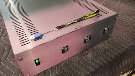
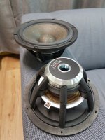
I am currently trying to convert an old AC clamp meter into an instrument usable for all audio-frequency works.

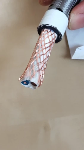
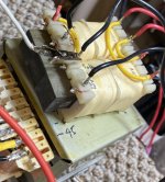
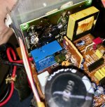
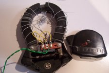
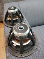
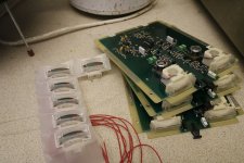
The probe in question was an "Amprobe", probably made end '60s, early '70s and was part of a graphic recorder.
It is of a poor quality standard, and does not work as a real current transformer: its magnetizing inductance acts as a large part of the shunt, and it worked and was calibrated for a single frequency, 60 or 50Hz.
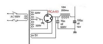
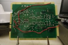
The detector used a selenium rectifier, which even at that time was already antiquated:

attachment.php


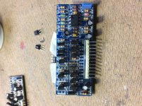
By adding a suitable electronic conditioning circuit, I hope to convert this piece of crap into something usable and accurate.

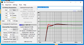
I have measured its characteristics: ~0.5H, DC resistance ~104 ohm.
Even with a perfect transimpedance input, this results in a LF cutoff >33Hz.
As I need 10x better, I have to compensate the winding resistance by a negative resistance.
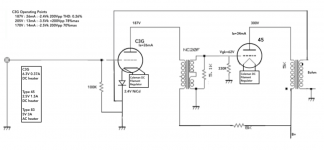
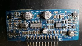
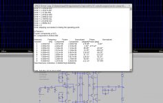
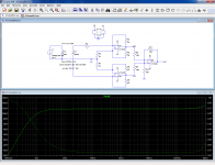
Because of the poor shielding, I have opted for a balanced circuit:

attachment.php


R1, R5 define the gain and R3, 4, 6, 7 provide the negative resistance. R4 and R7 are non-inductive copper windings, to compensate the measurement windings.
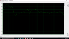
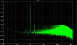
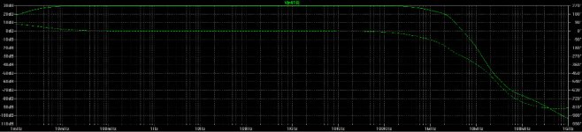
The result looks attractive, with a response flat to under 1Hz, but that is in sim only: in reality, the circuit also needs to be DC-stable, which it won't be without additional measures.
The first idea to use a blocking cap in series with the winding is not practicable; the combination of low synthetic resistance with a large inductance and capacitance results in a huge VLF resonance.

An additional pole has to be introduced somewhere, but this is no simple task: if the pole has a frequency comparable to the one already present, it will create a large peak in the response.
The pole can be placed at a much higher frequency, but this will also kill the LF capability, and placing it at a much lower frequency results results in huge time-constants and bulky components.

There is another difficulty: for noise and dynamic range reasons, the range switching should be made directly at the transimpedance stage level.
This means switching the 4 resistors, plus the possible DC-blocking caps for each range, and I intend to implement 5 ranges: from 20mA to 200A.
That is a lot of contacts.

I opted for a tradeoff: the only switching at the TIA would be the unit: mA or A. The resistors would be 60 ohm or 60K.
The 3 subranges would be created downstream, by varying the gain. The 2mA range is probably not going to be usable, but it doesn't matter.

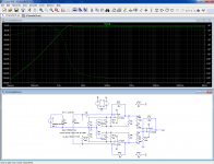
With the 60K, a capacitor would be inserted in series with the positive feedback resistor. This would still result in a DC gain >1000: awkward, but manageable:

attachment.php


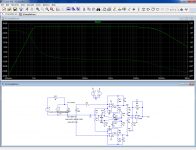
With the 60 ohm, an additional trick is needed to avoid impossibly high capacitor values:

attachment.php


All of this could be made to work, but it is complicated, clumsy and inelegant.
There must be a cleverer way to implement it, but so far I couldn't think of one.
Any creative suggestion is welcome.

The circuit is essentially a zero-field circuit (the clamp is a transformer), but with the complication of multiple ranges

Attachments

  • ACclamp1.jpg
    ACclamp1.jpg
    183.5 KB · Views: 851
  • ACclamp0.png
    ACclamp0.png
    85.9 KB · Views: 848
  • ACclamp1.png
    ACclamp1.png
    80 KB · Views: 807
  • ACclamp2.png
    ACclamp2.png
    78.8 KB · Views: 809
  • ACclampBal1b.asc
    ACclampBal1b.asc
    5 KB · Views: 109
  • ACclampBal2.asc
    ACclampBal2.asc
    6 KB · Views: 84
  • ACclampBal1.asc
    ACclampBal1.asc
    3.5 KB · Views: 81

What to do next?

Hello,

I new to working on electronics. I'm using tutorials, YouTube, and other sources to try to learn. I'm trying to resurrect a Proton D540 Amp and I'm stuck.

Here's what's up:
1. Unit powers on and lights.
2. Relay kicks in.
3. No sound.

Here's what I've done:
1. I checked both sides of the board for damaged components and broken soldered joints.
2. I replaced 2 capacitors that leaked from the bottom (capacitor plague?)
3. I've followed most of the power through the circuit
4. I've tested the resistors and capacitors around the plague
5. I've measured the transistors. Specs say order is B-C-E. Some seem reversed.Possible or bad?
5. I measure mv amounts coming through both A and B speaker connects when they are selected.
Obviously, as a newbie, I might have done any of these steps incorrectly!

What might I be missing? Thanks so much for any help!

Joel Kline

JAN6418 and microphony

I've read about how hideously microphic these tubes are, If I were to build an Oatley electronics kit (K272) would I be able to get away with the tubes being exposed through the top of the chassis? Obviously I'll have to use some type of damper with them.

My circumstances have changed and for the next couple of months at least all I am going to be able to listen to is my headphones. I need something cheap and super quick to build. I can't go far wrong with this kit can I? Anything other contenders to consider?

Rockford Fosgate T30001bd

Hey Perry I got another one T30001bd amp in. I rebuilt the powersupply and the audio board. When HV is not connected and only the ribbon cables are, I get a drive signal only on 2 of the 4 banks. Checking the signal on pin 7 of u301 and u302 they are both almost undetected or distorted. I placed a 1k ohm resistor across pin 1 & 2 of u301 and got a clean square wave. No I have drive signal on all 4 banks. I also had the correct waveforms on u400 and u401. I did power the amp the banks did not share the voltage on outputs.

Sanken MT200 transistors

As we all know by now, Sanken has discontinued ALL of their 200W and 150W MT200 transistors. We all seem to like them and are sad they are no longer in production. Now I bought numerous items from a certain reseller in Hong Kong in the past, and he ALWAYS presented me original devices... and he still sells the 2SA1216 / 2SC2922 pair. I just ordered 30 pairs, I thnk they will be original but I'll somehow test them in a test amp, put 2X 60V on it and load it with a 4 Ohms speaker. An original pair of Sankens should survive...
2SC2922 2SA1216 New Original Sanken pair, ic12.com | IC at ic12

Looking for BG RD75 substitute

My dilemma is that I started acquiring components for a line array inspired by the big Genesis 1.2's that had a version of the previously obtainable BG RD75. Have posted here and other sites looking for suggestions and have had some great suggestions. Everything from Newform research to Magnepan MMGW's.

Basic main speaker design is a stack of 4 Lab15 4ohm subs in one column for left and another stack of 4 for the right side. In a separate enclosure the plan was to be 12 Peerless 830875 Nomex cone woofers with an RD75 in a separate chamber. 4 Fountek Neo CD 2.0 Ribbons will act as super tweeters.

Subs, Woofers and Fountek's already acquired. System is active with DBX260 for management.

One new option which I thought of myself is a stack of 9 Dayton AMTPro4's Dayton Audio AMTPRO-4 Air Motion Transformer Tweeter 4 Ohm per side. These would easily meet SPL requirements, stack 71" high to maintain line array attributes. Individually they are well reviewed. While they do not go as low as the RD75's 250hz it seems that they can do 800hz which should work quite well with the Peerless woofers. This would absolutely push my budget to the limit since our Canadian dollar has tanked. We are talking $3500 for 18 of these to my door. 2 X RD75's with current exchange and tax would have been $2400.

Open to suggestions, alternate drivers etc.

Cheers
Derek

Sovtek Heaters

I wanted to run my 6SN7GT tubes off of constant current sources or constant voltage sources. So I built 2 circuits using LM317's to see what happens.
The circuits are for running just one tube by it's self.

Constant Current:
Sovtek-1 6SN7GT 5.552vdc at 600ma. (3.33w)
Sovtek-2 6SN7GT 5.573vdc at 600ma. (3.34w)
Sovtek-3 6SN7GT 5.632vdc at 600ma. (3.37w)
Raytheon 6SN7GT 6.344vdc at 600ma. (3.8w)

Constant Voltage:
Sovtek-1 6SNTGT 6.306vdc at 650ma (4.09w)
Sovtek-2 6SN7GT 6.305vdc at 650ma. (4.09w)
Sovtek-3 6SN7GT 6.304vdc at 640ma. (4.03w)
Raytheon 6SN7GT 6.300vdc at 600ma. (3.78w)

Sovtek-1 was purchased in the 90's the other 2 in the last couple of weeks.
Sovtek specs for the heaters: 6.9v max to 5.7v min with the current being 600ma +60ma or -50ma.

So I am undervolting using a constant current source on the Sovtek tubes.
It seems to me that these Sovtek tubes need to be run in constant voltage only or you will under power them.

Sovtek data sheets always reference to 6.3 so I'm thinking constant voltage without trimming to 3.78 watts is the way to go..

Any suggestions on what to do in a situation like this..?

Calculating PT / Basics

Hello Everyone,


I have built a few Tubeamps so far. Out of 7 Amps 6 worked right away and one i had to Bugfix a minor mistake i made. Now i would dare to say a have a small Idea how TubeAmps work. But now i would like to have a bit deeper knowledge. Soooo.... I have a Amp Kit here with a Preamp stage of an EF86 and a ECC83 and the Amp Stage consists of two EL84 in PP mode. The Amp is Rectified by an EZ81 and i have a PT with sec: 300V(100mA), 8V(2A), 6.3V(3.2A) and 6,3V(2A)


So, i have 100mA to work with the Tubes. I start to calculate:


EF86 (Ia = 3,0mA)
ECC83 (Ia = 1,2mA)

EL84 (Ia = 48mA)


a Total of 100.2 mA needed.


My Question:

I assume now, a PT shall NOT have more than the 100mA ? (because it would burn the tubes?) but as close as possible?

I am aware of the Condensators and Resistors in the Schematics but they are irrelevant for Ia (not for the voltage of course)
Or is my way of thinking complete wrong?


Thanks for Helping a Newbie
Pero

Medium cost 3-way, midbass driver vented or closed ? Walls parallel ?

Dear all,

without striving for perfect high-end sound I decided to build a 3-way stereo to the kitchen / living room, to the sides of the tv so we can use it for music and movies as well (in 2.0 but it's okay).

l'm going to put all drivers into separate boxes.

My question regards the Faital 6FE100 midbass/midrange driver.

I modeled in WinISD both boxed and vented versions, pretty much the same results with negligible deviations.

1. Which variant would you use ? Vented or boxed ? According to Qts the recommendation rather closed, according to EBP it's rather vented. I assume I'd be fine with closed for a more precise sound, or am I wrong ? Which way would you go ? Or maybe try closed first and if it doesn't work out that well, drill the box ? 🙂

2. 1st XO freq. intended to be 70 or 80Hz, electronic active 3-way, 4th order LR. (Aiming for side mounted woofer(s)).

3. With a 48 liters box.. both vented (tuned to fs) and closed box variants are okay. An ideal volume and size too, for this driver.

4. I bought the wooden sheets for the boxes. Would you stay at a classic design with parallel walls, or does it make ANY sense to make the 2 bigger walls non-parallel to eachother ? A small amount of angle I can cut from the wood, but I'm not sure if it brings that much benefit to avoid standing waves. A somewhat bigger angle I don't want to do, then I rather stay with a classic design. Simpler anyway.


Any opinions ? Thank you !

Dolby stereo CP200 in my home THX cinema

I been after one of these for years as an ex projectionist its a classic cinema processor.

Attachments

  • 67782258_10157287141145149_2406165405069475840_o.jpg
    67782258_10157287141145149_2406165405069475840_o.jpg
    83.4 KB · Views: 298
  • 67941115_10157287141655149_2925406593010892800_o.jpg
    67941115_10157287141655149_2925406593010892800_o.jpg
    89.1 KB · Views: 280
  • 67802809_10157287141475149_3485996272924491776_o.jpg
    67802809_10157287141475149_3485996272924491776_o.jpg
    72.6 KB · Views: 243
  • 69218134_10157331015830149_8765243371632459776_o.jpg
    69218134_10157331015830149_8765243371632459776_o.jpg
    51.8 KB · Views: 337
  • 67909816_10157303268035149_7541509143488626688_o.jpg
    67909816_10157303268035149_7541509143488626688_o.jpg
    104 KB · Views: 240
  • 69155451_10157306374610149_1331810075056013312_o.jpg
    69155451_10157306374610149_1331810075056013312_o.jpg
    77.9 KB · Views: 246
  • 67952024_10157306377660149_1123520817083187200_o (1).jpg
    67952024_10157306377660149_1123520817083187200_o (1).jpg
    80.5 KB · Views: 188
  • 80486418_10157648375150149_8672099798863577088_o.jpg
    80486418_10157648375150149_8672099798863577088_o.jpg
    14.9 KB · Views: 213
  • 67918550_10157287142455149_7394640920030740480_o.jpg
    67918550_10157287142455149_7394640920030740480_o.jpg
    102.3 KB · Views: 194
  • 82024082_10157716732190149_8123197450811867136_o.jpg
    82024082_10157716732190149_8123197450811867136_o.jpg
    91.9 KB · Views: 225

How to Configure a 7.1 PC Soundcard as an Active Stereo Crossover?

How to Configure a PC Soundcard as an Active Stereo Crossover?

Could the Asus STX II 7.1 sound card be used as an active crossover for driving a stereo 3 way speaker system with 3 stereo amplifiers?

My question is, is there a way to configure this card to work as a high fidelity Digital to Analog crossover that outputs 6 channels like this:

LL: Low Left (20 - 300 Hz) ---__ Rear Left RCA
LR: Low Right (20 - 300 Hz) ---__ Rear Right RCA

ML: Mid Left (300 Hz - 3Khz) __---__ Front Left RCA
MR: Mid Right (300 Hz - 3Khz) __---__ Front Right RCA

HL: High Left (3Khz - 20Khz) __--- Side Left RCA
HR: High Right (3Khz - 20 Khz) __--- Side Left RCA

If such a thing would be possible, then the Digital signal from the computer needs to be converted only once to analog via this 7.1 soundcard, and the three pairs (Low, Mid and High) could each go to three identical amplifiers after which the signales can go directly to the speakers, bypassing the analogue crossovers entirely.

In theorie this should be possible, with software.

But is it actually possible in reality??

- If not, then why not? Prove why its not possible.
- If yess, then in what way(s) you think it could/might?
- If you have any ideas or suggestions or tips, you are most welcome to share!

asus-xonar-essence-stx-ii-71.jpg


asus-xonar-essence-stx-ii-71.jpg


asus-xonar-essence-stx-ii-71.jpg


asus-xonar-essence-stx-ii-71.jpg


NzJmYjM4Zjk1ZTVkZjgwZDY2MGY2M2E0NWZhMmE1ZjK5-lyQ08qwtY5iMp00VwmLaHR0cDovL21lZGlhLmFkc2ltZy5jb20vZjc2YWY4MDI0NDZmY2QzMWY5OWMzYjA4ZjYwMWRjZGMwOTM3YWNhNmNiYjcxZjEyNjZkMTUwN2I0OWI1NTRiNS5qcGd8fHx8fHw3MDB4Mjg3fGh0dHA6Ly93d3cuYWR2ZXJ0cy5pZS9zdGF0aWMvaS93YXRlcm1hcmsucG5nfHx8.jpg


24bc18cb21c38604824f5821c073b6eb.jpg


gasc-082_gasc_082_8g_800x800.jpg
Projects by fanatics, for fanatics
Get answers and advice for everyone wanting to learn the art of audio.
Join the Community
508,474
Members
7,921,268
Messages

Filter

Forum Statistics

Threads
407,846
Messages
7,921,268
Members
508,474
Latest member
cuong nguyen