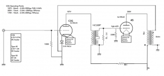
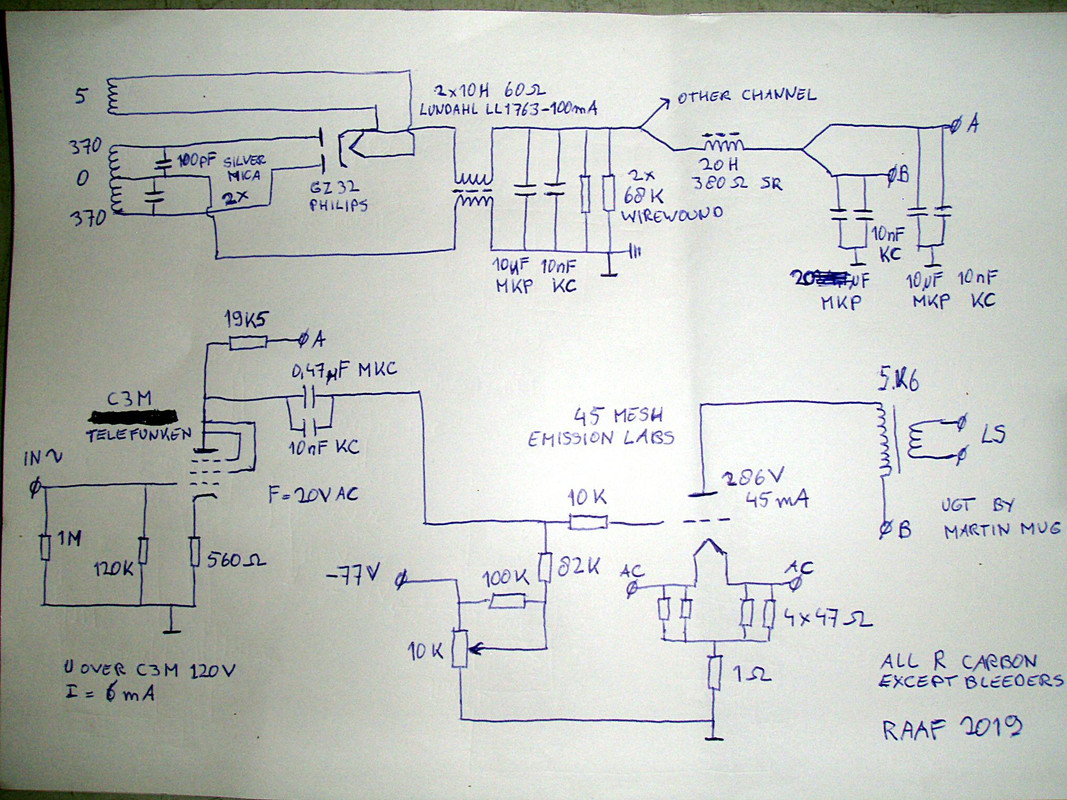
Hello. I am building C3G --> IT --> 45 monoblocks. The attached schematics are mostly cut/paste from others. I do have a few questions and would appreciate your review of the schematic. This amp is intended to be a minimalist approach using a solid design and high quality parts.
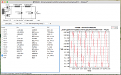
1. I used PSUD for the power supply and am getting about 52mV ripple which should result in about 2mV ripple at after the output transformer. Any suggestions on the power supply? The CLC design is simple, but I need to know if it is sufficient or should I go with an LCLC?
2. The operating points are from bartola's excellent web site. I don't have the know-how to challenge those operating points, so any input would be appreciated.
3. Rod Coleman DC filament regulators will be used with a 330ohm grid bias resistor on the 45. Is the 330 ohm resistor in the correct place (grid leak) or should it be in the grid stopper position.
Any and all input is welcome.
Attachments
The 330 ohm resistor should not be there.
The connection from the top of the secondary back to the cathode of the driver tube should not be there.
There is no biasing method employed here for the 45.
Is 52mV of ripple peak-to-peak or RMS? Is that at the 100uF cap or elsewhere in PSUD?
There should be a cap to ground after the 8K resistor.
For a minimalist approach, ditch the interstage transformer!
The 330 ohm resistor should not be there.
The connection from the top of the secondary back to the cathode of the driver tube should not be there.
There is no biasing method employed here for the 45.
Is 52mV of ripple peak-to-peak or RMS? Is that at the 100uF cap or elsewhere in PSUD?
There should be a cap to ground after the 8K resistor.
For a minimalist approach, ditch the interstage transformer!
audiowize thanks for helping. A couple of follow up comments / questions.
1. The 52mV of ripple is p2p measured at the 100uF cap.
2. The intent of the 330 ohm resistor was to create griD bias for the 45 tube. I am going with grid bias to avoid the Signal having to go thru a cathode bias cap. Thoughts?
3. I understand your other points and will adjust the schematic accordingly
banpuku,
Where did you get these schematics?
They have major errors.
Or, who modified the schematics?
And, the 2 schematics will not work together; they are not made for each other, the voltages do not match.
1. Perhaps the 330R was supposed to be in series from the interstage output to the 45 grid.
(grid stopper, and grid current limiter, all in one).
2. Your 8 Ohm output tap comes back to the ground of C3G cathode circuit.
That is a dead short!
3. The diode in the C3G cathode circuit is not a NiCad battery.
What NiCad battery (how many cells in series)?
Or, what diode, how many in series?
Or, is the diode a Zener, how many volts?
4. Where is the self bias resistor from the 45's Coleman Regulator to ground?
No path to ground through a self bias resistor, then no plate current, then not working.
5. The power supply B+ secondary is 320V, that is 452.5V peak. The 83 rectifier drop is 15V.
452.5V - 15V = 437.5V.
Wow!
The 45 maximum plate to filament voltage is 275V. The bias could be as high as 56V.
275V + 56V = 331V.
But, you have 437.5V B+.
437.5V - 331V = 106.5V excessive B+.
The 45 will die.
6. Danger! 83 may explode! Possible Mercury Poisoning!
The 83 rectifier is supposed to work into a Choke input B+ filter.
You are using a Cap input filter, that could make it explode.
Mercury everywhere!
The B+ filter needs to be Choke, Cap, resistor, Cap.
It must NOT be Cap, Choke, Cap.
6. (part 2) And . . . the 83 and required choke input filter, B+ will be:
320V x 0.9 volts to the rectifier = 288V
288V - 15V = 273V.
Wow, that is Very close to 275V B+, Good!
A. You can use fixed adjustable bias (range about -50v to -65V, and apply the bias voltage to the bottom connection of the interstage transformer secondary.
B. Or, you can still use self bias for the 45, and it will last longer.
The 45 needs bias, and self bias resistor in the filament/Coleman regulator circuit to ground takes care of the bias issue. Be sure to bypass the self bias resistor with a bypass capacitor.
Hopefully, you will soon get things right.
Last edited:
banpuku,
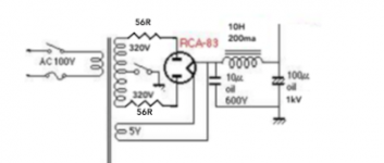
If you still want to use an 83 rectifier, and Cap input B+ filter,
then you will need to use a 56 Ohm resistor in series with each plate two 56 Ohm resistors).
But the B+ will still be too much for the 45.
So use the 56 Ohm series resistors from the B+ power transformer secondary leads to the 83 plates.
And then use a 0.27uF first filter cap (600V rating), instead of the 10uF cap.
That will lower the B+ voltage to about 326.4V.
275V across the 45 + 56V self bias = 331V.
That will work great with a 1500 Ohm self bias resistor on the 45.
Make the other fixes to the amp and you will be up and listening all night long.
That's 18mV RMS. Consider running that through your calculations. Generally anything under 1mV at the speaker posts for a zero feedback tube power amp is OK.1. The 52mV of ripple is p2p measured at the 100uF cap.
Well, the signal in this amp is already going through two caps. If you want to bias the tube with fixed bias, you would need to apply negative voltage to the output winding of the interstage transformer. That will add another cap in the signal path. Such is life.2. The intent of the 330 ohm resistor was to create griD bias for the 45 tube. I am going with grid bias to avoid the Signal having to go thru a cathode bias cap. Thoughts?
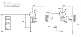
Everyone, thanks for the help so far. The attached schematics reflect the following changes:
1. removed the intended fixed bias resistor of 300R and replaced with a self bias network 1500R + cap. As you will see, I do not know what value the cap should be (see blue highlight on schematic). Please let me know how to determine this value. It is my understanding that this cap will be in the signal path, and thus I want to use a high quality audio cap (read, no electrolytics).
2. Add the 100uF cap after then 8k resistor between B+ and Interstage tranny.
3. clarified the use of a 2.4V LED for bias on the driver tube (C3G).
4. Added 2 x 56R 10W resistors to bring B+ down.
5. 6A3sUMMER, you suggested changing the first cap in the power supply from 10uF to 0.27uF. I did this within PSUD and the B+ ripple went up from 54mV to ~450mV. I might not be modeling this correctly in PSUD, but not sure a ~450mV ripple is what we want. Thoughts? Help educate me here, please.
OK, progress. More comments / scrutiny please!!!
Attachments
The cap can be 47uF-100uF, that should be OK.
The Coleman DC heater on the C3G is overkill and not necessary. If you have a 6.3V winding that's rated for at least 1A, you can make a bridge with 1N5818 diodes, feed that to a .47 ohm resistor (may need to be 0.47-1.5 ohms depending a little on the winding itself), then feed that to a 10,000uF/10V cap and make yourself a DC heater supply that should work well for the job. This set of components would be required to feed the Coleman regulator anyway, so it's not like you're adding parts.
As far as the power supply goes, a high voltage winding with less voltage is the way to go.
-PB
Last edited:
The 330 ohm resistor should not be there.
The connection from the top of the secondary back to the cathode of the driver tube should not be there.
There should be a cap to ground after the 8K resistor.
For a minimalist approach, ditch the interstage transformer!
Direct coupling jumped out at me too.
The 83 pi supply is a fantastic choice.
The Coleman DC heater on the C3G is overkill and not necessary.
-PB
My power transformer has 6.3Vac secondary. What do you think about running 6.3V AC directly from the power transformer secondary to the C3G filaments? Use Coleman DC only on the 45 output tube.
6. Danger! 83 may explode! Possible Mercury Poisoning!
The 83 rectifier is supposed to work into a Choke input B+ filter.
You are using a Cap input filter, that could make it explode.
Mercury everywhere!
The B+ filter needs to be Choke, Cap, resistor, Cap.
It must NOT be Cap, Choke, Cap.
6. (part 2) And . . . the 83 and required choke input filter, B+ will be:
320V x 0.9 volts to the rectifier = 288V
288V - 15V = 273V.
Wow, that is Very close to 275V B+, Good!
These datasheets of the 83 indicate that capacitor input filters are allowed:
https://frank.pocnet.net/sheets/021/8/83.pdf
https://frank.pocnet.net/sheets/049/8/83.pdf
https://frank.pocnet.net/sheets/093/8/83.pdf
Looking at the curves in the last datasheet, i think that the two upper curves are for a capacitor input filter (C = 4 uF), while the lower curves are for a choke input (C = 0 uF). Two 45's will draw about 90 mA. Than it is more likely that the output voltage with a choke input filter will be about 240 V instead of about 273 V.
Hi
Ok, c3g running 45 is something I am familiar with.
1. Running the C3g at 26mA with nominal 187V on the plate will kill it much faster and will be a real pity. These tubes run at a max Q of 3.5 Watts. You are running pentode, right? What is G2 at? Look at the Siemens Datasheet please. Do not kill such a beautiful tube/valve.
2. If you are running C3g in pentode, why do this? Serious.. C3g is much better triode strapped. If you need more swing, go for C3m in Pentode (different heater volts though).
2a. Your interstage likes 30mA, and you need to re-consider running your C3g so hot, and it is already at 26mA (too much imho). Why not go for a different tube than C3g then? C3m could do it, since you have a loctal socket, but hey, I can think of a few other great pentodes besides that. Or go for D3a, etc.
3. Sorry, your power supply is just not going to be so great. Lots of problems with it I see. A quick fix would be to use a Big Motor Run cap on the input. But seriously, Choke input will be much better anyway. Want to get the ripple down? Use a second filter choke.")
4. I think running 45's at 300V on the plate is criminal. You need to get that B+ down anyway.. to get the C3g's down to somewhere cooler. I like 260V on the plate for 45's.
So why not take out the 10uF cap input and make it choke input supply instead? If your choke does not buzz then it should be OK. If it buzzes, then you need to get a better input choke... or maybe only use a much smaller input cap...
You need to re-juggle the math to make sure it all works. Your cathode bypass cap will probably need to be 50uF or more, depending on the value of your cathode resistor.
Don't do direct coupling unless you really really know what you are doing.
Ok, c3g running 45 is something I am familiar with.
1. Running the C3g at 26mA with nominal 187V on the plate will kill it much faster and will be a real pity. These tubes run at a max Q of 3.5 Watts. You are running pentode, right? What is G2 at? Look at the Siemens Datasheet please. Do not kill such a beautiful tube/valve.
2. If you are running C3g in pentode, why do this? Serious.. C3g is much better triode strapped. If you need more swing, go for C3m in Pentode (different heater volts though).
2a. Your interstage likes 30mA, and you need to re-consider running your C3g so hot, and it is already at 26mA (too much imho). Why not go for a different tube than C3g then? C3m could do it, since you have a loctal socket, but hey, I can think of a few other great pentodes besides that. Or go for D3a, etc.
3. Sorry, your power supply is just not going to be so great. Lots of problems with it I see. A quick fix would be to use a Big Motor Run cap on the input. But seriously, Choke input will be much better anyway. Want to get the ripple down? Use a second filter choke.
4. I think running 45's at 300V on the plate is criminal. You need to get that B+ down anyway.. to get the C3g's down to somewhere cooler. I like 260V on the plate for 45's.
So why not take out the 10uF cap input and make it choke input supply instead? If your choke does not buzz then it should be OK. If it buzzes, then you need to get a better input choke... or maybe only use a much smaller input cap...
You need to re-juggle the math to make sure it all works. Your cathode bypass cap will probably need to be 50uF or more, depending on the value of your cathode resistor.
Don't do direct coupling unless you really really know what you are doing.
Last edited:
Two 45's will draw about 90 mA. Than it is more likely that the output voltage with a choke input filter will be about 240 V instead of about 273 V.
Sorry for the confusion: These are monoblock schematics, so the power supply is for 1 x 45 tube and 1 x C3G and 1 x 83 rectifier.
My power transformer has 6.3Vac secondary. What do you think about running 6.3V AC directly from the power transformer secondary to the C3G filaments? Use Coleman DC only on the 45 output tube.
You can certainly try this.
Hi
Ok, c3g running 45 is something I am familiar with.
2. If you are running C3g in pentode, why do this?
2a. Your interstage likes 30mA, and you need to re-consider running your C3g so hot, and it is already at 26mA (too much imho). Why not go for a different tube than C3g then? C3m could do it, since you have a loctal socket, but hey, I can think of a few other great pentodes besides that.
3. Sorry, your power supply is just not going to be so great. Lots of problems with it I see. A quick fix would be to use a Big Motor Run cap on the input. But seriously, Choke input will be much better anyway. Want to get the ripple down? Use a second filter choke.
4. I think running 45's at 300V on the plate is criminal. You need to get that B+ down anyway.. to get the C3g's down to somewhere cooler. I like 260V on the plate for 45's.
Don't do direct coupling unless you really really know what you are doing.
Thanks for the detailed feedback, soulmerchant. Here are my thoughts:
1. Intent is to run C3G in triode mode, not pentode. Please share you have ideas for better drivers tubes (loctal, 8-pin, 9-pin or UX4, as I have all of these sockets and have not purchased the driver tubes yet).
2. Please see attache LCLC power supply PSUD. This is certainly an option. P2P B+ ripple is 25mV. Output would be 252Vdc without using any resistors prior to the LCLC. Other DIYers like the CLC pi power supply. Thoughts on one over the other?
Do you have C3G --> 45 schematic you can share?
Thanks
Attachments
Cost.Other DIYers like the CLC pi power supply. Thoughts on one over the other?
Capacitors are cheap today. And the choke for the choke-input filter should be BIG. I mean, something of the size of 40-50W power transformer in your case.
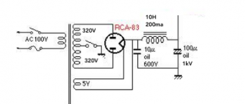
Do you have C3G --> 45 schematic you can share?
Thanks
In this schematic the 45 has AC heating but I Use a DC regulator now .
Do you have C3G --> 45 schematic you can share?
Attachments
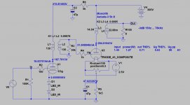
Thank you very much for sharing. Your design has a 1K grid stopper for the Output Tube and a 30K across the interstage transformer. I was reading from Thomas Mayer's site that he prefers to run the interstage transformers unloaded whenever possible. He runs the IT directly into the plate of the output tube (no resistors). Curious if you have tried running the ITs without the 30K or 1K resistors?
Also, are the 30K and 1K resistors necessary or an alternative approach whereby either design is valid?
- Status
- This old topic is closed. If you want to reopen this topic, contact a moderator using the "Report Post" button.
- Home
- Amplifiers
- Tubes / Valves
- C3G drives 45