If you have 2 each C3g tubes that use LED (constant voltage) biasing . . .
then please, do not expect the tube voltages / currents to be the same.
Live with the different voltages / currents, Or . . .
Find better matched C3g tubes (real expensive);
Use a current sink to bias the C3g (and put a bypass cap across the current sink);
Or (real scary to some), use a self bias resistor with a bypass cap across it.
There are reasons why some designers use something different than LED biasing.
But your results are well within normal tube variations, stop worrying about it.
I would suggest that the slight difference of plate voltage and slight difference of plate current is lots less than most peoples 2 ears
(have you had a complete ear test lately, and compared the difference between the Left and Right ear sensitivity and frequency response).
Last edited:
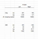
voltage across the RC 10K resistor is approx: 200V and 190V. I ordered some new 10K power resistors (25W) and will install in 2 days.
I was using battery bias (-2.7V) and am going to go back to the LED bias shortly. FYI: with the measurements posted earlier today, the output voltage for a 120hz -12db sine wave is 2.2V and 2.4V (left and right monoblocks, respectively). So, about a 10% voltage difference at the OPT output.
I was using battery bias (-2.7V) and am going to go back to the LED bias shortly. FYI: with the measurements posted earlier today, the output voltage for a 120hz -12db sine wave is 2.2V and 2.4V (left and right monoblocks, respectively). So, about a 10% voltage difference at the OPT output.
Last edited by a moderator:
That is a 1dB difference.
Check your phono cartridges alignment and channel balance, check your phono preamp channels gain balance, check the balance of your speakers in your room, . . .
and then worry about a 1 dB amplifier balance problem (by the way, the output tubes gains may or may not be balanced too, swap the 45B tubes and see if there is still a 1dB difference).
Once all that is done, check the balance of all your recordings.
voltage across the RC 10K resistor is approx: 200V and 190V. I ordered some new 10K power resistors (25W) and will install in 2 days.
I was using battery bias (-2.7V) and am going to go back to the LED bias shortly. FYI: with the measurements posted earlier today, the output voltage for a 120hz -12db sine wave is 2.2V and 2.4V (left and right monoblocks, respectively). So, about a 10% voltage difference at the OPT output.
There is nothing wrong with the resistors. Ohms law will tell you one tube is drawing more current than the other. 6A3sUMMER is correct with his assessment of the led bias. The c3g tubes are not matched and bias differently with the same grid voltage.
If you have 2 each C3g tubes that use LED (constant voltage) biasing . . .
then please, do not expect the tube voltages / currents to be the same.
Live with the different voltages / currents, Or . . .
Find better matched C3g tubes (real expensive);
Use a current sink to bias the C3g (and put a bypass cap across the current sink);
Or (real scary to some), use a self bias resistor with a bypass cap across it.
There are reasons why some designers use something different than LED biasing.
But your results are well within normal tube variations, stop worrying about it.
I would suggest that the slight difference of plate voltage and slight difference of plate current is lots less than most peoples 2 ears
(have you had a complete ear test lately, and compared the difference between the Left and Right ear sensitivity and frequency response).
I just use a resistor. 😉
A few follow-up questions:
1. Instead of using an LED to bias the C3g, could I use a resistor without a bypass capacitor? Also, is the music signal going thru the bias resistor? Please confirm my thinking on the resistor size: Voltage drop = 3V. Amps = 17mA. R = 3 / .017 = 176 ohms.
2. Why is a 100ohm resistor needed across G2 to Anode in order for the C3g to run in triode mode? What is the benefit?
Fine tuning time:
To set the stage with my gear, for this round of listening, I am using digital only. Speakers are 90db efficient. I am using a EMIA Elmaformer (FYI: This is a great piece of audio equipment) as passive volume control which is being fed by a Auris Blume DAC (2.1V RMS output, 57ohm output impedance). The monoblocks have a 47k input resistor.
Existing measurements / operating points attached.
The sound: The amps have been running on and off for about 70-80 hours. They start to really open up after a few hours of being turned on. Tonality is spot on for my liking. Perfect, if you will, for my taste in classical chamber music. Very silky and extended highs without any hint electronic artifact. Bass is extended and full, but not as punchy as I would prefer. Dynamics are good, not great. Harmonics seem just right. Not too rich but not too thin. Seems lifelike to me. Soundstage depth is improving as the amps break in.
What would like to improve: dynamic punch, firmer bass and more air around the instruments. I am not sure what to change to help improve these areas. I don't want to give up any output power, if I don't have too. Thoughts?
Attachments
banpuku,
1. You want Bass Punch?
Check the following:
What is the plate resistance, rp, of the C3g in triode mode?
What is the primary inductance of the interstage transformer?
What is the resultant -3dB low frequency bandwidth of that stage?
The -1dB bandwidth will be 1 Octave higher than that.
What is the primary inductance of the output transformer.
What is the plate resistance, rp, of the 45B?
What is the resultant -3dB low frequency bandwidth of that stage?
The -1dB bandwidth will be 1 Octave higher than that.
Suppose both of those stages are each -3dB at 40Hz, then the amp will be
-6dB at 40Hz.
Suppose both of those stages are each -1.5dB at 40 Hz, then the amp will be
-3dB at 40Hz.
Do some calculations. Find out what stage or stages are the low frequency limiting factor.
What is the damping factor of the amplifier. Measure it.
It is not just simply 5000 Ohms / rp of the 45B.
That is because the output transformer has losses from the DCR of the primary, and the DCR of the secondary. Those reduce the damping factor.
Consider amplifiers that do not have local negative feedback, and that do not have global negative feedback:
Finally, do you have "woofer walk" syndrome?
With single ended amplifiers, the damping factor is not the same in the positive polarity as in the negative polarity. That can cause the woofer to "walk" (the woofer builds up a mechanical offset during a bass note).
A push pull triode amplifier has equal damping factor in the positive polarity and the negative polarity.
Single Ended amplifiers have many advantages.
Push Pull amplifiers have many advantages.
Now you know one of the differences, amplifier causes woofer walk, or does not cause woofer walk.
And as a general rule, without global negative feedback, the single ended amplifier has more 2nd harmonic than a push pull amplifier.
That changes the Timbre (and likely the "Punch" of the bass line).
"All Generalizations Have Exceptions" - Me
2. You want more Air around the instruments?
You picked a real tough question, especially since your amplifier seems to have pedigree topology and parts.
What is your room like?
How do you have the speakers located in that room?
Are you listening near field, or do you have more room reflections?
What loudspeakers do you have?
What is your signal source, and what recordings are you listening to?
Do you have another amplifier that you have heard in your system to compare it to the 45B amplifier?
Otherwise, more Air compared to what? Someone else's system?
it just might be time to be satisfied for now.
Relax, enjoy the music.
Last edited:
more caps in psu , a low R coke ...just test with plain resistor , a new load/op for 45 ? maybe
Team - many thanks to those who have helped along the way. I am very very pleased with the performance of the C3g --> EML 45B. Here are the operating points:
C3g
200V, 20mA, -3.3V battery bias
45B
410V, 60mA, -58V UltraPath bias
The 45B cathode bias is using UltraPath. I did some A/B testing and found the UltraPath preferable to the typical RC schema.
Hum: 4mV which is undetectable with my 90db speakers.
So, as we think about version 2, what enhancements would you recommend? I am in no hurry, but its fun to dream.
Thanks again to everyone who helped! I learned so much.
Pat
I have adjusted the C3g operating points as follows: 186V, 13.5mA and -2.1 bias.
The 45B operating points that I posted earlier were incorrect, as the resistor going to the ammeter had an incorrect value. Here is the existing 45B operating points: 395V, 45mA and -62 bias.
I may try to up the voltage of the C3g to 200V with 15mA. More to come.
The 45B operating points that I posted earlier were incorrect, as the resistor going to the ammeter had an incorrect value. Here is the existing 45B operating points: 395V, 45mA and -62 bias.
I may try to up the voltage of the C3g to 200V with 15mA. More to come.
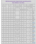
Please see load lines & operating points in the attached file. The yellow operating points are a result of Rk=1k. The blue operating points are Rk=1.5k. B+ = 398V.
I am unsure which is "better", as load lines and operating points are new to me. Both operating points appear to be moved to the "right" of the chart. Am I correct that the operating point should be roughly centered between the 0.0 bias and -100 bias?
To confuse me further, the EML website has operating points suggested in the response above from nicoch58.
Attachments
- Home
- Amplifiers
- Tubes / Valves
- C3G drives 45