A little cap at the rectifier→L1 node is worth having.
470n or 680nF 1.5kV DC rated, MKP - for example.
470n or 680nF 1.5kV DC rated, MKP - for example.
A little cap at the rectifier→L1 node is worth having.
470n or 680nF 1.5kV DC rated, MKP - for example.
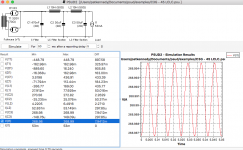
Does this look right?
Ripple increased slightly. What is the benefit / purpose of this little cap?
Attachments
Team - I also have a pair of custom made, J&K 100H chokes. Not sure if they would be usable in this amp, or not. Otherwise, I may sell them. Thoughts?
You got more ripple because you changed the cap that was between the two 10H chokes . . .
from 50uF to 30uF.
I think the small cap was to reduce any transient and/or high frequency noise.
It should not change the final ripple significantly.
from 50uF to 30uF.
I think the small cap was to reduce any transient and/or high frequency noise.
It should not change the final ripple significantly.
So, I am trying to get a subjective feel for what 2-4 watts of power will sound like on 45B amp we are designing. So, I turned on some music with an existing amp on my 90db efficient speakers which nominal impedance of 8 ohms. At normal listening levels, the Vac at the speaker terminals peaked at 1.4 Vac. most of the time it loafed along at 0.1 to 0.3 Vac.
Let's use the peak of 1.4 Vac. P = V*V/R = 1.4 * 1.4 / 8 = 0.245 watts.
Also, I read where 2.83Vac = 1 Watt for 8 ohm load. This confirms my math.
Am I missing something? Otherwise, the 2-4 watts that will come from the 45B should produce more than expected output in my near listening room position (8' from speakers).
A real 45 tube is not going to put out 4 watts rms to the speaker, unless it is clipping very badly (a square wave does not sound like music).
A real 45 with 275 Vplate to filament, 36mA, 4600 Ohm load, gets 2 Watts, maybe a little less depending on the output transformer insertion loss.
How are you measuring the 1.4Vac?
With a digital scope set to rms volts?
Into an 8 Ohm resistor?
An 8 Ohm rated loudspeaker may have impedance versus frequency that is as low as 4 Ohms or less, and as high as 20 or 40 Ohms or more.
Set the amplifier gain for a known voltage into an 8 Ohm resistor, and then connect it to the loudspeaker.
A scope display with a 2.828 Vrms sine wave will have 4V at the positive crest, and -4V at the negative crest (8V peak to peak).
That is 1 Watt into an 8 Ohm resistor.
Outside, (with no walls), the difference in sound power at 8 feet is only 1/4 of the sound power at 4 feet.
Sound drops off at the square of the distance.
Of course, a room with walls gives reflections, which reduces the power drop off rate somewhat.
And, yes, some people are surprised by how loud 1 watt sounds on a moderate efficiency loudspeaker.
Last edited:
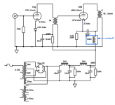
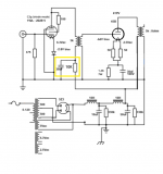
Here is the most recent version. Notice the changes as follows:
1. an ultrapath cap on the 45 tube
2. addition of a 100H choke (I have a pair of spare J&K 100H chokes and would like to use them). My understanding is that the ultrapath bias will work as long as B+ is well filtered. The power supply is LCLC and the 100H choke was added for extra filtering
3. larger power supply to drive the 45B tube into higher output power
What do you think?
Attachments
Wrong.
The 100H anode choke must connect to anode (choke loaded tube).
The parafeed capacitor (which is missing) and the series transformer primary wiring across anode and cathode.
The ultrapath cap connecting to B+.
The 100H anode choke must connect to anode (choke loaded tube).
The parafeed capacitor (which is missing) and the series transformer primary wiring across anode and cathode.
The ultrapath cap connecting to B+.
Last edited:
Wrong.
The 100H anode choke must connect to anode (choke loaded tube).
The parafeed capacitor (which is missing) and the series transformer primary wiring across anode and cathode.
The ultrapath cap connecting to B+.
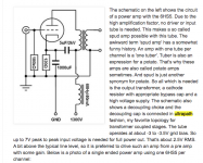
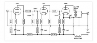
Please see the attached schematics below from Thomas Mayers site. He uses Ultrapath and I believe my schematic mimics his schematics. My 100H choke is a decoupling choke. My ultrapath cap is connected to B+. Unless I am missing something, my schematic looks OK.
Attachments
Using costly 100H plate choke as power supply choke is not an average solution.
In this case it is unnecessary, the previous LC tages has enough filtrating capacity.
IMHO in this case ultrapath also unnecessary, just another technical solution, not better than using without it.
BTW is your schematic missing the B+ decoupling capacitor (after 100H choke).
If you have decent 100H anode choke, the parafeed connection IMHO is better (not stressed OPT with large anode current).
Last edited:
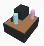
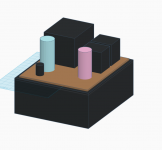
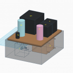
OK team - time to chime in about the layout of the parts within chassis. There are 2 alternatives under consideration. The first has L1 and L2 on top of the chassis. The 2nd has L1 and L2 in the chassis. My concern is about EMI from L1 and the 83 rectifier. The outside dimensions of the chassis is 14L x 12W x 6H (inches). All of the iron is shielded, potted and encased within steel cases. So, should I worry about the proximity of L1 and 83 rectifier in relation to the input/output stage? Your thoughts?
Pat
Pat
Attachments

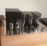
Progress, sort of. The first monoblock has been assembled. PT is 500-0-500. Measuring 500Vac, spot on. Then, the 83 rectifier: 638Vdc measured from filament pin to ground. This seems very high. Note, these measurements are without the driver nor output tube installed. Thoughts?
Hi, sorry I have not been online here much.
Some thoughts:
1. work out the schematic first. Think very carefully about layout after.
2. Think about breadboarding the amplifier before building it in a chassis. Transformer layout needs consideration.
3. Do you have a variac? I always bring up a new build slowly. and measure... But hey, its your stuff, money, whatever. I think everyone here has had some kind of experience... I blew a few electrolytic caps that were wired wrong years ago. they made a super loud POP sound when they blew. Fun? not really... I learned to be much more careful.
4. See point #1.
Ok, so you power up the transformer and have zero load and your voltage goes up very high? What did you expect? There is no load.
Try it in PSU II without load and see what you get.
Hope your caps have by-pass resistors, and they can take that 638VDC voltage (!) or else they might burn and crack... a 100k Ohm resistor will need to dissipate over 4 Watts at that voltage, right?
If your caps do not have a by-pass resistor... well, that is dangerous.
I used a gyrator load and have done it with 2a3 as well as 45 and 46 tubes/valves. And I do AC heaters and no, there is no audible hum on 98db speakers
My Gyrators are super stable. No real need for any adjustments since early 2017 in the 2a3 amp. I guess a plate choke is ok if you are too lazy to build a gyrator though. Some say plate chokes sound better. I don't, but maybe I am a heretic, non-purist, etc.
No extra plate choke means I have more space and can neatly fit everything in a modest chassis.
Ian
P.S. no mercury in my home. TV dampers come up nice and slow too, which is good for old WWII DHT's. I fit the chokes and caps under the chassis, but layout was still carefully done. One of the chokes is right up in front of the damper diodes. All my caps are film too. I did compromise and used corner screws on the top plate.
Attachments
Last edited:
Ian,
Thanks for the response. Your amp looks great. Nice work!
Regarding the 83, I am using a 2 stage power-up technique that is not shown on the schematic. 1st stage: toggle switch for all heaters. 2nd stage: toggle switch that powers B+, but only if 1st stage is toggled "on". So, this allows me to heat the heaters and then supply the B+
Thanks, Pat
banpuku,
I like soul merchant's idea to use damper diodes.
As he stated, they warm up slowly.
If you use a 2 stage power up and an 83 rectifier, you will get either a Thump or a Snap (or both) in your loudspeakers when you apply B+.
Lots of trouble just to have the 83 glowing.
As I said, if you want a colorful tube, use a resistor from B+ to run an OD3 gas regulator tube (just for looks).
A couple of items:
a. I created another thread that should have been left underneath this thread. Important information related to this project. Here is the link to the other thread. I would like to bring the group back to this original thread.
Help please: Bias and hum
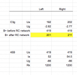
b. Here are the latest measurements (both channels, see attached). Note the differences highlighted in yellow. In particular, the voltage drop after the B+ RC network just prior to the IT feeding the C3g. I am using new 10k ohm caddock resistors (25 watt) to drop the voltage. Yet, there is a 10V difference between channels (211V vs. 201V). This in turn is causing the 10v difference at the C3g plate.
Voltage before the 10K resistor is the same for each channel. So, why would the voltage drop vary by 10V?
Thanks, Pat
a. I created another thread that should have been left underneath this thread. Important information related to this project. Here is the link to the other thread. I would like to bring the group back to this original thread.
Help please: Bias and hum
b. Here are the latest measurements (both channels, see attached). Note the differences highlighted in yellow. In particular, the voltage drop after the B+ RC network just prior to the IT feeding the C3g. I am using new 10k ohm caddock resistors (25 watt) to drop the voltage. Yet, there is a 10V difference between channels (211V vs. 201V). This in turn is causing the 10v difference at the C3g plate.
Voltage before the 10K resistor is the same for each channel. So, why would the voltage drop vary by 10V?
Thanks, Pat
Attachments
Last edited by a moderator:
Read the voltage directly across each 10k resistor. I think you will find one side drawing more current than the other.
Update: I measured both resistors. They are both 10.02K.
Then, I switched the C3g tubes. The voltage drop variance followed the C3g tubes. So, it appears to be tube related.
Then, I switched the C3g tubes. The voltage drop variance followed the C3g tubes. So, it appears to be tube related.
Something is not clear for me (C3g operating point).
If you measured voltages correctly, your anode current over 20mA, at 190-200V Uak region.
This is over the suggested 3.5W (Ia+Ig2) plate dissipation.
BTW -IMHO- the g3 connecting to "ground" is misinterpretations of datasheet.
At the triode connection the g3 potential ("0") is compared to cathode, not to more negative "ground".
Update: I measured both resistors. They are both 10.02K.
Then, I switched the C3g tubes. The voltage drop variance followed the C3g tubes. So, it appears to be tube related.
Read the voltage across them.
- Home
- Amplifiers
- Tubes / Valves
- C3G drives 45