With B+ 450V, and Bias at 30V, that works for the EML 45B, but only if you use Self Bias.
Fixed bias of 30V will only work there if you reduce the B+ to 420V.
Fixed bias of 30V will only work there if you reduce the B+ to 420V.
Sorry, my post was duplicated.
No way to delete this post # 62.
Moderator?
Help Please.
No way to delete this post # 62.
Moderator?
Help Please.
Last edited:
Hi Pat
1. Your 450V B+ is with or without load? If without load, then it will be less when running. Try using Duncan Amp's PSU to simulate your power supply. Feel free to pm me.
2. Your 100k ohm bleeder resistors are 3 Watt or more, right? Check ohm's law here.
3. You cannot measure ripple with a DMM. But don't rush out to buy an oscilloscope...
Ian
ps. I am not a fan of mercury vapor rectifiers because of reasons already mentioned. There are perfectly fine alternatives. I use Television damper diodes, which have a really great slow start (but have 6.3V heaters). The slow start helps make your 45's last longer... or for a 5V replacement, you could use GZ34/5AR4 instead.
Last edited:
Hi Pat
1. Your 450V B+ is with or without load? If without load, then it will be less when running. Try using Duncan Amp's PSU to simulate your power supply. Feel free to pm me.
2. Your 100k ohm bleeder resistors are 3 Watt or more, right? Check ohm's law here.
3. You cannot measure ripple with a DMM. But don't rush out to buy an oscilloscope...
Ian
ps. I am not a fan of mercury vapor rectifiers because of reasons already mentioned. There are perfectly fine alternatives. I use Television damper diodes, which have a really great slow start (but have 6.3V heaters). The slow start helps make your 45's last longer... or for a 5V replacement, you could use GZ34/5AR4 instead.
Ian,
The 450V B+ was without load.
Using PSUD, here is what we get:
320V secondary -> 5U4GB -> 10uf -> 10H -> 50uF
Ripple 84uV p-p
B+ 387V
I am leaning towards a 274B rectifier at this point. I have a 5U4GB in stock, so currently using it for my breadboard. I also have a 274B Sophia Electric Aqua which permits C1 <= 40uF.
My bleed resistors are 5W, 330K and working OK from a voltage drainage standpoint.
Pat
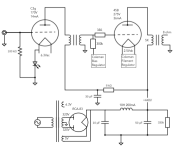
Team - progress. Please see the latest schematic, v3.0. I decided the following:
1. Using Rod Coleman DC heater regulators on output tube.
2. Using Rod Coleman Fix Bias regulators on output tube.
3. For this first iteration, I will use the EML 45B. This will allow me to play with higher plate voltages and current.
4. CLC power supply, for now. Later iterations will likely move to LCLC.
Thank you, everyone, for your help. If you see any glaring errors, please let me know.
Pat
Attachments
2. Using Rod Coleman Fix Bias regulators on output tube.
This regulator is shunt type. Connect regulator -negative- output (positive is on ground) to IT secondary "lower" point (instead of Gnd) without any resistor.
Attachments
Last edited:
Team - what do you think about using the DRD and ultrapath solution (aka monkey). From what I have read, this help increase power output significantly & lowers distortion. Not much to change to the circuit to implement this. I have read where DRD can be dangerous is the output or input tube is taken out of the socket while the amp is powered up. Or if the output tube breaks contact with it's pins. Other than that, I haven't heard of any downside to the DRD. Thoughts?
banpuku,
Power Supply:
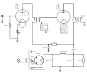
For the type 83 mercury rectifier, your schematic in Post # 65 is missing 3 parts . . .
A switch from the center tap of the B+ secondary to ground (Wait until the 83 filaments warm up the Mercury, before closing the switch from the center tap to ground).
And, when you turn the amp off, be sure to return the center tap switch to the Open position.
Otherwise, the next time you turn the amp on, the tube may arc or explode.
And,
Then there is another problem with using an 83 mercury rectifier.
Suppose your amp is on, and then the power mains goes out. Your center tap switch is closed. When the power mains goes back on, the mercury is not warmed up . . . and you get either arcing or an explosion.
You need two 56 Ohm resistors. Put one in series with each plate of the 83 from its respective high voltage secondary winding.
DRD versus Interstage Transformer:
Both of these circuit topologies can drive the output tube with grid current.
That allows for more power out.
The common RC coupled circuit can also drive the output tube with grid current . . .
But that grid current charges the C of the RC network, re-biases the output tube to a lower current. The result is the transient unidirectional output power is increased, but that is followed by Less output power.
All designs have tradeoffs.
Any engineering problem has at least 100 solutions, of which at least 3 solutions will actually work, but only if those 3 solutions are properly applied.
"All Generalizations Generally Have Exceptions"
Power Supply:
For the type 83 mercury rectifier, your schematic in Post # 65 is missing 3 parts . . .
A switch from the center tap of the B+ secondary to ground (Wait until the 83 filaments warm up the Mercury, before closing the switch from the center tap to ground).
And, when you turn the amp off, be sure to return the center tap switch to the Open position.
Otherwise, the next time you turn the amp on, the tube may arc or explode.
And,
Then there is another problem with using an 83 mercury rectifier.
Suppose your amp is on, and then the power mains goes out. Your center tap switch is closed. When the power mains goes back on, the mercury is not warmed up . . . and you get either arcing or an explosion.
You need two 56 Ohm resistors. Put one in series with each plate of the 83 from its respective high voltage secondary winding.
DRD versus Interstage Transformer:
Both of these circuit topologies can drive the output tube with grid current.
That allows for more power out.
The common RC coupled circuit can also drive the output tube with grid current . . .
But that grid current charges the C of the RC network, re-biases the output tube to a lower current. The result is the transient unidirectional output power is increased, but that is followed by Less output power.
All designs have tradeoffs.
Any engineering problem has at least 100 solutions, of which at least 3 solutions will actually work, but only if those 3 solutions are properly applied.
"All Generalizations Generally Have Exceptions"
Last edited:
For the type 83 mercury rectifier, your schematic in Post # 65 is missing 3 parts
Yes, I do plan on having a separate switch for the filaments (including the 83) and the B+.
One thing to remember about type 45 tubes.
The filaments are rated at 2.5V, and 1.5 Amps.
That let the designer of a radio or amplifier plan his 2.5V filament transformer current, so that it would not get hot.
They did not use current sources to run filaments back then.
But I have seen some very old type 45 tubes from major manufacturers of that long ago time,
which only draw 1.2 Amps at 2.5V.
If you run those old 1.2 Amp tube filaments from a 1.5 Amp current source, the tube life will be very shortened.
Not everybody who reads this thread will be able to afford an EML 45B.
In fact they may not even be able to afford a NOS 45, so they will get less expensive Used 45 tubes.
That is what I did.
And I did not use a 1.5 Amp current source to run those filaments, instead I got long life out of used very old tubes.
What a great sounding amplifier that stereo SE 45 amp was.
Just sayin'
Last edited:
> If you run those old 1.2 Amp tube filaments from a 1.5 Amp current source, the tube life will be very shortened.
This is true!
But one might hope there are no filament supplies out there with fixed-current output. This would be wrong for almost every case (with exceptions for WE101D, WE102D etc and STC 3A/109-series which are designed to be heated by a specific current).
Current-driven heating is correctly implemented for voltage-specified filaments, when the current can be adjusted (or servoed) to the correct filament voltage, as closely as possible.
This regulator is shunt type. Connect regulator -negative- output (positive is on ground) to IT secondary "lower" point (instead of Gnd) without any resistor.
Thanks, Bela. This is exactly how it should be done.
Thanks, Bela. This is exactly how it should be done.
Please see attached and confirm / comment changes for the bias regulator. Thanks!
Attachments
Bias connexions are good.
Some ITs have a C or RC termination on the secondary, to give optimal pulse response.
It's optional, but worth trying whatever the manufacturer recommends.
Some ITs have a C or RC termination on the secondary, to give optimal pulse response.
It's optional, but worth trying whatever the manufacturer recommends.
Rod Coleman,
I was not trying to downgrade your filament supplies.
I just know that some beginners who read a thread like this one,
will not check your instructions as to how to apply certain filament supplies.
In euro21's post # 68, the 45's filament supply in the schematic was listed as a 1.5A current source.
That is the kind of thing that beginners do not know, but need to be advised of.
In my post, I should have referred to the schematic in post # 68 as having a possible problem
(for those 1.2 Amp 45 tubes).
Last edited:
It's okay. I did not read it as an accusation! But actually, I have seen a number of commentators writing that current-drive supplies are "bad" for this same reason; and an explanation will not hurt.
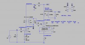
Euro21s post is an LTSPICE screenshot, so the nominal current would be expected.
Euro21s post is an LTSPICE screenshot, so the nominal current would be expected.
Rod C.
Thanks for the education. I have never used LTSPICE. They need to improve the labels to have a little more info. I know, that makes for more space, and a larger schematic.
I am an analog guy.
For example, I do my own calculations for B+ and DC filament supplies.
Calculate resonances of CLC, ripple, DC voltage, supply impedance, etc.
Decades ago, a couple of us got caught by the resonance in a CLC supply.
Similar to an RF pi filter in a transmitter, it resonated at low audio frequencies.
The scope display was nothing short of hilarious! LOL
I will take my mistakes, pick my self up, and take corrective action.
There are wonderful software tools out there, powerful & time saving too, but not for me.
Software and I just do not get along.
If you were a regular reader of BoB Pease in EDN magazine (Pease Porridge), you will know some stories that he told.
One was a student or newly graduated engineer who asked him how he optimized an IC after the chip had already come out of the foundry (the question was, how do you make changes to the chip for the "second round design"). The answer was classic.
Another story was of a new graduate engineer who wanted to become an analog engineer.
Bob said how long have you been tinkering?
At a company I worked for, an engineer designed a CLCLCLC RF low pass filter. It needed to have more than 60dB out of band rejection. He built it on a copper clad board, it worked great!
Off it went to the PCB layout person, and it came back with only 20dB rejection. I spotted the cause right away.
The SMT L (solenoid inductors) were all in a straight line . . . couple from 1 to 2, couple from 2 to 3 . . .
Take off the middle L, turn it 90 degrees, now it works. Time for another PCB layout.
Last edited:
> BoB Pease in EDN magazine (Pease Porridge),
Yes, I had EDN & Electronic Design in my days of corporate design work; Pease Porridge was a good column. He threw that computer off the roof at National, too - angry at 'being lied to by SPICE'!
Linear Tech weree in on the Analogue Fundamentalist line, in their early days - see the example in the pic.
One must not allow SPICE to dictate the terms of any designs, and understand the limitations very carefully. Building and measuring carefully are still necessary! But LTSPICE is good enough and fast to work with, and eliminates a lot of BAD potential circuits, leaving the better ones to be built and characterised.
The picture is from the Subject Index of the LT Application manual, 1987 year.
Attachments
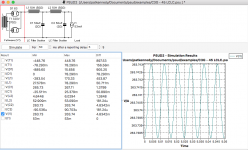
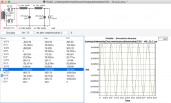
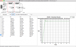
Looking to move towards a LCLC instead of a CLC. Here are the PSUD results. As this is my first time using PSUD, I need your input on whether or not these results look good.
4.8mV p-p ripple
181uV p-p ripple
Thoughts?
4.8mV p-p ripple
181uV p-p ripple
Thoughts?
Attachments
- Home
- Amplifiers
- Tubes / Valves
- C3G drives 45