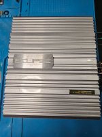
I decided to start a new thread on this amp as the other thread dealt mainly with replacing the AM-1, AM-2 sealed predriver modules.
So going back, I received this unit knowing that the owner mentioned it got wacked with over 130VAC during a storm and a power surge.
It took out all 4 front 6 amp fuses for the -50,+50 supply . He had someone look at it and some output transistors were blown on the right channel and then it was never finished and sat for 10 years. So I thought I would take a chance and see if I could repair it. As I mainly repair tube gear, I haven't really worked on any SS amps with this many transistors in it.
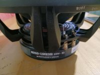
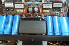
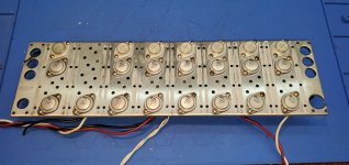
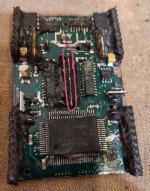
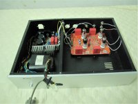
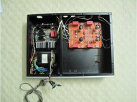
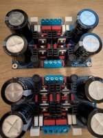
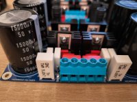
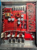
Not sure if anyone is familiar with this unit, it has a massive power transformer and caps creating -50, +50 for the power transistors and also feeding back to the predriver board and also +75, -75 volts also feeding the predriver board. Taking the power module apart is quite a task in these amps. You have to unscrew the predriver module( more on that later) , then there are 4 PC board which are soldered and have to be removed before getting access to the power output transistors. Then you have to unscrew each heatsink for 3 transistors.
Each channel has a pair of NPN feeding 4 PNP(-50) and then 2 PNP feeding 4 NPN (+50). The right far bank had 2 transistors removed (which had been worked on), and in a bag came with a few more NPN predrivers and a blown PNP and some screws.
So what I really should of done was just order all new transistors from Mouser/DigiKey On semi makes them. The part #'s on the original transistors are AR part numbers and here are their equivalents for reference.
300024(NPN) MJ15015
300025(PNP) MJ15016
300027(PNP)MJ15004
300028(NPN)MJ15005
There are total of 24 transistors in the power section of this amp. My mistake was to look for and shorted or out of spec transistors and replaced them. As only having a cheap transistor checker I got them as close as I could matched (hfe) and there were no shorts and more. I then got reading that a lot of issues were caused by the predriver board.
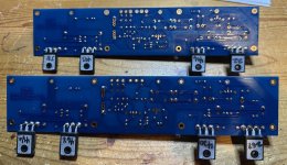
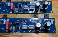
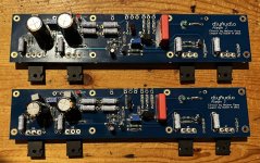
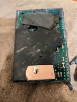
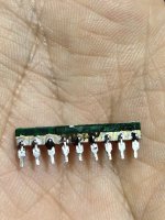
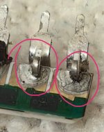
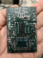
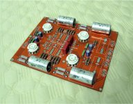
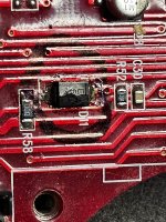
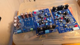
The predriver board consists of 2 sealed AM-1, AM-2 IC type modules which have quite a few transistors in it and cannot be purchased any more. One fellow on another thread(repairing the AR 110 modules) has designed some replacement modules to replace the AM-1, AM-2 units.
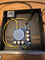
I verified that mine were ok and I had signal through both. After fixing the bad transistors I fired the unit up slowly on a variac and no shorts or smoke and voltages were ok.
I had gain in both channels . The left seemed a bit bit lower but with a 1kHz signal across a 100 watt 8ohm load , I scoped the outputs and sine wave looked good, but I had some neg DC offset, meaning some DC was leaking onto the speaker terminals. In some amps there are gain and DC offset controls to adjust this, but in these amps there are none.
Reading more, the DC offset in the output is most likely caused by mismatched transistors, or in reading the other post some of those AM-1. AM-2 modules could cause the neg offset.
I went over the output section again replacing a few more transistors and then somehow turning it back on I was getting the full -50v on the output. It looked like a short somewhere.
Well pulling my hair out I decided to replace all the outputs and now I have less than 20mv on each channel. One or more of the original transistors must of have been bad and not picked up by the tester until full DC power was applied to the output.
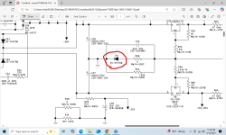
I have attached the schematics. I am now in the process of working on the predriver board with the new boards that another member designed.
I will continue this later, hopefully this helps someone else.You can get bigger versions of these schematics from the AR site.