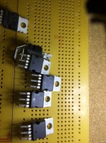
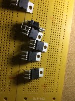
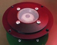
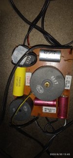
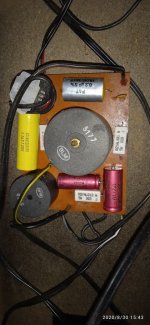
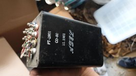
WTB-Transformer set(s), OPT and Power

Hi all. I'm just getting back into tube audio after a couple year's hiatus. I'm looking to build an amp, or a couple of mono blocks. Topology isn't important, I'll go pp or se...or even pse....just looking to get north of my current system power, which is about 35wpc maxed out. Reason I'm so open is just for the joy of the build anyway, and for budget purposes. I don't want modern import opt's, so I figured I'd post here and see what anyone has sitting on their bench not being used or planned. I'd rather pay a fellow builder a fair amount and share the project than just order some 100w Hammond Cores. As for power transformers, if it's north of 200-250ma and 400v I'm game.

So yes, if anyone has a pair of some larger opt's and/or power transformer(s) please do pm me.

Thanks much everyone

Loren
Motorboating---Help Please!!

I built Leak TL/50 Plus from scratch ,point to point. The only thing I changed
is the layout: Kt88, EF86, 12ax7 KT88 in that order. All voltages appears fine.
The amp is playing wonderful untill I connect the Feedback. Then it started motorboating at a rapid pace. OK I know for sure that is connected right. It's
Edor transformer and it was in another amp. I tried many resistor but it only
stop if I use like 1 or 2 megs.
OK, I am a dilettante and I am working with only a mulitimeter. Any help or
suggestions will be appreciated.http://44bx.com/leak/Leak/Circuits/tl50_ecc83.JPG

Stereo or 2.1 PC speakers

I love listening to music and have a reasonably good audio system, but I have always wanted to build my own speakers. The thing is, I know nothing about designing enclosures to get the best out of a selected driver or drivers... and I don't want to make an expensive mess, so I figure I should start small and simple and am therefore thinking that some new speakers for my PC are in order - after all, I sit at my desk many hours a day.

My initial thoughts on the matter are that I could build a pair of stereo speakers using 3" or 4" full range drivers, perhaps augmented by a single passive sub if required (if so, I'd need to make that too).

I have a total budget of around £250 including speaker parts and the amp for the project. With respect to the amp, I'm definitely open to suggestions, but I'm thinking about something like the SMSL SA-50 if no sub is required, or something like a Dayton DTA-2.1BT2 100W 2.1 (or a cheaper alternative) if a sub is required.

So, here are the physical design limitations... because I have a large monitor and don't have any space at the sides to put any speakers, the speakers will need to fit on the desk under the monitor. For that reason, they will need to be limited to the following maximum dimensions 20cm (w) by 18cm(h) by 20cm(d) which isn't great - although I guess the height could be increased if part of the cabinet went up behind the monitor (obviously not where the driver is on it), in which case the height limit could be increased to about 45cm.

Given those dimensions and budget, do you think that I'd be able to build speakers that have a reasonably flat response and don't need a sub to get down to around 50Hz (f3)? It might be worth stating that they don't need to go very loud. If not, I could build a sub too, but that would need to fit under my desk behind a vanity panel, and for that reason, the maximum dimensions for the sub enclosure (including excursion/breathing room for the driver) are 40cm(w) by 65cm(h) by 28cm(d).

Although I have a background in physics and some experience in electronics, please treat me as a complete novice and if there are any blogs/pages/papers that you think would be good for me to read before progressing, please let me know. Reading through numerous posts on this forum, I get the impression that it takes a lot of time, experience and effort to become an expert.

Many thanks.

Transistor subs for Marantz Nineteen driver board

Hello all, I have a model Nineteen receiver that is doing excellent with the exception of one channel having offset that is all over the place. It fluctuates between -150mV and +150mV while the other channel is at 5-10mV. I removed all of the transistors from the board And measured them with a Peak Atlas DCA75 meter and they all measure okay, though they’re being measured a very low voltages. The electrolytics are new and the carbon comp resistors were replaced.

Could it be caused by something other than a transistor? A diode? A ceramic cap?

Anyways, here are the transistors on the board per manual.

34-1004
34-1005
34-1007
34-1014
MPSA56

Unfortunately Marantz part numbers make it hard to cross reference parts lol.

For the 34-1004 and 34-1005 Ive read the 2N5320 and 2N5322 would make good replacements. If that’s true, how about the MJE243 and MJE253? Specs would say they’d be equal or better.

For the 34-1007 Ive read the 2N3906BU is a good option and I have plenty of those.

For the 34-1014 Ive read the KSC945C is an option. I don’t have any of those, but have read in certain circuits the KSC1845 is good and in others the

Does anyone have a good suggestion for the MPSA56? I have a large number of transistors and hope I have something on hand.

I only really plan on replacing the transistors creating the issue. Are any of the transistors here supposed to be hFE matched? (Differential pair)

If anyone could point me in the right direction on where to start I’d be very grateful. If you’re ever in Oregon I’ll owe you a drink.

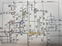
Here is a pic of the circuit and have colored the transistors

34-1004 Blue
34-1005 Green
34-1007 Red
34-1014 Orange
MPSA56 Purple


Thank you,
Dan

Attachments

  • 15BD25AA-9309-4F81-BFAE-47BA842216A1.jpg
    15BD25AA-9309-4F81-BFAE-47BA842216A1.jpg
    1,009 KB · Views: 434

PCM1795 Reset Function

Hello,

Im a bit confused with the power-on/external reset function of this DAC. In my circuit im using CS8416 as the receiver and I have the RMCK of CS8416 driving the SCK of PCM1795. Now the datasheet of the DAC says that the initialization sequence requires 1024 system clocks and after that the DAC is in its default reset state.

From my understanding this pin is only needed to set the registers in the device to their default states after power-on and these default states can be programmed before.

Now the problem is that CS8416 wont be driving the SCK pin if its not receiving anything which means that I must use the external reset since there will be a delay between power-on and system clock activation (the datasheet mentions this).

So I think I need some kind of a circuit that will supply the clock to the SCK pin and pull the RST pin low and then quit after 1024 clock cycles. But since this pin will also be connected to the RMCK pin of CS8416 Im not sure if applying voltage to this pin will damage the CS8416.

Other idea is that I have a mcu which will set up all the register on power-on then I just dont use this pin.

I assume Im either overcomplicating this and theres a simple solution or Im just not understanding the datasheet.

Can somebody give me a better idea or correct me if Im wrong?

Looking for Channel Swapping Software for Windows

I'm looking for a program that allows me to turn a couple of my surround channels into subwoofer channels (or mono, if nothing else) so I can power my subwoofers with the same amplifier (7.1 capable) as the rest of my 5.1 setup. Windows doesn't seem to have native subwoofer presets that allow anything other than a subwoofer signal that gets passed on to a dedicated subwoofer amplifier.

I'm hoping to avoid buying a second amplifier just for some decent bass! Any help would be appreciated!

Edit: I also should mention that I'm trying to do this over HDMI. My previous receiver had analog multi-channel in, so I could simply plug the subwoofer out into one of the other channels. Unfortunately, my new receiver doesn't have more than analog stereo inputs, so I'm forced to use HDMI if I want proper surround.

Simplest schematic of amp within the chip?

Hi, I've been lurking for many years with great interest in pass, jlh, susan parkers zeuss, and other simple amps (the de-lite is special imo). Now the itch to solder something is growing too strong. however i do not have a lab or testing equipment or experience. i wish to use low voltages, less than 75v but preferably around 10-36v. power is not a consideration 1-10 watts, 4-7watts would be fine. distortion as long as it is relatively benign is fine too. i really like the sansui 101 which has distortion of 0.8% i think i'll be happy if distortion is less than 4%. must be able to drive in to 2ohms. preferably class a or a/b but i'll look at others.


My main criteria is this. the chip that i want to experiment with must have the simplest internal structure possible while maybe only needing a single gain stage before or no gain stage. no opt, but input transformers is ok.


im thinking something like the ruby amp Ruby


here's a link to the pdf of the chip which shows an internal schematic https://www.ti.com/lit/ds/symlink/lm384.pdf?ts=1600199329563&ref_url=https%3A%2F%2Fwww.google.com%2F


are there any others you could recommend?


i intend to build some speakers that will be 96db efficient on average with a high qts of about 1.5ish.


many thanks and i hope you come up with some interesting suggestions!

Help with MOV expertise?

Working on non-audio problem: repair of auto Electronic Brake Control Module (EBCM).

My car is famous for common EBCM failure. The EBCM is comprised of 2 PCBs, 1 a big relay board holding 2 big 50A or so relays, and 1 an SMT micro board.

One of the specialized repair houses released this ambiguous blurb for one of their repair options:
Surge suppresion upgrade is available for your repair. This upgrade is much like the power strip on your home computer. Every time your EBCM receives power from the ignition, it goes through a number of housekeeping routines to make sure everything is working before it activates itself for operation. One of the checks that it performs is to make sure the ABS pump is attached and working correctly. For this procedure to work, the EBCM must send out voltage to the pump for a few milliseconds or just long enough for the module to determine if the pump is in good working order or not. Unfortunately, when this happens, a large voltage spike is generated by the pump. This voltage spike can be very hard on EBCM electronics. We suppress this spike so you don't have problems caused by your ABS system.

As the EBCM is quite tightly packaged, my guess is the are just adding an MOV or multiples in parallel.

I am trying to figure out which MOV model. Looking at the Bourns datasheet, the lowest voltage offered, the MOV-14D180K, has specs of:

Max Continuous Voltage: 11 Vrms, 14 Vdc
Voltage @ 1mA DC: 16 Vmin, 18 Vnom, 20 Vmax
Voltage @ Class Current: 10 A, 36 Vmax

Does this sound right? Or is the activation threshold too close to the car's operating voltage? AFAIK MOVs are used for 120V residential surge suppression are usually nominally described voltage much higher than 120V.

My car does run at 14 Vdc typical (by voltmeter I added, not stock gauge cluster).

Spark plug wire for tubes with a top cap?

Spark plug wire has well thought insulation layers very high dielectric strength, its very flexible, the boots can be repurposed to grommet into the chassis, and it looks cool and safe to the touch due to its thick insulation.

Construction-wise, there is straight copper wire, carbon core, spiral wound types and other methods of EMI reduction.


Do you think the straight copper spark plug wire would be a good choice for top capped tubes?
The wire I have just looks so dinky coming off a top cap. I'd replace the actual terminal to the tube with the correct size for the tube of course, or just fix a proper sized ceramic boot.


Constructions:

Getting Wired: Spark Plug Wires 101

A typical copper core set:

Amazon.com: JDMSPEED New 10.5mm Spark Plug Wire Set Replacement for HEI SBC BBC 350 383 454 Electronic: Automotive

Do inuke nu6000dsp speaker outputs have a common/ground?

As an alternative solution to opening up the amp and adding relays to get rid of the turnoff thump I'm looking at putting a relay on the speaker outputs.

If the speaker outputs have a common ground I could use a single relay.

I got out my DVM to check but I can't tell what's what with the hard to access Speakon contacts, and the subs are buried in walls so it's hard to check at that end.

Schematic starts on p.3 here if that helps (it's over my head):

BEHRINGER INUKE NU6000DSP SERVICE MANUAL Pdf Download | ManualsLib

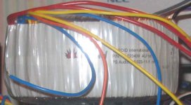
FS: 725VA, 43VAC transformers

TOROID International PN TI-023439 AU Iss 3
PS Audio: 13-023-11-1 rev G

725VA
43VAC 16A
14VAC 1A
58VAC/CT 1A

6" diameter, 3" height

I have 3 (though the pic only shows 1)

Asking $55 ea + s/h, or best reasonable offer

Also will consider trades for trafos that will give me about +/- 35V around 350-500VA... Combination of trade and money is good too..

Other trades I will accept (not necessarily an even swap) are:
-Adire Audio Extremis or Tempest or Brahma or Tumult or Maelstrom or possibly Shiva
-Anything by Ascendant Audio
(maybe more later)

Attachments

  • 1trafo.jpg
    1trafo.jpg
    39.4 KB · Views: 501

Dual rail regulated PSU made of two identical regulated PSU

When using two 0 +V supplies to make a -V 0 +V supply, it can be done under the condition they are floating, so one can connect the +V of one to the 0 of the other.
This precludes using a transformer with a center tap secondary.
This asks for two independent secondaries with independent diodes and cap stuff.
A transformer with two independent secondaries, or two independent transformers.
I know this works, but I suspect there are drawbacks.
Are they dual secondary transformers dedicated to this application that limit unwanted interactions ?
Is using two transformers effectively removes unwanted interactions ? They usually have the primaries in parallel.
What are the drawbacks and appropriate solutions ?

2sk369 as current source or sink?

Wha do you think about using 2sk369(very high ransconducance j-fet) as a curren source or sink? I mean pros and cons...
I need a 5ma low noise current source o bias some zenners and i have some of these but i remember some people not recommending high transconductance transistors against bf256c .I was thinking more about using a tl431+bjt composite ccs to be honest , but a 2sk369 fet looks like the simplest way to achieve it.


I also have some 2n5464 (p channel) that could do the job, but the current spread goes as low as 2ma for 0v Vgs and i need a solid 5ma current source.J112 , 174, 2n5460, 2n5457..I know that higher GS resistors usually give better current regulation, but 2sk369 graphs look pretty linear even with a 20 ohms source resistor.
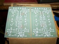
Might probably be better to use two sk369 in parallel with like 51 ohm source resistor as a bzx 55 zener would still work fairly well at a total of at 4ma.
The current source noise is an important factor for me as well.

Attenuation from speaker level to line level balanced

I would like to generate line level outputs, for driving active speakers, from speaker level outputs. I have the added complication of the active speaker input being balanced. I think a 20dB attenuator might be about right normally but going from unbalanced to balanced (by grounding the -ve balanced speaker input) will also affect the attenuation. Can anyone throw some light on this for me? And also suggest some suitable resistor values for the potential divider?

how might I cut and open this klam's aperture without ruining everything?

I'm old, vision doesn't converge and not a good woodworker to begin with.

maybe take a 2 foot flexi ruler and draw new lines which open to full width at the end? A jigsaw blade would have to be shortened as to not bang the panel below the wings. Ive not driven for 25yr. and know no one locally who could/would attempt the feat.

Someone with a router and skill could do it nicely - I'm worse than dead broke so can't send them 2000 miles for an operation.

KZzQ7lt.jpg


My builder may have gotten a reference off so the nose looks like so

TqYxvX5.jpg


Rather than it should look as with Carl Neuser's original:

sVgsqkb.jpg


If I were rich, I'd have a pair built correctly as a nice size to be able to lift
onto tripod and have some punch. Then again, aybe a 38 degree coupler would work as well or better ?

Hello to audiophilists!

Hello,

after a few contributions, I will introduce myself briefly afterwards.

My name is Oliver from Germany (near to Frankfurt) and music was and is a constant companion in my life. I'm currently looking for a gapless and bitperfect solution with my Odroid C1+ (RuneAudio already tested, DietPi still in progress).

Sometimes I'm a kind of old-school (53 years) about some things: grown up "analog", no streaming services (a little webradio), buying CDs for ripping (keyword: "original backup" 😉)...but open to modern technology.

My (main) music system (men's room 😀):
  • Synology DS716+II media server (flac 16/44,1-24/96bit)
  • Audiolab m-one (Amp, integrated DAC 32bit/384kHz)
  • KEF LS50 (white/blue)

2nd "easy listening" (living room)
  • Marantz CR-M511 (DLNA-Synology)
  • Bose Acoustimass 5 (acrylic, stereo with dual-cube speakers...rare and quite nice)

Regards!

Question for vinyl playback experts

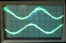
I just had the idea to hook up my oscilloscope to the output of a new Step-Up Transformer. I used the test tracks of the HFN&RR Test Record HFN 001. At the Bias Setting track (Band 9, 300 Hz L+R at +18 dB) I got the waveform on the attached picture. The top of the signal is blurred, like the stylus has lost contact with the groove. But it is not incorrect antiskating, because it caused much more evident distortion of the sinus shape, when I misadjusted it.
What could be the reason of this disturbance?

My system is Thorens TD160 Super turntable, Mayware Formula IV arm, Denon DL103 cartridge, Lundahl LL1678 step-up transformer, 47k termination.

Attachments

  • signal.jpg
    signal.jpg
    257.5 KB · Views: 261

Inline passive crossover

I am currently running a pair of Jeff Bagby's "Kairos" stand mount speakers (slightly modified), using the great SB Acoustics ring radiator tweeter, and 6" mid.

They are quite good, and image amazingly well. At least for now, I am very happy with them.

In the long run, I want to build Jeff's 10" woofer modules, which is not a subwoofer, but designed to basically turn the Kairos into a true 3 way system. The Kairos sit on top of the woofer modules, kind of like a WATT/Puppy.

At the present, I am running a very good powered sub, but the Kairos are running full range. What I want to do in the mean time, is to filter the low bass out of the Kairos, using an inline passive crossover.

My question is, when calculating the value of the capacitor, I am using the input impedance of the amp, which is 50K ohms. Calculated at 100 hz, this is giving me a cap value of .032 micro farads.

Does this sound correct? And are there any audio quality caps at this value?

Thanks!

Oscilloscope versus usb card?

Oscilloscope capability is expressed in MHz (20MHz .. 100MHz, etc.), usb acquisition card working as oscilloscopes have their capability expressed in samples/s, as far as I understood.
Is there a direct relationship between samples/s and MHz?

If the usb card acquisition is let's say 100ks/s, does it mean 100KHz? Kind of low compare to simple/old oscilloscopes rated for 5-10MHz.

Not having an oscilloscope, I am interested in the two following items:
- EspoTek Labrador Board (EspoTek Labrador – Official EspoTek Online Store),
- iCP12B - usbStick (iCP12B (1mV+) - usbStick (Micro USB DAQ, PC Oscilloscope, Data Logger, Frequency Generator, PIC18F2553 IO Board)).
Any member tried them?
How do you think they compare versus simple low end oscilloscopes?

AES: Evaluating Electrolytic Capacitors Specified for Audio Use

AES: Evaluating Electrolytic Capacitors Specified for Audio Use: A Comparative Analysis ......
This paper is Open Access

This paper provides a number of comparative, quantitative evaluations of 10 different makes and models of electrolytic capacitors. Models range from expensive parts specified for use in audio circuits to low-cost general-purpose parts. The datasets comprise out-of-circuit electronic measurements, total harmonic distortion (THD) fast Fourier transform (FFT) sweeps, and cumulative distortion products resulting from 31-tone stimulus performed on the components in a circuit designed to emulate a typical line-level audio recording and mixing console. Results are examined in an effort to identify any measurable properties that may distinguish “audio capacitors” as outliers from their general-purpose counterparts.

I have only glanced at this; have not read it.

Attachments

  • Anderson,IanZ-42.gif
    Anderson,IanZ-42.gif
    36.7 KB · Views: 690

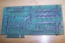
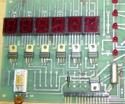
Box of unknown boards?

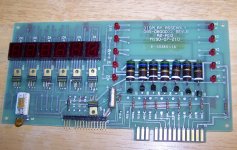
Here's a few more boards I found in the last cleanout, these were in a box, about a dozen per box or so. The cabinets were from a major university, but they also had old US Navy markings on them. I'm thinking maybe these were for some sort of test equipment? I don't think they're audio related but I figured maybe someone here might have some idea what they're from.

The display is LED.
Its roughly 8.5x4.5" in size.

Any idea what it may have been for?

Attachments

  • 101_0015.JPG
    101_0015.JPG
    767.7 KB · Views: 162
  • 101_0016.JPG
    101_0016.JPG
    789.6 KB · Views: 169
  • 101_0014LS.JPG
    101_0014LS.JPG
    474.8 KB · Views: 164
  • 101_0014RS.JPG
    101_0014RS.JPG
    385.1 KB · Views: 166

PWR AMP Ovation E amp

Hi all,
I am trying to simulate the OVATION E AMP, with micro cap 11, did some one built it, the schematic i have includes 2SC3503 2SA1331 that i don't have in my library, i change them to BC547C BC557C, the simulation shows that all NPN power transistors are off state.
I am asking if some one built it and is running properly.
Thanks a lot for any kind of help.
Ovation e-Amp: A 180 Watt Class AB VFA Featuring Ultra Low Distortion
Best regards,
Williams

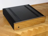
Rod Elliot P101 amplifier for sale

I am selling Rod Elliot p101 mosfet power amplifier. The amp is very good sounding unit due to it`s simple design and use of quality parts.

You can read more here: http://sound.westhost.com/project101.htm

My amplifer consist of 6×4700uF (80V) Nichicon caps and 400VA toroid transformer per channel. For protection it uses two soft start units and DC protection device from Vellemann. It will produce around 120 watts per channel on 8 ohm load, but you can push it up to 180 watts /8 ohm with different transformer voltages.

It makes also very fine visual appereance with crome front plate.

It is in perfect working condition waitting for new happy listener.

The price is very modest: 200 EUR + post costs

email: mark909@gmail.com

Attachments

  • p101.jpg
    p101.jpg
    86.2 KB · Views: 774

dc coupled amplifier dc spike

Hi Folks & Gurus!

so i recently acquired a brand new power stereo amplifier(dc coupled) , and a few things left me slightly puzzled. hoping some gurus here able to enlighten me.

I'm paring the power amp with my tube preamp(has capacitor at the output) , i measured using multi meter to confirm no dc output at the RCA terminals.

I also measured to ensure no DC offset at the amp speaker terminal , and result was less than 1mvdc.

However found that when playing slightly louder especially low frequency/ power demanding track would send the amplifier in to protected mode,according to manufacturer the amplifier has probably detect dc at the speaker terminal (threshold at around ~0.7vdc)? i did use my cheap multimeter to measure when playing those tracks , but the reading did not get anywhere near 0.7vdc, having said im seeing range from 30mv to 60mv before it trips , perhaps my multimeter not sensitive enough to pickup any spikes?

is it normal for a dc coupled amplifier to output any DC voltages at the speaker terminal when playing loud or playing low frequency notes?

Any response would be very much appreciated .

sorry that this is not a DIY related question , hopefully it is acceptable here 🙂

ps * amp is kinki studio ex-m7

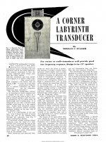
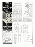
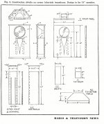
1951 article "A Corner Labyrinth Transducer" by Noman C. Fulmer

from the November 1951 issue of Radio and Television News magazine.

Here's the associated patent

https://patentimages.storage.googleapis.com/28/b4/ee/1278f2d1c7fe23/US2787332.pdf

Attachments

  • FULMER PAGE 1 1350.jpg
    FULMER PAGE 1 1350.jpg
    460.9 KB · Views: 131
  • FULMER PG 2 1350.jpg
    FULMER PG 2 1350.jpg
    358.6 KB · Views: 127
  • FULMER PG 3 1350.jpg
    FULMER PG 3 1350.jpg
    467.7 KB · Views: 117
  • FULMER PLAN.jpg
    FULMER PLAN.jpg
    420 KB · Views: 120

Novice question about integrated amp

I am currently using a Musical Fidelity M2si integrated amp as a preamp (picture below) with another power amp I have that outperforms the integrated's internal amp. The preamp in this integrated sounds fantastic. This is probably a bit of a weird and tweaky question, but I was wondering since the amp section is not really being used it would be nice to disengage it and was wondering if I removed those two fuses located near the two large filter caps in the amplifier section would it essentially turn off the amplifiers? Unfortunately I do not have a schematic. Literature says the Class A preamp has its own separate power supply windings separate from the amp and assume the preamp power supply is located to the right of the toroidal transformer? You can see the separate wires coming off the toroid (orange/green/white). If for anything efficiency alone, I wondered if it's possible by disengaging the amp section I could reap some audible benefits in the preamp performance. Any of you experts able to tell if those fuses are related to the power amps only and not the preamp? If I went ahead and experimented and removed them and see what I get would there be any harm in that? Thanks!

index.php

JBL 4343 - 4344 upgrade thread

Earlier last month I started this htread over on the Lansing forums.

As a result of some interesting comparisons with the Mox crossover and my Hot Rod Aleph I propose to re post relevent aspects of the project here.

Attached below is the latest revision of the framework for this project. We've added sections on basic setup and speaker placement and a section on improvements that can be made to the cabinets. We've also added an open ended section at the end for members to describe their more exotic modifications to their 4343 based monitors' drivers, cabinets, crossovers, etc.


Upgrade Modifications to the JBL 4343/4343B Studio Monitors:


This thread will describe several different upgrades available to owners of 4343 and 4343B Studio Monitors. Although we are focusing primarily on upgrades to the 4343 series monitors, owners of other Studio Monitors, 4344, 4350, 4333, etc, will find that many of these upgrades could apply to them also. The upgrades will be broken down into various upgrades starting with relatively simple upgrades up through a full upgrade of the drivers and crossovers. The basic framework here is to offer modifications that improve the performance of the 4343/4343B monitors while preserving their vintage appearance. A requirement here is that the speakers continue to look original. Therefore we will avoid any modifications to the cabinets or grilles. In addition, it is not within the scope of this thread to discuss how to restore the cabinet or grills. There are numerous other threads on the LH Forum that cover these aspects in great detail.


Setup and placement

1. Amplifier power recommendations

2. Connections

3. Room acoustics and monitor placement

4. Slot Tweeter placement- inner vs outer

5. Removing the top baffle

6. Measuring performance.


Upgrade 1 – System Maintenance:

1. Clean L-Pads, replace if necessary

2. Clean/improve terminations.

3. Testing condition of drivers and crossovers

4. Recones, refoams and new diaphragms.


Upgrade 2 – Upgrade 4343 drivers to 4343B spec.

1. Replace 2231A with 2231H

2. Replace 2121 with 2121H


Upgrade 3 – Bypassing the bi-amp switch.


Upgrade 4 – Upgrade the stock crossovers.

1. Replacing capacitors.

2. Bypass Capacitors

3. Charge coupling

4. Upgrade crossover to 3145 spec.


Upgrade 5 – Discussion on Bi-amping.

1. Pros and cons.

2. Active crossovers available on the market


Upgrade 6 – Upgrade drivers to 4344 spec.

1. Replace or recone LF drivers to 2235H

2. Replace or recone MF drivers to 2122H

3. Replace or rediaphragm HF compression driver to 2425J.


Upgrade 7 – Converting to Hi End Crossovers.

1. Internal vs External placement

2. Passive

3. Active


Upgrade 8 – Cabinet Upgrades

1. Improve internal bracing.

2. Modifying the top 4343 baffle

3. Modifying the bottom 4343 baffle

4. Cabinet and grille repairs


Upgrade 9 – Discussion on modern drivers.

1. Modern driver choices available today

2. Use of a subwoofer.


Upgrade 10 – Other Upgrades.

1. External Horns

2. 4345

3. Other upgrades

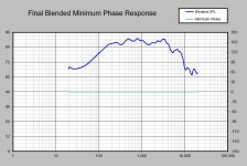
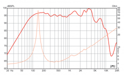
ARTA FR/IMP measurements seem off - Something Wrong

Good Afternoon All,

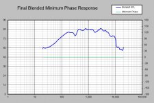
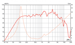
I'm new to measuring speakers, and i've been measuring a lot of guitar speakers recently with ARTA using Impulse Responses. I'm consistently getting a mid hump in the 400-1200hz range that is much higher than the manufactures posted results. It's so consistent, I feel like it's a measurement error, but I also don't fully trust the manufacturers posted results either. Hopefully someone has ran into this before or has some insight into what I can check into as far as setting or what not.

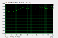
Attached are several examples comparing the measured vs. manufacturer results (please ignore dB as I didn't scale these). I have a couple other examples beyond these that are exactly the same. Also, for the hell of it, I measured a KEF LS50 and somehow measured relatively flat (no blended near field). Below is my set-up, hopefully someone can help me out here.

Focusrite 2i2 - Single Channel Measurement

Dayton 75w Power Amp - Have tried 2 other power amps with the same results

Dayton EMM-6 Mic - Compensation Loaded in ARTA (Also tried a DBX mic with same result)

Baffle - Same 2' x 2' for all speakers

Room - All of them in my house.... Including a 24' x 24' living room

ARTA Set-Up - Followed the instructions and Charlie Laub's white paper


Thanks,
Jason

Attachments

  • 620h - Measured.JPG
    620h - Measured.JPG
    108 KB · Views: 108
  • 620h - Website.png
    620h - Website.png
    84 KB · Views: 105
  • 820h - Measured.JPG
    820h - Measured.JPG
    107.1 KB · Views: 105
  • 820h - Website.png
    820h - Website.png
    81.1 KB · Views: 103
  • LS50 - Measured.png
    LS50 - Measured.png
    18.4 KB · Views: 111
  • ARTA settings.JPG
    ARTA settings.JPG
    52.5 KB · Views: 74

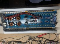
Lanzar opti 700x2

I got this lanzar opti in, amp was in protect. When checked it had shorted transistors (collector to emitter) on the right channel. All output Transistors were replaced.
Amp came out of protect and passed clean audio. When connected to a load, amp went straight into protect.
Checked output transistors and they were shorted (base to collector).

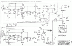
I pulled this attached schematic from another post, the values for the drive section are on point.
I pulled the pre drivers and drivers, all checked ok. Verified resistor values and all were within.
I then soldered in only one transistor per rail, again amp passed clean audio, when connected to a load (8ohm dummy) the amp went straight into protect.
The installed transistors were shorted base to collector.

I’ve compiled a list of components for the drive section to order and have all replaced.

The bias transistor is a C3200, I’m gonna replace those with MPs6521 due to availability.

Has anyone experienced something similar?

Attachments

  • lanzar_opti500x2.pdf
    lanzar_opti500x2.pdf
    778.8 KB · Views: 108
  • 5E251B47-745F-43D7-8EEA-226B123FF6B7.jpg
    5E251B47-745F-43D7-8EEA-226B123FF6B7.jpg
    1,019.1 KB · Views: 267

Adding Line Out / Sub Out to LG soundbar

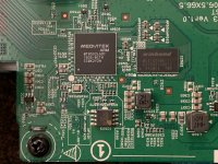
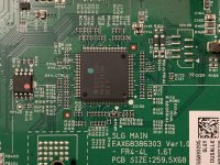
I have LG Soundbar with wireless sub. I am trying to add Line output, so i could connect a wired sub. I took some pictures of the boards and chips. If someone could point me in right direction on where to connect to get low level output. My second option is to add High to low converter but that doesn't always provide clean signal. ps9860 is Multi-channel Digital Audio Processor Eight-channels i think that should be where i could get a connection. If someone could confirm I'd appreciate it. I'm attaching link to folder with photos. Download files - Filemail

Attachments

  • IMG_3839.jpg
    IMG_3839.jpg
    954.4 KB · Views: 140
  • IMG_3849.jpg
    IMG_3849.jpg
    897.2 KB · Views: 151
  • IMG_3843.jpg
    IMG_3843.jpg
    1,005.4 KB · Views: 134
  • IMG_3846.jpg
    IMG_3846.jpg
    998.7 KB · Views: 146

Carver AL-iii plus mods and other info

I have only recently been into audio for a litte less than a year and a half. I sold my klipsch chorus I completely renewed(all mods you could think of and reveneered) and have recently bought a pair of these Carver AL-iii plus. I just wanted to make a post to see other's thoughts on the speakers and mods that are possible. Ive read a weak link is the inductors but was wondering if updating the caps would also be a good idea as well. Also, any good advice on placment? It is my first time having a dipole speaker(and ribbons) and I've read that placement and room treatment is important. Just messing around, I drapped towels over the back of them and I actually heard quite a difference in clarity of the ribbon. I dont want to compramise the soundstage with absorbtion though and have read possibly diffusion is the route to go behind the speakers.

Thanks for reading and any comments!
(other speaker I have at the moment are JBL4311)

Audio Precision Issue

Hello,

I have an Audio Precision Portable One Plus that seems to have developed a strange issue. At certain frequencies and levels, the distortion measurement reads 0.0000%. I know that the residual THD of the device is about .0015% from doing loopback measurements. It also passes its own self-test.

Can anyone enlighten me as to what this issue is, and how I can go about solving it?

WTB: MPSW56 - 1W BJT

Hi there:

I need 4 of these for a Hafler amplifier.

They were fairly common, inexpensive and easily available just a few years ago, but then Onsemi and Fairchild stopped manufacturing them. Now genuine ones are difficult to source and eBay is flooded with counterfeits 😡

Just checking to see if anyone has a few of these spare in his/her parts bin.

Thanks and stay safe!
Mayank

Tap aluminum heatsink

Hello,


I need to tap two M3 holes in aluminum heatsinks. I have 3 pass 3mm taps.


I don't succeed to have nice threads. They finish "too big hole" and the screw slips in them.


I had the advice to use only the last finishing one, as aluminum is a rather soft metal. This is a bit better, but still not very nice.


I have difficulties to start and stay vertical...


How do you do ?


Any tips to tap heatsinks ?


JMF

GAS Grandson - Bongiorno enhanced

Hi 2 all !

Sorry for reposting - I tried this before however it seems to get a bit lost at the end of this other thread.

I am currently refreshing my trusty old Grandson with a little help of "The Bongiorno" himself but I still could use a little help from some of you more technically knowledgeable enthusiasts.
I am therefore happy to share James' suggestions that I am sure will be of interest for some of you.

I really think these units deserve to be kept alive because for me a long experience clearly shows that - if ever - in terms of musicality only the most ridiculously expensive high end gear even comes close to what these machines delivered more than 30 years ago.

Back story is that I got the Thalia/Grandson combo in 1985 and I am obviously totally addicted to the sheer musicality of it.
I tried loads of other amps, even insanely expensive high end types (Pioneer, H/K Citation, Forté, Hafler, Bose, Chord, Yamaha, Crown, Magis, Bryston etc.) and while finding some preamps that I could live with (and finally went for a Technics SU 9070) power amp-wise I always came back to the Grandson.

So I got used to the fact that James Bongiorno seems to be able to do something in his designs that has become vital for my life as a musician and producer/engineer: Musicality.
But I needed a bigger amp.
Living in Europe however makes it pretty hard to find a decent GAS or SUMO as there are veeeery few 220V units on the market anyways and to find one in mint condition is nearly impossible.
The best I could find was a Crown K2, it is awesome - but still it doesn't really have this kind of "Groove" that Grandson adds to the musical performance.
Yeh and then one day I found out that Guru James introduced Ampzilla 2000.
Decision was clear within milliseconds - but to get one over here is not really the easiest of tasks.
Now the Son Of Ampzilla 2000 arrived and it does exactly what I expected. This is clearly the best amp I ever heard. 'nuff said.

Now for the Grandson that is powered off for the second time now in 30 years.
After all these years of non-stop delivery it needs some refreshing. Bass precision has gotten quite poor and also there is a strong hum component which I can only get rid of by running the left input cable in a special loop across the transformer to cancel it out...

Of course I encountered the same problems with the schematic and board mismatching as others before.
The boards in most of the units seem to be 721, whereas the schematic on the web is for 721 B which I now think maybe never made it into production...

As I am in contact with James Bongiorno himself about the Ampzilla 2000 anyways I decided to just ask him about rebuilding Grandson and in return of (hopefully) getting some expertise here I'd like to share with you what he suggested:

"Dear Spok,
I myself, do not do upgrades anymore as I just don't have the time.
If you want to tackle this then merely replace the ceramic compensation caps with silvered micas.
Then replace ALL the bypass caps with .1ufd/100V green drop polys (Panasonic).
If the output devices are Sankens, then leave them alone. If they are something else, then replace them with ON Semis MJ21193 and MJ21194.
The rest of the semis should be OK.
Replace the 1558 type servo dual opamp with a FET input type like a LF353, TLO72 etc. This should give you some small improvements."

Then I found Toshiba output transistors in my unit and did a web search for "green drop polys" which I couldn't find anywhere. They seem to be grey now...
And instead of the 1558 there is a 1458 in my unit.

This is what he says about it:
"The output devices should definitely be changed to the ON (formerly Motorola) devices. The grey Panasonics are OK. The 1458 is a bipolar and definitely should be changed to a FET input type opamp."

So I ordered a bunch of spare parts, except for the Micas which don't seem to be available over here in Europe so easily.

I have to say that I don't really have a history in servicing vintage amps, so any help on how to adjust bias and DC offset after replacing the OP and output transistors is greatly appreciated.
The schematic does not give any hints, test points or voltages.

Also I am not 100% sure if I identified the bypass and compensation caps right.
I believe that (on the schematic) C114 and 214 (.05uF) and the ones on the output daugther boards 722 and 723 are the compensation caps that he wants to be replaced with Micas but honestly this goes beyond my knowledge of reading schematics.

Another question is, does he really mean that ALL the ceramic caps which on my PCB have values of 10pF, 100pF and 220pF are to be replaced by .1uF polys ? Does this make sense for you guys ?

Instead of the TL072 I thought of going for an Analog Devices OP249GPZ which I believe to remember sonically did a great job in my Harrison console.
Not 100% sure though.

Any confessions ?

Thanks,
spocintosh

Attachments

  • grandson.gif
    grandson.gif
    104 KB · Views: 1,649

Powered speaker module 300Wx2, Class-D + SMPS + DSP commercial solution

Up for sale full design of powered speaker module 300Wx2, Class-D + SMPS + DSP commercial solution.
Class-D amplifier is based on IRS20957 self-oscillating.

You can change/upgrade the DSP board any time, the main design is based on the ADAU1701, with plug and play USB chip that works directly with the ADAU1701 software.

Please don’t waste your time and my time with questions related to audio measurements, because I never made them, and I will never generate them.
This design was the result of countless hours of research and development, and please remember this is a commercial solution and not something for DIY.

The deal includes

1- All Altium designer files
2- Enclosure design files in solid works
3- All SMPS inductors to build 80 PCs
4- All Class-D inductors to build 80 PCs
5- Boost inductors for VDR

There is only ONE sample made from that design, and it is fully and perfectly working, and can be sent after the deal is made for evaluation.

It is not a good idea to waste your time and my time if you are not a serious buyer
==

Attachments

  • IMG_20190623_131118.jpg
    IMG_20190623_131118.jpg
    541.2 KB · Views: 190

Subwoofer

Hello All,

I would like to build my first subwoofer something like Zaph did a while back with using the MCM 55-2185 8" Dual Voice Coil Woofer & the MCM 50-6272 100 Watt Subwoofer Amplifier Module or the MCM 50-6263 200 Watt Subwoofer Amplifier Module.

I like the size of the box that Zaph made but I don’t know what the dimensions are or how big to make the box, any advise would be greatly appreciated.

Thank you,

66Panel

tda2050H anyone ?

Hello dear diyaudio friends ,
I found a very reliable source of TDA2050H chips and I am looking for some people from USA to be part of the order.
I will get like 20 pieces for me , but If I buy more than 100 pieces the cost for each will be 1.75$ -ish . So is anyone still curious about this chips?
Thanks

Attachments

  • s-l1600 (3).jpg
    s-l1600 (3).jpg
    99 KB · Views: 214
  • s-l1600.jpg
    s-l1600.jpg
    104.2 KB · Views: 202

Schematics for Xindak V30 Tube amp

I am looking for the schematics for this amp, i tried to google but just ended up in some shady websites that wants my credit card number.

Anoyone has the schematics for this i would be very happy!

I just bought one very cheap, and want to check BIAS on it, and also i am interested in adding preout (after volume controller, but before amplifier, so that it can be used another beefier amp for the low end)

Any input here is very appreciated!

Thanks
//GF

IVY III tweaking for warmer sound

I just finished my BIIIse with IVY III output stage. I am only using the single ended output for now as my balanced amp in no where near being finished.

After about 8 hours of listening I feel that the resolution and level of detail is excellent perhaps even exceptional compared to anything I've built or modded to date.

However, the DAC seems bright and missing some low end. I tried it with my Dynahi 1.0 and my BH Crack. The crack tames it somewhat but it's still bright. Headphones used were HD650 and Headphile Darth Beyers V2 (Bass heavy). I intend to give it at least 100 hours of burn in but I suspect it will only mellow slightly. Basically I want to see what's involved in warming it up a bit and to see what others have done.

My first area to look at would be the opamp doing the BAL/SE conversion. Who has rolled the opamp? What did you use or settle on, and did you achieve better results without sacrificing detail or resolution. The second area would be to change cap values, and if so which ones? Also if I switched the resistors to an "audiophile" brand is 1% ok?

Page 4 of the manual shows the ones that would or could be changed, but I'd need direction on which ones to change and what values to use.

Is there something wrong with the switch on my HPD315 crossover?

Hi guys, first post here. I'm quite into audio, but I'm not so educated on the electronics of it (which is arguably everything). I might be asking a naive question, but figured I'd ask anyway.

I've started taking a closer look at the crossovers in my Cheviots, with the intention of upgrading the capacitors, and ensuring that everything is measuring okay.

I've taken my multimeter to it, and it looks like the resistors are all measuring okay (within 1% - 5% of rated resistance). I don't have a capacitance tester to test the capacitors, but I figure I'll see what other capacitors have to offer in terms of sound changes (following some recommendations for caps from another forum).

I've heard it's advisable to open up and clean the rotary switches on these as well. I'm not particularly keen on opening these switches up myself as it looks like it may be a bit too fiddly for me. I'd rather remove them entirely and hard wire the desired settings than opening up the switches I think, but even more so than that, I'd rather leave them be entirely if they're okay.

I've taken my multimeter to the soldering points of these switches to see how they're measuring up. The 'connected' switches read 0 ohms, which is all and well.

However, some of the 'unconnected' switches are reading quite close to 0. Again, I don't have a very strong understanding of electronics so my concerns may be unfounded, but my expectation for these unconnected switches was that they would either read as not having any continuity, or having a fairly high resistance.

Firstly, here are how the switches were set when I took the readings:
THlSirk.jpg


And here are the results, overlaid on the schematic.
zFdY6KD.jpg


As you can see, some of the readings for the unconnected switches are as low as 0.2Ω. My question is, given this schematic, are these values expected? Or am I potentially looking at a bad rotary switch(s) on my crossover?

Hope that makes sense. Any help would be much appreciated. Thanks!

  • Locked
What power amplifiers emit little or no electromagnetic radiation?

Class D amp chipsets emit electromagnetic radiation at pulse width modulation frequencies. My class D amp emits electromagnetic radiation at frequencies that my portable AM radio can pick up.

Higher quality switch mode power supplies may have built-in dirty electricity suppression. But, a linear power supply is generally a safer option for not creating dirty electricity in house wires. Dirty electricity in house wires becomes electromagnetic radiation penetrating several feet into rooms.

Thus, I reached a conclusion that I want a class AB amplifier with a linear power supply.
As far as I know, Dayton APA150 is an affordable class AB amplifier with a built-in linear power supply.

Is Dayton APA150 going to be a fine choice for me?
Does anyone know a good affordable class AB amp with a linear power supply?
Or, does anyone recommend a good power amplifier that emits little or no electromagnetic radiation?

Two unknown circuit boards from a 70's era kit amp?

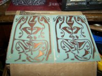
Two circuit boards found in cleanout, in box from SWTP 1973.


Any idea what these are?


I'm thinking these are part of the their Lil Tiger MKII amp kit?


The boards are marked 176a

They were in a box with an assortment of parts from Southwest Technical Products in TX.


I found this catalog online: http://www.wass.net/othermanuals/SWTPC.pdf
I'm thinking the pic on PG 4 looks like it may be built on these boards?

Attachments

  • 176A (1).jpg
    176A (1).jpg
    536.7 KB · Views: 268
  • 176A (2).jpg
    176A (2).jpg
    543.1 KB · Views: 276

HELP KEF CRESCENDO WIRING DIAGRAM NEEDED PLEASE!

Hi everyone ,

I recently got hold of a pair of KEF Crescendo speakers unfortunately they’ve seen better days and they’ve come to me in a bit of a state.
Everything is present as ought to be be but the wiring is in a terrible mess.

None of the drivers or tweeters have had their wiring ripped away thankfully but yeah, the rest of it is a right old rats nest.

I really need a schematic so I can start afresh and rewire these as they should be wired but I cannot find a wiring diagram anywhere and I have searched both on google and in this website.
I searched here both in threads and then in individual posts, I was a bit surprised when I couldn’t find a single mention of these speakers or even KEF !
I don’t understand what I’m doing wrong re searching here.

If anyone can share the schematic or direct me towards one I’ll be most grateful !!!

Output impedance & speaker load - Aleph 30

Hi guys,
I have a question regarding the Aleph 30 amplifier output impedance.
The user manual says that under 8 ohms load can deliver 30 watts and under 4 ohms can deliver 40 watts, but there is no clear information about the output impedance and the minimum load acceptable. Here the question.
Is there any disadvantage/trouble to load the Aleph 30 using a speaker with an almost constant 3 ohms impedance?
I think, for example, temperature issues and/or reduced dynamics performance of the amplifier due to the higher amp current solicitation.
I'm designing (ok, trying to) a high efficiency a speaker (91 dB) using 4 ohm drivers, and the final impedance I can obtain is allways under 4 ohms (see attached). Phase is almost perfect, spl response flat, efficiency goal achieved, but... impedance seems to be maybe too much under the 4 ohms I was planning.
Any advise?
Thanks a lot

Attachments

  • 2 woofer 1 tweeter Project Impedance.png
    2 woofer 1 tweeter Project Impedance.png
    20.4 KB · Views: 164

Help on Heco Cantata 550 tweeter tweak

Hello!

I have a pair of Heco Cantata 550 that came without tweeters. As well i have a pair of Heco Allegro 350. For choice I have a Philips 8 ohm AD11600 tweeter for the cantata but original is 4 ohm. The tweeter could use a little boost so I would have to remove a resistor from the pcb of the XO. WOnder witch one? Thank you! In the pictures the tweeter gets out + and - at top left.

Attachments

  • unnamed.jpg
    unnamed.jpg
    134.6 KB · Views: 119
  • unnamed (1).jpg
    unnamed (1).jpg
    139.2 KB · Views: 117

can someone please advise on a problem with my Luxman tuner?

I have owned a Luxman T110 for about ten years and have had no problems with it until now. It worked fine yesterday afternoon and when I turned it on this morning the panel lamps did not light up. I had not listened to it at this point--I just unplugged it and checked the internal fuses. We had a bad windstorm here last week and our power grid has been unstable since then. One of the .75a internal fuses was blown. I replaced the fuse, powered it up and the panel lights worked again. However, I cannot tune in any station. If I take the muting off and set it to mono I can get some audible reception, but the signal meter does not budge. I use an outdoor antenna and the other stereo receivers in my house get perfectly clear reception. I verified the path of the antenna wiring and tried a smaller indoor antenna in various configurations with very little change and still no visible movement of the signal meter. I should add that I live in the middle of a large metro area and have a clear line of sight from my house to the peak with most of our broadcast antennae. The signals or antenna aren't the issue. The attenuator and de-emphasis controls make little difference. I see no obvious shorting or charring inside the chassis. I downloaded the service manual (attached) and did not find anything that was useful to me there. I lack the equipment to do the alignment procedure.

Can someone please point me in the right direction of what to look for? It seems that troubleshooting info for these tuners is a bit scant online.

Edit: Forgot to attach the doc. This is the site I got it from:

Luxman manuals | Hifi Manuals Free: page 3

Siglent SDG810 has no output overload protection

It did not happen during my almost 40 years as a professional electronics designer but I managed to destroy
a measuring instruments output of a signal generator.
I accidentally touched the output of my only a few months old function/waveform generator, the Siglent SDG810, with a 24V dc supply voltage.
Asked the manufacturer if it is possible to repair this but their response was that the total costs would exceed the cost of the purchase of a new one.
After this had happened I realized that I did not have noticed that the two outputs of that Siglent generator are not having any overload protection at all.
So, yes, not very professional that I did not noticed this before purchasing the generator. The lack of overload protection is not even mentioned in their specs of the generator,
but only at the bottom of the front panel of the generator. So, again, yes I am the only one who is to blame.
Now, my question to this Forum is: Does anybody had this experience before and if so, is it possible to do the repairing myself?

Pretty blue light

Are there any specific brands that produce the best fluorescence? That pretty blue glow from cobalt in the glass. None of my New Sensor’s seem to have any - even at 600 volts on the plate. The most recent tubes I have that do glow are a 1990’s era quad of Svetlana EL34’s, with a B+ as low as 350V. Gets better at higher voltage, of course. I’ve seen a lot of older ones do it over the years. Is it just luck of the draw, or is there some rhyme or reason to it?

Proper KSA-50 bias setting???

With out wading through all 10 gazillion posts in the KSA-50 thread can someone tell me the proper bias setting for a KSA-50 with three sets of OP decvices? I had to repair mine due to a slight DC imbalance that existed... found a pre-driver that was way out of spec. and even the DC balance adjustment could not compensate for it. I replaced both predrivers with a matched pair and now it is spot on again. At the present I am measuring ~360mv across the emitter resistors on both channels. Is this correct, or good enough for now? I normally like to do bias by using the distortion analyzer but moine is not set up at the moment and although that works well for class AB amplifiers the distortion analyzer method may not work as well for this amp...

Thanks!
Mark

Pioneer KEX-900 8-pin DIN AUX to 3,5mm audio jack.

Hello all. So I would like to connect a bluetooth reveiver to my KEX-900 head unit. The unit does have a AUX-In connection for the CD-player component on the back, but it's a 8-pin DIN plug, so I would need an adapter. I'm no electrician, so I could use some help figuring out the wiring. I assume that the 3.5mm connector only has three wires (left channel, right channel and ground) so is it as simple as connecting those to the right pins on the DIN plug? I have found some scematics, but I'm not sure if they are the correct ones or if I'm reading them correctly (link under the post). Is the correct wiring order left channel to pin 3 (middle on the left of the plug), right channel to pin 6 (lowest pin on the left) and ground to pin 5 (top pin on the left)? Do I need anything else?
There seems to be some ready made adapters for sale on ebay, but they are meant for Alpine headunits. Would these work on Pioneer, or is the wiring different?

Pioneer servicemanuals for Centrate black series

Has anyone built the "Jenzen Illuminator"

As the title says.

I am looking to see if anyone has built this design and if so was it worth it? What other DIY speakers are in the same realm? I have seen the "Elsinore" and have considered that design for over a year. However, I like the Illuminator because it is not like his other designs using odd hard to get drivers like the Janzen tweeters or the Elsinore that also requries special waveguides to be made.

I am looking for more opinions on the sound of the Illuminator design and if there are any other plans that I might look at.

James

Hey there

new beginner

hey guys its shawn, young bloke from australia who has taken a new interest in sound systems and recently bought myself 4 JBL J-Bins and 4 JBL trap cabs both empty shells which i am really excited in to learning how to build these into prime speakers lot of work to do, very new to all of this stuff and looking forward to learning heaps!!!😀😀😀

Recommendation for a good mid range driver for vocal

I just completed my first project with a 2 way bookshelf speaker using the Tang Band W6-1721 6-1/2" Underhung Midbass Driver and the HiVi RT1.3WE Isodynamic Tweeter. The crossover is around 2.3kHz.

The bass is pretty impressive coming from a 6.5" woofer and if the listening room is not big, you can actually do without a sub-woofer. The high coming from the HiVi is pretty accurate and detail, good for instrumental music. However I find the mid range is somehow lacking, especially in term of vocal. The vocal sounded lay back, not warm sounding and does not have that "thick" texture.

Now I am trying to add on a mid range driver on top of my bookshelf speaker to enhance the vocal section. I would really appreciate if someone can recommend me a good mid range driver that can produce sweet, warm, "thick" and slightly forward sounding vocal. And at the same time not too bright or harsh. Looks forward to your kind recommendation, TIA.

Edit : Of course, I will be redoing my crossover design with the new recommended mid range driver.

Thorens TD 125 Tonearm Rewire - Balanced or Single-ended?

Looking for some input on a project I am working on. I know this topic has been discussed elsewhere on the forms, I have dredged the archives of diyAudio for answers, but have not found anything definitive, so here I am.

I am working on a new vinyl setup with two projects being worked on simultaneously.

I am designing a from-scratch MC phono stage, using Lundahl LL9226XL step-up transformers, triode-strapped D3a for the first gain stage, passive "all-in-one" RIAA EQ, triode-strapped EF86 for the second gain stage, and FET source follower output buffer.

The second project is a restoration of a vintage Thorens TD 125 MKII turntable. I am rewiring the tonearm.

I have the opportunity here to wire the tonearm for a balanced output and the phono stage SUT for a balanced input, I am trying to determine if it is beneficial to do so.

While common-mode noise rejection on the balanced wiring will be increased, the noise contribution from each signal wire will be increased, seems to controversial whether or not it is a sound design decision.

For those experienced using both connections, what have been your findings? Thanks.

Test amp

I'm looking for a test amplifier for the home workshop.
Can anyone suggest a simple cheap clean amplifier sutible for speaker measurements.. The generic China amp I have is well....horrible.
I get decent results with a crude setup through my main setup so I just need a simple dedicated amp of around 20w. Would Even a car (12v) amp do.
Suggestions?

Thanks
Projects by fanatics, for fanatics
Get answers and advice for everyone wanting to learn the art of audio.
Join the Community
507,833
Members
7,890,142
Messages

Filter

Forum Statistics

Threads
406,340
Messages
7,890,142
Members
507,833
Latest member
GaDysh