I'm looking for a test amplifier for the home workshop.
Can anyone suggest a simple cheap clean amplifier sutible for speaker measurements.. The generic China amp I have is well....horrible.
I get decent results with a crude setup through my main setup so I just need a simple dedicated amp of around 20w. Would Even a car (12v) amp do.
Suggestions?
Thanks
I would suggest a simple chip amp (LM1875 etc) would be the easiest and most suitable. There are zillions around, ready built and diy options.
Same here: LM1875, 20W, suitable for 8 ohm loads or LM3886, 50/60W, drives 4 ohms so it´s more versatile.
Avoid car amp, they are very often bridged, that turn measurement to be complex if not impossible without specific device such as differential probe.
A standard measurement setup with ARTA (with an ARTABOX) is not compatible with a bridged amp.
Go chip amp as recommanded. I've built my sort of ARTABOX with two ALI sourced TDA2050, a boost switching converter powered by a Thinkpad power brick....very far from hifi but ok to setup and tune the crossover of speakers.
Last edited:
A single supply chip amp (with an output coupling capacitor) would protect the speakers
from high DC output voltage, in the event of amplifier failure.
from high DC output voltage, in the event of amplifier failure.
Very true but just in this particular case of speaker measurement duty, I guess direct coupling (split supply) would be better to avoid capacitor interacting with speaker and measuring jig.
A lot of measurements will be made at the lowest frequencies, including resonance and below.
A lot of measurements will be made at the lowest frequencies, including resonance and below.
I have started a project based on the LM3886.
because changes usually get made along the way I decided to just build a prototype based on the application notes in the datasheet.
I have run into a problem and was hoping for a little insight here since I usually get around 30min of continuous hobby time at any sitting.
Full disclosure, my first mistake was a miswired capacitor which resulted in a poped capacitor and running the chip on single supply! ooops
next i noticed i wired the input incorrectly.... oops I noticed my volume control was a bit wanky and noisy.
So the current issue:
At low volume every thing seems fine, but at mid volume it becomes noisy only to fall quiet again at high levels.
Any tips as to why?
I have a question as well;
In the guides i have read it is said you must balance the bias currents in the pos and neg terminals. to do that you make Rf and Rin equal.
But... if i use volume pot at the input (eg. close to Rf) doesn't that get thrown out the window?
What is the right way to have volume control AND proper bias?
lastly it seems my amp now cuts mids and vocals completely out! Have a fried my LM3886?
I have learned over the years to take great care building up electronic assemblies.
Any mistakes can blow components which makes fixing it harder.
Go through the circuit diagram and double check everything.
Then check wiring.
Put your current circuit on here and we will take a look for you.
Any mistakes can blow components which makes fixing it harder.
Go through the circuit diagram and double check everything.
Then check wiring.
Put your current circuit on here and we will take a look for you.
I know what I'm doing around electronics/circuits.
As said. Sometimes I maybe rushed to make some progress. Although I'm am usually careful with attention to detail.
The circuit is that in the datasheet without optional components.
My transformer, PSU is 75W, +(-)26.2 Vdc with 8mF in total.
I have looked it over and do not yet see any mistakes, which of course does not mean it is without. As such I guess I have somewhere along the line fried the chip.
When I build stuff up I read the part value off the parts list twice.
I check component reference and value twice.
And I have been doing it for 40 years.
Its easier to be more careful up front and take your time than to spend hours pouring over a dead amp.
More haste, less speed.
Have you checked voltages around chip amp ?
Do they make sense.
If its blown they are fun to get out. I cut legs up near chip amp body to leave long legs.
This gives something to tug on with long nose pliers while you heat the pin at the pcb end.
I've only been doing this stuff for 20 years.
Don't take this the wrong way, I'm not looking for skill improvement/advice,
Just insight from other with more familiarity with this or similar chip amps and their fault symptoms etc. Just to get a heads up when I get a few minutes to work on it.
I believe my chip is toast and don't look forward to removing it from the circuit. I hope for a little wisdom to treasure myself I hove not overlooked any thing. I will destroy it to get it out quick n easy in any case.
I do appreciate any suggestion.
When I build stuff up I read the part value off the parts list twice.
I did it at least three times and at least once on a later occasion.
Have you checked voltages around chip amp ?
Do they make sense.
I checked all the voltages. Every thing is just right.
I cut legs up near chip amp body to leave long legs.
This gives something to tug on with long nose pliers while you heat the pin at the pcb end.
I do the same unless I have access to a nice pro desolder station. Even then it is often easier
Attachments
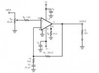
The data sheet circuit unfortunately is not complete enough to make a successful amp, its more a test circuit.
Try adding a small inductor in series to the speaker (just a few turns of wire that are air spaced, no magnetic former) and also add a Zobel network directly across the output of the chip to ground. Use a 6.8 or 10 ohm resistor and a 0.1uF film cap connected in series.
Also be sure to return the speaker ground wire back to the power supply to avoid any possibility of feedback due to your layout.
The input arrangement isn't great either. Ideally the wiper of the pot should be AC coupled to the input pin and the input pin connected to ground via a 20k resistor (to equal the feedback resistor value).
Reading your diagnostics, it appears a tendency to oscillate depending on the position of the wiper.
As noted above, use a series R between wiper and input of say 1k, (that's Rb) and a small cap, like 1nF from that 1k to ground, on the input side.
You may need to have another 1k stopper between the top of that cap and the actual chip input pin.
And the DC path to ground of 20k of course.
Jan
As noted above, use a series R between wiper and input of say 1k, (that's Rb) and a small cap, like 1nF from that 1k to ground, on the input side.
You may need to have another 1k stopper between the top of that cap and the actual chip input pin.
And the DC path to ground of 20k of course.
Jan
Last edited:
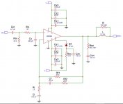
This is a typical generic circuit. You can leave your mute pin as it is.
Note the coil and Zobel network.
The input section is correct here. Your volume control wiper would go to the cap marked Cin.
This design also has a little network across the feedback resistor to aid stability.
Note the coil and Zobel network.
The input section is correct here. Your volume control wiper would go to the cap marked Cin.
This design also has a little network across the feedback resistor to aid stability.
Attachments
- Home
- Amplifiers
- Solid State
- Test amp