After my last experience with relatively high power SET amplifier (see
https://www.diyaudio.com/forums/tubes-valves/327637-lian-845-set-kit-commercial-product.html ), I started thinking about upping the game and getting into power range comparable with push-pull tube amplifiers. There are two ways get there — either use high power tube like 833 or using tube in A2 class where grid gets positive in relation with cathode.
Tubes like 833 require even higher voltages than 845 or 211 and very high output impedance requires extraordinary effort to make output transformer compatible with it and still have enough bandwidth for full range audio. That will result in very expensive design, with a lot of full custom components. Example of that approach is WAVAC 833. But for the $350K price results (
Wavac SH-833 monoblock power amplifier Measurements | Stereophile.com ) are not very impressive.
A2 class though can allow lower plate voltages with higher current, thus reducing requirements to power supply and transformer design. Load impedance 4-6K ohms is very much achievable without extraordinary effort. With output tube operating with grid current you need to have low impedance driver circuit. Easiest way to achieve that is using cathode follower with direct connection to grid of output tube. It is possible to use 845 or 211 tube that way, but there are also other tubes which were design to have grid current almost at all signal levels. One of examples is 805/838 tube. The only real difference between them is that original 805 had a plate cup, and 838 did not. Today China makes 838 equivalent, which for some reason they call 805. Thus when you buy a new production 805 tube, you are getting 838. Of cause neither of these tubes is really affordable as NOS — they almost all gone and were not manufactured outside of China for decades.
I didn’t want to do build from scratch and just like with 845 based amplifier I referenced above, I decided to get a modern Chinese amplifier and start from there. Line Magnetics is a mid-range Chinese brand which builds and markets tube amplifiers all over the world. They have amplifier based on 805 tube which is claimed to reach 48W of output power. Price (if you buy direct from China) is in relatively affordable range, even when one account for international shipping charges. And finally I made a move and placed on line order.
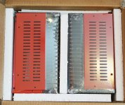
After 3 weeks of waiting UPS guy knock on my door, and when I opened it, large cartoon box was sitting next to it. The box has some signs of tear, which is explainable (it“s path was from mainland China to Honk Kong, to Japan, to Chicago and finally to Dallas). But when I opened it — everything inside was in pristine shape. Tripple boxing and attention to packing details did the job.
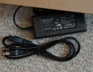
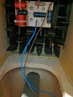
One note — when you buy direct from China, you likely getting the version that requires 220 volts power line. Some devices can be modified to use 120V, some are not. From what I read about Line Magnetics gear, I thought that I will be able to easily convert it with s bit of soldering around power transformer. But I also had a boost transformer, which I purchased many years ago, but never put in service. Thus I was ready to use amplifier out of the box too. As alternative, you can arrange 240V outlet in you music room — many audiophiles have it already. If you do not, getting step up transformer is much cheaper than hiring electrician. In the end I found that my version of amplifier (made some time in late 2019) does not allows easy voltage change, and I kept it running with boost transformer. But to use in my high-endish music room I bout another transformer, which simply looks more in place (UMI Step UP 110 to 220 Voltage Converter found on Amazon). It is rated for 1200VA which is well enough for amplifier that consumes 500W.
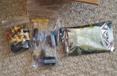
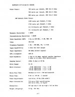
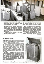
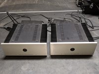
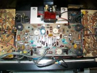
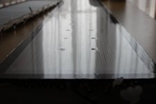
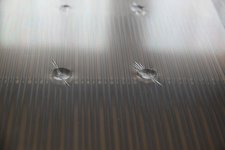
Line Magnetic LM-508ia has excellent fit and finish. Designers had clear attention to details and manufacturing quality was excellent. All chassis is covered with mirror like enamel probably ½ mm thick. Connectors for inputs and speaker outputs are of high quality. Amplifier came with pair of Line Magnetic branded Chinese 805 tubes, pair of also LM branded 300B tubes (used as drivers), pair of new production Electro-Harmonic 6SN7made in Russia, and a Chinese 6N9P (equivalent of 6SL7) tube of unknown brand. Later we will see that this amplifier works best with tubes that came with it from the factory.
LM-508ia has two adjustments — output tube current and hum balancing. When I turned it on, both of these adjustments were spot on. It only can be explained if each unit is tested and adjusted right before it is packed into the box.
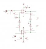
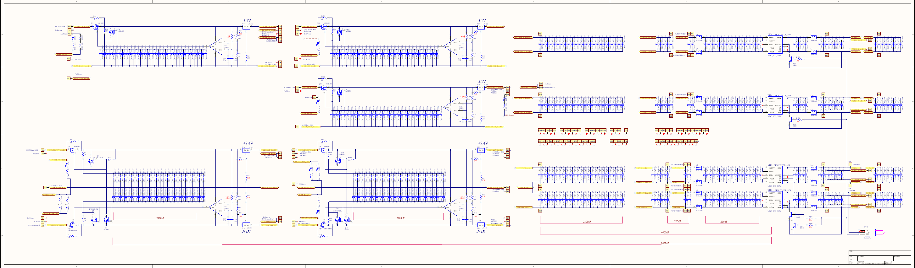
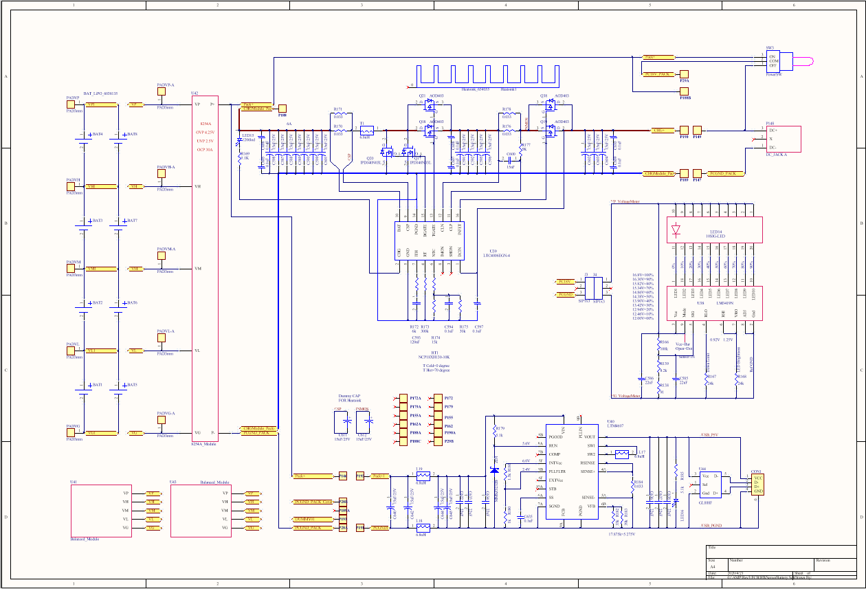
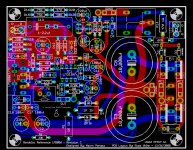
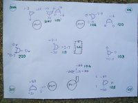
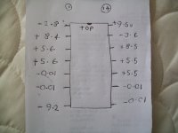
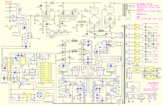
This amplifier has simple classic circuit (see Pic.1) : there are two stages of amplification which are classic resistor amplifiers with half of 6SL7 and paralleled 6SN7, loaded with 300B as cathode follower directly connected to grid of 805 tube. The latter has relatively low plate voltage, and grid is positive at idle. 300B operates with negative cathode source and idle current at about 40mA, while output tube is biased to 120mA of plate current. All that results in constant power consumption of about 500W. Power consumption does not change while you play music — this amplifier really operates in A class. Al power sources use solid state rectification and CLC filtering. Circuit includes timer that delays high voltage until all tubes are warmed up. Additional digital circuit is used for remotely controlled volume pot. I used this unit as pure power amplifier and thus remote control was put back in the box until I decide to sell it.
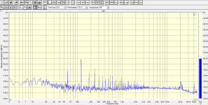
LM-508ia has three regular inputs, which can be selected with front switch and affected by volume control, and fourth input that bypasses volume pot and designed for use with per-amplifier. Unfortunately the circuit does not change and all gain stages are used in either case. Thus the only advantage of using fourth input — it ignores volume control setting. But noise/him level stays the same regardless of which input you use. Like almost all tube amplifier, this unit has some hiss and noise at the output which can be heard through speakers when you are close to them (my reference solid state Bryston is dead quiet in comparison), but I didn’t hear any hum from my sitting position 8 feet away. I measured AC noise at speaker and it was below 2mV. Main type of noise is random hiss and some hum like sound from 60Hz power line frequency and its harmonics. Pic.2 shows spectrum of noise as it was measured by me.
Before putting amplifier on my workbench, I decided to play few records with it. The result was generally positive. It plays loud enough through my 89db/W speakers without obvious signs of clipping. Overall sound was something between my 845 based amplifier (it was not as soft) and solid state Bryston (LM still played like tube amplifier). There is one more setting switch available — it adjust amount of global negative feedback to listener“s liking. Unlike A1 class amplifiers, this amplifier needs some amount of negative feedback to reduce distortion and output impedance to make it compatible with modern speakers using complex crossovers. I initially use 8 ohm output and least amount of feedback (almost none), but bass was uncontrollable. Increasing feedback to second position improved sound significantly. I also tried to use 4 ohm outputs and like it more. In the end the best for my speakers was 4 ohm output and second setting of feedback. When I tried to increase feedback, bass became even tighter, but overall sound stage started collapse. It is clear why variable feedback feature was included — make amplifier work best with various speakers.
>>>see follow up below<<<


 Moderators Note: The title of this thread was changed around the time of post #36, from "bass reflex sucks", as it didn't convey the topic well enough according to e3k.
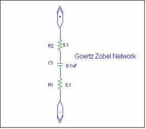


