CSS EL70eN

I have four matched EnABLed drivers. They are new and unused. I had built a pair of micro towers for a member some years ago and was so impressed with the sound I grabbed these for myself. I’ve come to realize I will never use them.

$300.00 usd plus shipping for all four.

Attachments

  • 646DE7CE-CE96-40BD-A907-8B14A3C12BD2.jpg
    646DE7CE-CE96-40BD-A907-8B14A3C12BD2.jpg
    933.5 KB · Views: 427
  • DE0EB3A5-325C-43F2-846D-871F0EF8CF76.jpg
    DE0EB3A5-325C-43F2-846D-871F0EF8CF76.jpg
    847 KB · Views: 388
  • 010090E7-280D-4694-9E25-6F5E3328E4FC.jpg
    010090E7-280D-4694-9E25-6F5E3328E4FC.jpg
    779.6 KB · Views: 396
  • B88A7B67-476E-47FB-9508-B58C3D964881.jpg
    B88A7B67-476E-47FB-9508-B58C3D964881.jpg
    883.3 KB · Views: 383

Streaming System /w Active Crossovers

I've been thinking about my next new big stereo and some of the challenges of integrating the best of the digital streaming and analog worlds. Some general wants:

1. Linkwitz LXMini /w subs or LX521
2. Active digital crossovers using high quality DACs and Hypex/Purifi Amps
3. Good streaming single-board computer, performing crossover computations and sending to external USB DACs.
4. Good support for analog sources, tube buffers, headphones

Challenges:

a. Computational overhead for high quality crossovers may affect DSD to PCM conversion and/or continuous delivery of streaming content to DACs.
b. Analog integration in a heavily digital system where analog only occurs just before Amps.
c. Cost and complexity of multiple high quality DAC outputs, resampling audio and timing.

One possible solution I've considered:

- Use a $99 NVidia Jetson SBC to stream audio using something like Moode Audio, then create an ALSA sound plugin to perform Linkwitz filtering using cuSignal and builtin CUDA hardware acceleration. Stream the filtered audio channels to a high quality external audio interface. (note 1)

- Use a studio grade audio interface like a Motu 8a to convert 4 - 8 channels of tightly synchronized and filtered streaming digital audio to the driver amps.
- Use the analog I/O on the Motu to support turn tables, tube buffers, headphone amps.
- You get extreme recording, mixing and parametric EQ for free.
- You get audio over ethernet (AVB) for free.
- You get a cool display for free.
- All at the cost of about $100 per DAC output channel, which is well within the DAC budget for audiophile-wannabe consumer DACs on the market. Why buy ChiFi, when studio grade pro-level equipment is so affordable? No offense to friends at Schiit.

Anyway, constructive comments most welcome.

Note 1: I'm a linux systems software engineer, so if the basic tools are available I'm pretty sure I can do this. It will take a little bit of signal processing theory / crossover theory research.

For sale. 3 phase BLDC motor kit for turntable.

I've built several generations of this controller/motor combination, the latest using a BLWS series motor and the PSU/amp in one enclosure. The OP of this thread was the first iteration and it used a BLWR series motor and the PSU split into 2pcs: one for the controller and one for the amp. I no longer have need for this version, so I'd like to offer it for sale.

The kit includes:
One Condor controller Rev A (housed in an Eagle extrusion)
One 25W 3 channel amp based on the TI3123 class D amp
One AA BLWR172S-24V-2000 BLDC motor with 600 RPM pulley and aluminum stand-alone motor housing
One 24VDC 1A wall adapter (not shown in pic)
All cables and connectors needed for operation.
The PSU is capable of 33/45/78 RPM with the included single pulley, CW or CCW rotation (belt or idler) and reduced voltage after start up. It will also accept feedback from a RR tach or DIY Arduino tach.

$300 PayPal Continental US only please. PM me if interested.

The picture shows the actual components. The controller is production quality, but the amp section is a hand built prototype, so it is a little rough on cosmetics, but it is usually placed out of sight anyway.

Attachments

  • DSCN1544.JPG
    DSCN1544.JPG
    281.4 KB · Views: 561

Driver Bootstrapping Explained with Graphical Help

Altho this topology does appear to be positive feedback & increases stage gain slightly it does not qualify as feedback in the usual sense. Feedback over a single stage needs to go back to a cathode or grid where some gain can be realized. Back to the plate there is no gain possible.
The driver tube used in this example is a 6SN7GT, a very common hookup. The load resister is 27K powered by 400 Volts B+. So the center red line is a 27K loadline terminated on the 400 volt point on the 6SN7GT plate family of curves.
The bootstrap connexion inserts some signal into the power supply B+ in the same phase as the main signal. That results in a higher impedance loadline & more gain occurs. But the increase in gain is small, the driver is usually a triode.
The other red lines are the same slope as the 27K loadline but they terminate at the limits set by the boot strap signal. A new loadline shewn in green is the result. This loadline looks like ~42K, (500 / 11.8)K. Calculating gain for the 27K loadline & assuming rp to be 7.7K & mu of 20 the gain is 15.56. With the 42K loadline the gain becomes 16.90.
The difference is 20 log (16.90/15.56) db or 0.72 db. Not much at all! I measured the difference of gain with & without bootstrapping on my version of Norman Crowhurst's Twin Coupled Amplifier. It was ~1,5 db.
The real benefit of bootstrapping is the longer loadline available to drive the following stage. Taking the extremes of the possible signal excursions from the control grid at zero volts at one end & -20 volts at the other looks like the 27K loadline would be OK at 280 volts peak to peak. For the bootstrapped 42K loadine the same measurement looks like 318 volts peak to peak.
In a practical circuit the boot strap signal would be much larger than in this example. But the 6SN7 curves don't go to a high enough voltage to shew that here.

Attachments

  • 6SN7GT Plate Family Z3 with Boot Strap Limits & LoadLines.jpg
    6SN7GT Plate Family Z3 with Boot Strap Limits & LoadLines.jpg
    221.4 KB · Views: 211

Vox AC4C1 has very low output

Hey friends,

I'm working on a friend's AC4C1, and it's been driving me crazy. It works and sounds good, it's just noticeably quieter than it should be.

This is the schematic I've been using, although the B+ wiring is shown incorrectly. V1A is B+4, V1B and V2A are B+3, V2B is B+2.
index.php


I've replaced the tubes, measured all the voltages, checked ESR and capacitance and resistances, and tried swapping the EL84 bias resistor.

I've run through the circuit with an oscilloscope and tone generator, and the waveform looks pretty gnarly coming out of V1 but not too bad coming out of V2.

It's a super simple amp so it shouldn't be that hard, but I'm not sure what to do next. One other thing is there's a small burn in the jacket of the wire connecting the OT to EL84 pin 7 and it appears to have made contact with the clip that holds the tube in, effectively shorting B+ to ground. Would this potentially affect the OT?

Any ideas for troubleshooting?

Thanks

Portable Bluetooth Speaker Design Help

Hi all,

I'm designing my first speaker - a portable bluetooth speaker which I plan to 3D print the case for...

I'm currently at the stage of designing the box and selecting the drivers etc.

I'm using WinISD to model this - so far I'm struggling to meet my original goal of around 60Hz F3 with 1L of box volume.

I think I'm pretty close to having a workable plan now - however I'd really appreciate someone else more exprianced than myself looking over the charts / figures and giving some feedback on if this will be good or if / what I should change etc!

I'm using 2x Dayton ND65-4 2-1/2" full range drivers, paired with 2x Dayton ND105-PR 4" Passive Radiatiors (with 21.8g weight added to each) with a box volume of 1L (0.035 ft3).

I'll attach screenshots of the transfer function chart - it shows an F3 of 83Hz and a bass boost of 2.5db above 0db, which I 'belive' is desirable in this type of design?

The main concern I have is cone excurtion - the amp I plan to use is the xyp15w - which claims 16w per speaker at 12v - so I'm modeling this with a total input of 30w as a worst case senorio - at this, I'm seeing up to 2mm over xmax between 98Hz and 170Hz - the passive radiators are well below xmax however.


As above, I'd really appreciate any advice / tips / comments on this plan!

Many Thanks,
Jack

Transfer Function Chart:
Transfer Function Chart.png

SPL:
SPL.png

Cone Excurtion:
Cone Excurtion.png

Passive Radiator Excurtion:
Passive Radiator Excurtion .png

Semi Non-Switching Output Stage of LM3886 Clone

At first glance the output looks to be quasi complimentary but it isn't. The diode feedback is a game changer in this story, as the scope graph shows the upper output never cuts off.
attachment.php

At this stage it is in open loop with a gain of 60db 20khz F3 with a distortion of 0.13% at 30Vp 10khz, and decreases with lower powers keeping even order dominant.
Hayk

Attachments

  • lm3886 clone.JPG
    lm3886 clone.JPG
    69.4 KB · Views: 1,511
  • lm3886 clone2.JPG
    lm3886 clone2.JPG
    46.5 KB · Views: 672

What drivers for 3-way + sub in 180liter housing?

Hello Friends!

I'm writing this to ask your kind opinion and guidance for my new speaker build project, particularly what drivers (and crossovers) would be suitable.

Budget is a concern - no more than $500 the lot would be ideal.

What cost effective solution is there for choice of drivers that play well together for ~180 liter large housing?

Background:

I've "built" a few speakers, but nothing fancy:

The first one was to shoehorn some Polk ceiling speakers into a formerly GLL imagio box. The should quality improved massively, which was a nice result.

The second one was to build a sealed box around a $25 JBL GT5-12, which was just too easy, and it also sounds good.

The third was to build a concrete housing for a couple Avalance woofers I had lying around. This was more a proof of concept that didn't pass the wife acceptance test, and it doesn't sound great either because the Avalanches like free air installation.

The next one is where I need your advice. I found some cardboard tubes (three of them) which are 950mm tall with an internal diameter of 505mm. Wall thickness is about 20mm. They are absolutely solid, and I now want to put a big fat sub in one of the tubes, and use the other two as 3-way mains.

I've uploaded some pictures, give you some idea.

I'm using a 2 x 75W class D amp to drive my current mains and a 310w class D for the sub. I'd like to play with DSP, though never been involved with that. Due to kids i've been out of the hifi scene for 12 years. I guess I missed quite a bit!

Oh, and I'm in Australia, and Parts Express charge a pretty penny to ship here 🙁

Thanks!
Phil

Also: I'm totally not adverse to some funky configs, like putting a whole ring of speakers around the cylinders for omnidirectional speakers.

Attachments

  • IMG_8737 (2).jpg
    IMG_8737 (2).jpg
    788.1 KB · Views: 187
  • IMG_8739 (2).jpg
    IMG_8739 (2).jpg
    922.7 KB · Views: 182
  • IMG_8741 (2).jpg
    IMG_8741 (2).jpg
    424.8 KB · Views: 175
  • IMG_8740 (2).jpg
    IMG_8740 (2).jpg
    368.5 KB · Views: 164

Conversion of a GEC radio 1947

Hello all
Loudspeaker advice.
I'm converting a GEC radio into bluetooth speaker using the cabinet.
Will be stereo. max 50w/channel @ 4ohms
There are two panels where each speaker or combination (woofer/tweeter) will fit. Size of these panels are 9" high x 10" deep
I want the best sound possible; not interested in bass heavy bull full range.
There was an 8" speaker in there as shown on photos. Cabinet is all wood and I will be making it more rigid.
Any thoughts or recommendations about single speakers or pairs with crossovers and suggestions for make. ? thanks Tom
Screenshot 2020-10-07 at 16.17.17.jpg

FS: pair of speaker cabinets for mini monitor.

Hello. I have a pair of cabinets professionally build that I’m not going to use. I have changed my project.

Built in MDF 19mm
Tweeter cut is 104mm and woofer cut is 150mm.

Dimensions: 18cm Wide, 30cm height, 24 cm deep.
About 8 litres.

I’m asking 60€ Much less than they cost.
Shipping will be 25 to 30 euro for most EU countries.


An externally hosted image should be here but it was not working when we last tested it.

An externally hosted image should be here but it was not working when we last tested it.

An externally hosted image should be here but it was not working when we last tested it.

An externally hosted image should be here but it was not working when we last tested it.

An externally hosted image should be here but it was not working when we last tested it.

An externally hosted image should be here but it was not working when we last tested it.

Scan-Speak Discovery 10F/4424G / 10F/8424G

Scanspeak Discovery 10F/4424G, 4" Midrange 4 ohm: Madisound Speaker Store
Scanspeak Discovery 10F/8424G 4" Midrange 8 ohm: Madisound Speaker Store

The price is a big turn off. I could have sworn these were around $60 each when I first saw them. Did the neodymium really go up so fast, or was I just dreaming? I sure wish they were cheaper. Why keep using neodymium if it drives cost up so much? On the other hand, the one thing I always want more of with 3" drivers is motor strength.

Cost aside, I thought the results on Krutke's blog looked pretty promising. Looking at Sd, they're really about a 3.5" driver. Has anyone tried these as full-range? Any thoughts on the "coated NRSC fibre glass cone"?

Allnic H3000 phono stage help with fault please

Hello people. My brother has an Allnic H3000 phono stage that has just given a fault. It 'isn't receiving current to either the left or right outputs'. The psu would appear to be working
It has some current meters on the front and they are both low/zero. He said if it was a valve going down it would show on these....not sure what that means.

Does anyone have experience of these things....a schematic.....know a good service tech that could look it over?...or indeed where to start checking things.
I don't know much about vinyl set ups....I asked if it could be that isn't getting a signal from the turntable to which he replied that may point to a faulty cartridge and that that is unlikely....but I'm guessing it could be wiring in between an issue too maybe?

Any advice appreciated ��

Driver decoupling

We all know isolating the speaker from the ground is better than coupling (spiking) them to the ground. Better LF definition and transients etc. (Sorry if I triggered someone with that statement). Anyhow, what about isolating drivers from eachother? If you have a multi way speaker, the driver playing the lower frequencies to the next will play that drivers fs, and then make the higher frequency driver essentially work as a tuned mass with a diaphragm, creating distortion. If the baffle is devided for each individual driver, and separated with Taica alpha gel, the baffle/enclosure borne vibrations will be redused by some 20 - 30 dB (-ish). Of course parameters like internal baffle material damping, distances and geometry will be of importance as well. I've seen Q acoustics and B&W with damped tweeter mounts, so I suppose the damping must have some quantifiable benefit. Have you tried/experienced it, or have any thoughts on the matter?

TDA7492 vs TPA3116 Tests

Has anyone purchased this item?:
http://www.ebay.com/itm/360982220650?_trksid=p2059210.m2749.l2649&ssPageName=STRK%3AMEBIDX%3AIT#ht_3500wt_1111

I purchased it and am disappointed in results obtained in testing. I used a 24 volt power supply, 6 ohm resistive load, and 1kHz sine wave input signal. The most voltage I could get out before clipping was 11.5 volts. This translates to only 22 watts.

I pulled the heatsink and right beside the chip the silk screen says TDA7498. However, the chip must actually be a TDA7492 chip. If I increase the power supply voltage to 29 volts the chip goes into shut down. This is the shut down voltage for the TDA7492 part.

I have this board from Parts Express:
http://www.parts-express.com/2x50w-tda7492-class-d-amplifier-board--320-301

With the same test conditions listed above, I can get 14.3 volts out before the amplifier goes into clipping. This translates to 34 watts which is much better than the board above.

As a comparison, I have this board:
http://www.ebay.com/itm/DC18V-24V-TPA3116-ClassD-Amplifier-Board-50W-50W-Filter-Capacitor-2-10000UF-/251413946728?pt=LH_DefaultDomain_0&hash=item3a89706168#ht_2780wt_1291

With the same test conditions, I can get 15 volts out before the amplifier goes into clipping. This translates to 37.5 watts which closely matches the power out versus power supply voltage curves for the TPA3116 part.

In all tests, I am only driving one channel. And I let the resistive load cool down between tests.

I have two questions:
1) Any guess as to why the first board will only put out 22 watts and the second board with the same part will put out 34 watts?
2) Is the TPA3116 part much better than the TDA7492 part? It will put out almost 3 extra watts under the same test conditions.

PCB layout of Bill Christie's Phono Preamplifier

I made a PCB layout of Bill Christie's Phono Preamplifier. The original article can be found at

You Can DIY! Build an External Phono Preamplifier | audioXpress

https://audioxpress.com/assets/upload/files/BillChristieExternalPhonoPreampAXJul2013.pdf

The changes made are as follows. The LME49740, which is not available anymore, has been replaced with two LM4562 op amps. 22 pF Miller capacitors are placed to stabilize the LM4562 from oscillation. The signal grounds for the two channels are isolated from the power ground by hum breaker resistors.


You can find the PCB in the github project


GitHub - profdc9/PhonoPreAmp: A Phono Preamp Based on Bill Christie's design


Enjoy, Dan

Attachments

Rebuilding an old Philco 89

I'm posting a build I just finished. I wanted to do something different from anything I've done before, so my choices may seem a bit...unconventional.

I have a friend who's a historian and into the 1930s and 1940s. I had gifted him an old console radio years ago, but movers destroyed it. I've been keeping an eye out for something to replace it.
I found a Philco 89 on the 'bay. I think the old cathedral radios are some of the nicest designs from that era. The one I picked up has a cabinet in great shape - no discolorations, no missing/broken wood. A light sanding and a few coats of lacquer later and the cabinet is sorted.
The radio on the other hand...
Someone had previously removed the tuning circuitry, tubes, and speaker. Since the radio couldn't go back to original, I decided to bring it up to modern utility. The insulation on the power transformer was dangerously crumbling, the resistors and capacitors were well past their useful life, and the tube sockets were baked.
I started by stripping the chassis and giving it a coat of "hammered metalic" paint.
For the speakers, I had an old University 8" full range that I inherited from my grandfather. I paired that with a Dayton 3/4" Neo and a series crossover at 3000 Hz. The speakers were mounted on a 3/4" plywood subframe that was covered with speaker cloth and mounted inside the cabinet.

Attachments

  • 20200923_095727.jpg
    20200923_095727.jpg
    804.5 KB · Views: 365
  • 20200923_100026.jpg
    20200923_100026.jpg
    914.9 KB · Views: 259
  • 20200922_224455.jpg
    20200922_224455.jpg
    949.6 KB · Views: 286
  • 20200922_224512.jpg
    20200922_224512.jpg
    1,003.5 KB · Views: 263
  • 20200919_111813.jpg
    20200919_111813.jpg
    775.9 KB · Views: 276

Calculating cabinet volume - am I doing something wrong?

I am building a cabinet for these but am a little surprised that the calculated volume I get after I have run the numbers through several different calculators is so low (11-12l). Some give me dimensions that won't even encompass the length of the port that it needs. Am I missing something?

IMG Stageline SP-10/150PA
Technical Specification

Impedance (Z) 8ohm
Resonant frequency (fs) 60Hz
Max. frequency range f3-5,000Hz
Music power 300WMAX
Power rating (P) 150WRMS
SPL (1W/1m) 98dB
Suspension compl. (Cms) 0.19mm/N
Moving mass (Mms) 38g
Mech. Q factor (Qms) 5.36
Electr. Q factor (Qes) 0.30
Total Q factor (Qts) 0.29
Equivalent volume (Vas) 34 l
DC resistance (Re) 6.9ohm
Force factor (BxL) 18.2Tm
Voice coil induct. (Le) 0.94mH
Voice coil diameter 65mm
Voice coil former Kapton
Linear excursion (XMAX) ±4mm
Eff. cone area (Sd) 350cm2

DIY shielding for wires

Hello all, I'm also a member of Lencoheaven where I bought a DIY amp kit sold in the traders section. I think it was developed by Aniket and offered by Sachu 888," Discrete Dynamics amp and pre-amp.After my build was completed Aniket suggested I change certain wires and use shielded wire.
Early in the build prior to any wire purchases I queried the need for shielded wire , wire gauge, silver or copper, solid or stranded. With no definitive answers I carried on.
I'm really very happy with the amp, the pre -amp has an issue with the vol. pot. so I have ordered a new one as per Sachins recommendation, I have given the pot a spray with contact cleaner and this did help in the short run, did not last.
Since I have to pull the Amp pcb to access the pre-amp I thought I would put shielding on any wire that needs it at this time. Don't want to replace wiring as I purchased quality solid core silver wire for hook up, just some basic guidance needed as I don't want do it twice.
Since this is my first post I'm not sure how to post pictures (can I?) to clarify things. Guess I can...cheers frothy

Attachments

  • IMG_2436.jpg
    IMG_2436.jpg
    632.3 KB · Views: 297
  • IMG_2435.jpg
    IMG_2435.jpg
    622.7 KB · Views: 263
  • IMG_2434.jpg
    IMG_2434.jpg
    689.4 KB · Views: 278
  • IMG_2602.jpg
    IMG_2602.jpg
    760 KB · Views: 264

Problem? Bare post in "Memorandum'

https://www.diyaudio.com/forums/in-memoriam/362277-welfare-check-jack-elliano-electra-print.html

This post comes up bare, little formatting or borders, links, reply options.

Is that how it is supposed to be, or has the software dropped a bolt?

Since browsers and themes vary, I attach screen-grabs.

Attachments

  • odd-post-42.gif
    odd-post-42.gif
    116.2 KB · Views: 104

Pass Aleph P 1.7 with Classè Dr8

How do you use this combination?
The Classè has both input options: s.e. rca and XLR...but is not balanced.
The xlr input adds some circuitation that is said not too good, most owners say that the s.e. input is better sounding.
But I've read that the Pass P 1.7 sounds better if I use in balanced mode...
What to do? It's only a question of better c.m. rejection or really better sound through xlr output?😕

Thanks.

Internet Radio vs Broadcast FM Sound Quality

I listen frequently to KUSC, which is a classical music station from the University of Southern California. I can get it either directly from their FM broadcast or with their Internet feed.

Listening recently with headphones, and not really very expensive ones at that, I believe the overall sound quality is significantly better with the FM broadcast than over the Internet.

I'm wondering if that makes sense from a technical perspective, or if perhaps I'm just imagining a difference.

Audio labs ADL-X1200.1D

Hello, They brought me to repair this amplifier, but I have a problem with parts. and R68 was burned, it was not possible to see the value, someone will have a close-up photo that can see the value of R61 and the smd transistors, The amplifier uses B23N20D in output and in psu irfz46n thanks

Attachments

  • 16040922108272402823883278066777.jpg
    16040922108272402823883278066777.jpg
    568.3 KB · Views: 70
  • 16040922985212029869024195139336.jpg
    16040922985212029869024195139336.jpg
    782.9 KB · Views: 70
  • 16040923537832282969395552665297.jpg
    16040923537832282969395552665297.jpg
    281.6 KB · Views: 71
  • 16040923896096264364640631590918.jpg
    16040923896096264364640631590918.jpg
    519.8 KB · Views: 66
  • 16040924493918528198740485387911.jpg
    16040924493918528198740485387911.jpg
    588.3 KB · Views: 62
  • 16040924906724199929319806299123.jpg
    16040924906724199929319806299123.jpg
    824.1 KB · Views: 55

Who makes this New Version USB to APIB Audio Precision interface???

Someone by the name of Dr. Marshall Buck is selling some AP gear on eBay and pictured is THIS new USB to APIB interface supposedly good for any unit up to windows 10!!! WHO MAKES THIS! where can I get one! I have emailed and called the seller and got no response. but this is the 2nd time I have seen this interface and after scouring google, I can't find any info on it.

Attachments

  • s-l1600.jpg
    s-l1600.jpg
    77.5 KB · Views: 687

resistors and capacitors out of tube radios -acceptable quality for diy amp?

Hi,


as probably all of you are aware of, prices for resistors and capacitors are not that super low anymore as soon as they are required to endure some higher voltages/powers like the ones occur in tube amps. Furthermore is it much less fun having to order and wait for each component than being able to experiment around straight away -which requires to widely assorted at home.


How about getting a few hopeless broken tube radios for components? Would you recommend to use them when money is a concern? Or do these prices for suitable and new resistors and capacitors have to be paid no matter what if demands regarding results are not given up?


Thank you!


Poppy

Transformer polarity

A few months back I found some pages in one of my books showing a transformer out of circuit being connected in a multitude of ways across primaries, across secondaries. I believe it was a lesson about identifying polarity. Some directions would doulble voltage, some would halve the voltage, others would have varying affects. The culmination of results would allow a user to clearly identify the ratios and polarity of the transformer. I can not find that material now. Could somebody point me in the direction to find that information so a may study and learn it?

Looking for SQ 6x9

Does anyone make a good SQ 6x9?

Something with low Le for better linearity leading in to the crossover, moderate Qms for use in front doors without having to build a chamber behind the speaker and enough power handling and efficiency to keep up with a JL Audio 300/2.

I'm not above making a plate for one of the good component sets and using Morel, Vifa or even some of the really nice PE Dayton drivers, just wondering if car audio has gone the way of the dinosaurs with all the Class D amps now days.

Audiopipe ACPL-30001D

Hi. Working on an Audiopipe ACPL-30001D. The outputs on one amp board are running hot and will eventually short. The other board runs fine. I removed the rectifiers in both board to compare drive signals. Both look very much the same. The only difference I see is in frequency. The board running correctly is 144.4 kHz. The board over heating is 120.5 kHz. Gate voltage DC and peak to peak are very close to the same. Q11,12,13&14 driver transistors check good. Any ideas?

Attachments

  • 20200914_154943.jpg
    20200914_154943.jpg
    937.3 KB · Views: 159
  • 20200914_154906.jpg
    20200914_154906.jpg
    892.7 KB · Views: 149

Anging Frenchy

Hi there, here's my obligatory self presentation :

I'm essentially a music lover. I came to audio devices to compensate my needs in a town where concert halls were very sparse.
My first use of recorded audio (LPs) was to "prepare" my listening of operas, mostly.
Even if I have a "pseudo-scientific" background as a physician-psychiatrist, my engineering level is very limited :

I assembled a few kits from "la Maison de l'Audiophile" just like uber-sophisticated Legos.
At 60, I have a little more time to investigate theories underlying electronics.
Since I also plan to learn ancient Hebrew AND make an unsupported bicycle world tour. The coming 25 years will be hectic.

Keep moving or die !🙂

I just wonder why there's no French group here in diyAudio ?

Dynahi

For sale: Dynahi Headphone Amplifier.
Built with all the proper and genuine parts. Resistors all matched. All transistors matched (except for the ones with 6 legs).
SumR shielded, potted transformer. Goldpoint stepped pot. Goldpoint off/on switch (turns power relay on/off, I did this so front panel controls would all have the same feel) Vampire RCA’s.
Amp is set up with AMB’s a22 regulated dual rail power supply. I am including 2 of Dr Gilmores Dynahi power supplies (one works, one is blown). I could not get these to last a reasonable amount of time on my build. Heat sink drilled and tapped for Dynahi power supply boards.
Also included are:
2pcs.. bare Dynahi boards.
10pcs.. 2sc3421
10pcs.. 2sa1358
10pcs.. 2sa1145
10pcs.. 2sc2705
2pcs.. 2sc3381
4pcs.. 2sk389
2pcs.. 2sj109
2pcs.. 2sa1349
Parts go with amp. And not for sale separately.
$500.00 plus $50.00 shipping. US shipping and PayPal gift only)
Parts will be shipped separately.
I prefer to hand deliver. I will drive 100 miles to deliver. (dropping shipping to $10.00)
I hate to sell this but at 70 yrs. old, my ears are shot. Even with 2 hearing aids, everything is garbled!
It don’t get better than this!
Me

Attachments

  • IMG_0020.JPG
    IMG_0020.JPG
    149.2 KB · Views: 181
  • IMG_0022.JPG
    IMG_0022.JPG
    150 KB · Views: 182
  • IMG_0027.JPG
    IMG_0027.JPG
    145.2 KB · Views: 188
  • IMG_0028.JPG
    IMG_0028.JPG
    171.4 KB · Views: 188

Simple upgrade for Rotel RA-01 amp..

A friend left a Rotel RA-01 with me . I opened it up and discovered that it looks very similar to a Rotel RA970BX .
There is a preamp with an OPA2604 with a gain of about 4 or 5 folllowed by the power amp. The volume control is right at the input of the opamp. I found that he opamp had an elco at the input and output and the power amp had one at its input.
Both suspect locations.
So I took out the power amp input cap and replaced it with a box type 2.2uF PP film cap (250v). I did not have a lower voltage unit.
This did make a difference. So then I shorted out the elcos on the preamp . I did check to see what the dc voltages were at the input and output of the opamp. The input was lower than my DMM scale and the output was -1.6mV (L ch ) and -4.4mV ( R ch).
This actually also goes to the preamp output at the back of the amp.

The new input cap probably needs some burning in but the initial impression is much improved bass , better sounding transients and much better voice reproduction. Treble has also improved a lot - it is much more musical than earlier. Bass extension has also improved considerably.

If anyone is interested I could post pics of the mod though this might not be required to do this simple mod.

Incidentally it is easy to convert this amp to a power amp ( no input gain stage ) but with volume control still active. Or one can configure it to work as a power amp with inputs at the "preamp out" sockets and everything else out of the way. Input impedance will be about 47K ohms.
A great amp to play around with - easy access to all parts.

Might be possible to tweak the power amp a bit. Must look at that later . No time right now.

Cheers,
Ashok.

Hiss on 1 channel ideas

Hi,

I have quite a large hiss on 1 channel of an old audio research valve pre amp. This is whilst the amp is on and irrespective of selection channel or volume, it is not any specific valve (swapped them all) and is not the power amp. I have been told to try and swap out the anode resistors, and the optocoupler that creates an unusual auto mute circuit on this amp. No joy so far in either approach - should I carry on swapping out resistors on the cathode and grid or are there any other thoughts?

Hoping someone might have some insight. apart from the hiss on the left hand channel it sounds very nice...so quite annoying.

Mission MX1 Banana Plugs?

I tried to take out the plugs in the Speaker terminals on my Mission MX1s so I could plug my Banana plug cables into them but the top plastic part broke away when I tried to lever it out so I tried another one and I got the same result the top broke away? How do I get them out or are these fake Banana Terminals on the speakers? I can't upload photos of this for some reason?

ES9038PRO Cutting in and out

Hello all,

I just roughly assembled a HQ Audio ES9038PRO DAC. Lundahl LL1684’s are connected to the output but without resistors or capacitors as I have seen in some I/V converter designs. It plays well for about a minute or so then starts cutting in and out and develops static. I was wondering if anyone else had a similar problem before and could this be due to a lack of an I/V converter? It’s currently connected via optical cable from the TV playing Amazon Music from a Roku. I touched the heatsink attached to the ES9038PRO chip and it feels slightly warm. Thank you!

Bao

Marantz CD-5003 Mod

I was searching the forum and couldn't find anything specific to this CD player that I have. If I want to mod this player, where do I start?

I used to have a Philip player and I replaced some of the Op amp and installed independent power supply for the analog output stage. The sound was great until the laser became too weak to play the disc properly.

Does CD-5003 shares same circuit with other Marantz player that I use?

2-way crossover design review

Hi all,

Giving myself a crash-course in loudspeaker design to help pass the time during lock-down. Started off browsing the literature, although I've now committed to build my own 😕.

I'm attempting to design my first 2-way crossover using X-Sim, and while on the surface it seems semi straight-forward, i appreciate there's probably a lot of nuisances in the design that I'm overlooking. Therefore, if anyone has a minute to cast their experienced eyes over my design, that'd be massively appreciated.

The 2x drivers I'm planning on using are the SB Acoustics 6.5" Satori mid-woofer MW16P-8 and the Satori TW29RN-B Tweeter (i cant explain why i chose drivers with different impedances, but ill stick with it unless someone gives me a good reason to change)

I've attached the X-sim frequency & impedance responses and single line drawing of the designed crossover.

My main concerns pertain to the Impedance chart and adjusting phase.

Thanks in advance!
Cam

Attachments

  • FR.JPG
    FR.JPG
    86.7 KB · Views: 124
  • Z.JPG
    Z.JPG
    94.9 KB · Views: 132
  • Schematic.JPG
    Schematic.JPG
    68.7 KB · Views: 121

PP amplifier with oscillation?

Hi,

I’m worrying I have some kind of weird oscillation in my PP amplifier. As you can see in the spectrum around 8 kHz and around 16 kHz.

I’ve built an EMI sniffer, using some plastic pipe, two plastic caps, a miniature choke coil and a switch. The choke has a lot of very thin wiring, measures around 30 Ohm and 10 mH. The switch shorts the shielded cable, to stop measuring and show the noise floor. My sniffer is connected to my Steinberg UR242 USB external sound adapter.

My amplifier uses the ABS-Q auto bias module from audioamp.eu. At first the spectrum is more or less flat for about 2 minutes, only showing the usual 50 Hz hum and it's harmonics. The tubes warm up and settle for a specified cathode current. The oscillation starts when the blue led's on the ABS-Q turn on, which means the module is applying auto bias to the tubes.
The oscillation is strongest around the LM358 chip.

I'm wondering if anyone has experienced similar things. What could I try to stop this module from oscillating?

Regards, Gerrit

Attachments

  • oscillatie.png
    oscillatie.png
    82.9 KB · Views: 178
  • module_abs_q.jpg
    module_abs_q.jpg
    810.6 KB · Views: 182
  • materials.jpg
    materials.jpg
    351.5 KB · Views: 160
  • pen.jpg
    pen.jpg
    363.2 KB · Views: 156

Just throw it away!

Yes, this is a DYI forum. Have had a lot of fun, built, repaired, learned. But here is what I have concluded:

My main stereo was made of at the time excellent equipment. I modified it over the years, maintained etc. But I decided on a good end-to-end evaluation one last time.

My own MOSFER power amp. PS ripple creped up way too high. Distortion increasing. Can't get the special low ESR caps any more so tried an array. Actually a mV worse! Money spent, more needed. Not worth it. I got 10 years of my own design in the chassis of a 20 year old Hafler.

Old Z3 amp. Re-caping the PS brought it god enough. Good investment for 4 caps. My "spare" amp I use for speaker testing, so it is a keeper.

Hafler preamp. PS gone south. Could rebuild, but the circuits need modifications. Switches, pots and rear plugs all shot. Not worth the effort.

Nakamichi preamp. PS noise coming up. Recapped. No change. Vol pot needs replacing. Well, I don't really need a phono amp anymore anyway. Sure, I could swamp the old regs for new technology, pot is only $18 but what next? If there had been room to put my crossover boards inside, might have been viable. Boards fit but not the power supply.

Muse DAC. 15 years old. PS noise was terrible, so added a pre-regulator. Dropped 30 dB to -90 dB so good enough, but terrible LF distortion. Replaced the output caps and better, but not up to modern spec by an order of magnitude. Nice box to put a head amp in.

Rolls crossover. It was a quick fix and works fine, within it's spec. Needs better chips, better PS, caps...

Nak tuner weak performance. Like hell if I think I can fix that. Already gone.

Pulled out my Creek integrated. Somehow it went south. Must be 50% distortion. Not going to bother. Maybe a case for my crossovers.

Barely used NAD CD. Sell. Old Rotel CD, best ever made. Obsolete as all my CDs are on an SSD. Sure worked nice tough.

Kenwood tuner. Second best ever made. Don't use it. Poor reception here and just stream a couple of channels.

Extra DVD player, not worth shipping to sell. Record player, same.

So I have already wasted enough money in trying to fix this stuff that could have bought a new DAC and some to spare. What to do?

BUY NEW and go back to listening to music and building speakers, furniture, and old British sports cars. Looks like Schiit is going to get some of my money. DAC, Amp and maybe their pre/phones amp. Thinking about their tone control box. Add in my new XKitz crossovers ( That is semi-DIY as I have to but them in a chassis, PS etc. ). It leaves only my O-Audio BASH plate as old. I plan to maintain it as it's performance is an order of magnitude better than the new ones. Only further step is to see if it is possible to convert my all-in-one Windows music server to Linux.

PS, Not a sales pitch, I will do that over on the for sale forums, but if anyone is in NC and wants old stuff to work on cheap, no shipping, PM me. I would rather not toss any of it, but trying to be straight with economics. If brought back to life, really good stuff, but not going to miss-represent on e-bay as 90% of it is. I may be a jerk sometimes, but not a crook.

Need help, Sansui 5000a issues

Hello,

New here. My father has a Sansui 5000a and it's got some issues. It does have the original capacitors yet, nothing has really been upgraded/replaced. He has 2 issues. The first one is that the power transistor on the heat sink keeps blowing and putting the receiver into protect mode. He hasn't been able to figure it out yet, but said obviously something is overdriving it. Weird thing is that about 30 seconds before it blows, we get a strong smell of peanut butter.

The second is a little less destructive. After just turning it one, the left side speaker will always get static-y and then stop. Turn the balance to the left and pop it with a quick crank of the volume and it comes back on. Once it had been on for 15 minutes or so, this annoyance would stop and it would be fine. It's had this issue since I was a little boy back in the mid 70s. He always attributed it to static build-up in the receiver. Wondering if they could be related since (IMSMC) it seems to be the left side channel that's blowing the transistor.

regarding speaker protection against DC faults

Has anyone built Rod Elliott's speaker protection circuit ?

Here is the design:
Loudspeaker Protection and Muting

Has anyone used it with 15 Volts DC ? I am building this and had a couple of questions before I solder in the parts, since it makes it very difficult to correct PCBs once they are already populated.

I DO have his full build site which gives component values but since it is copyrighted, unfortunately, I cannot give that information out. But for anyone who has ALREADY bought his product and built them, the site is available.

What I want to know is, with 15V DC as the power supply, what should the values of C4 & R8 be to give a start up delay of AT LEAST 8 seconds. I was thinking about 100uF and 120k but I am not sure if those are correct.

Thanks

12HL7-triode SE Headphone Amp - I finally built something!

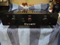
I finally (finally!) finished putting together my first self-designed headphone amp. I think it came out pretty well.

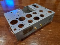
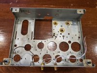
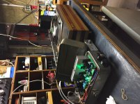
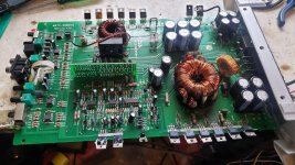
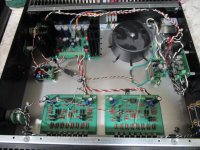
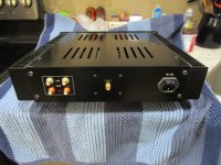
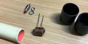
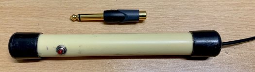
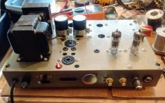
This amp is a pure junkbox project. The goal was to make a useful toy out of parts I've collected over the years. The idea was to NOT buy ANY parts, if at all possible. The amp's built in a discarded Heathkit W5M chassis a friend gave me something like 15 years ago. I also wanted to put to work things I've learned from folks here on diyAudio. Thanks to everyone who gave me advice and instruction along the way. (I know the "strain relief" on the AC cord is laughable. I promise I'll do better next time.)

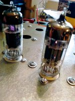
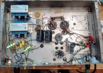
It was pretty funny how many gremlins were tripping me up today. The first time I brought the amp up on the variac it blew its fuse. Turns out there was a faulty rectifier diode. Replaced that and brought the amp up again. This time the fuse held. Now the right channel tube's heater wasn't lighting up. A little jiggling of the pins in the socket and that problem went away. Weird. I checked for a cold solder joint, but all seemed fine. Oh well. Brought it up again. All seemed to be going well so I connected RCA cables to the inputs and gave it the Bzzzzt Test (touch the central pin in each RCA plug in turn, slowly turn up the volume, listen for the bzzzzt from each channel in turn). Hmmm, no sound from the right channel. Oh no... Continuity checked out OK. All resistances OK, including both OPTs. The output jack? Brought it out, disconnected it. Clip-leaded in a new jack and there it was. Would you believe a defective jack? Man, I'm snake-bit!

Finally, all was looking good. I took the amp off the variac, powered it directly from house AC. All good. Time to listen.

I connected the amp to my PC's soundcard, plugged in a pair of beater headphones, gave it a listen.

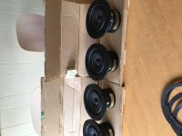
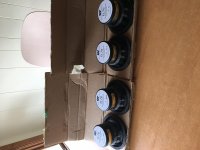
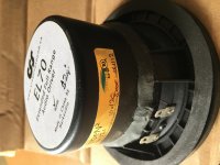
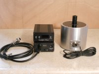
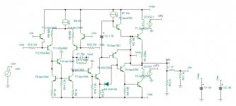
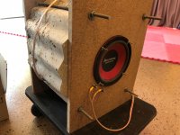
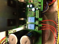
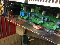
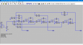
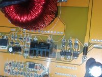
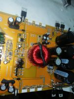
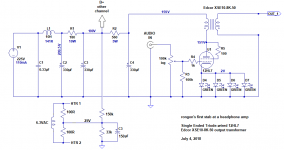
Four hours later and I'm still listening. This thing sounds really, really good to me. Clean and clear. Not "warm." Lots of impact. Drums go "thwack." Isaac Stern's violin is really nice. Not 'electronic' sounding at all. Bass has real body. I think it goes low enough to be enjoyable. (I was worried about that.) Overall the amp is 'livelier' sounding than my Objective 2 amp. I don't want to go down the rabbit hole of audiophool jargon blather, so I'll just post some pictures of my fuggly build and the schematic of the basic circuit.

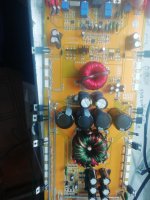
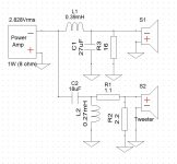
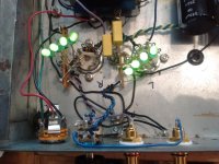
In the schematic there's a B+ supply common to both channels, then the DC splits off into an RC filter for each channel of 560R and 330uF (R2 and C4). Later I hope to replace that RC filter with a simple voltage regulator member Elvee basically designed for me (thanks Elvee!). The idea is to have a couple of pretty 0D3 glow tubes standing on top of the chassis. I rigged it up with the passive supply to get it going.

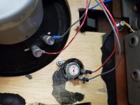
I was worried about hum from AC heaters. I very carefully followed the suggestions in the "Heater Wiring - The Good the Bad and the Ugly" thread. I'm getting absolutely zero hum of any kind. (I'm so happy about that.) I also followed the suggestions for grounding layout in Merlin Blencouwe's Valve Wizard Grounding article. That worked perfectly too. (I'm elated about that.) I also referred to Merlin's "Designing High Fidelity Tube Preamps" book a lot, which was especially helpful for power supply stuff.

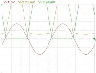
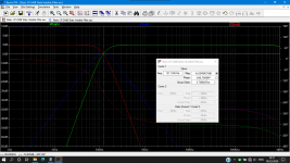
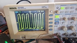
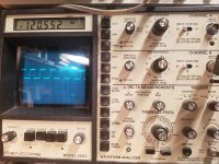
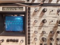
So it's a success. Gain is about 2X, I think. I haven't measured it yet, as I don't have my signal generator and scope fully accessible right now. I need to get to that.

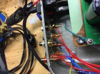
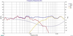
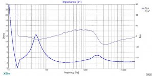
Finally, I need to figure out whether I need damping resistors across the OPT secondaries for using the amp with 300 ohm headphones. The amp sounds excellent to me into my Fostex T50RP headphones (60 ohm impedance). It also sounds clean and clear into my Sennheiser HD650 headphones (300 ohms), but these supposedly 'dark-sounding' cans sound bright and a little bass-shy from this amp. I'm wondering if that's an artifact of putting a higher than optimal 300 ohm load on the nominal 50 ohm secondary. This weekend I'll have some time to clip in some different values of parallel resistors to see what sounds good to me.

But for now, I'm just happy this thing is working well. Thanks again to the diyAudio community.
--

Attachments

  • rongon_12HL7-triode_SET-headphone-amp_4July2018.png
    rongon_12HL7-triode_SET-headphone-amp_4July2018.png
    26 KB · Views: 1,003
  • IMG_20180704_180829235.jpg
    IMG_20180704_180829235.jpg
    500.6 KB · Views: 991
  • IMG_20180704_180741879.jpg
    IMG_20180704_180741879.jpg
    574.2 KB · Views: 873
  • IMG_20180704_180240405.jpg
    IMG_20180704_180240405.jpg
    679.9 KB · Views: 856
  • IMG_20180704_180249480.jpg
    IMG_20180704_180249480.jpg
    765.1 KB · Views: 940

Desktop Open Baffle Speaker System Project

After building and using a pair of on-wall mini bookshelf speakers, I decided to tear them down and build something with better bass and accuracy.

Building a set of mini on-wall speakers in wood was on the cards, but with one bad experience with a bookshelf speaker that turned out too shallow, I decided it was not worth the risk and effort at this point, maybe later. I also was set on using existing speakers instead of buying new ones - Fostex and so on, lets see what I can do.

Initial experiments consisted of using the existing Realistic 1011 or so woofers, and the unknown NS speakers that I purchased at the local electronics store for less than $6 a pair. Of course there will be the opportunity to spend later if I see the need to.

Initial testing with the TEA2025 PC speaker amplifier and a software equalizer revealed that the Realistic could output suffcient bass, but output volumes were very low. On the other hand the NS speakers sounded good enough, with a coil hacked from a crossover I bought many years ago, seemed adequate for the purpose: my only alternative now for desktop or in-room music is the mono Bluetooth speakers that I am now somewhat tired of.

A cardboard prototype showed some interesting results - the speakers were best about 60 cm from the wall, and lifting the speakers 30 cm above the desk improved the sound and made the distorted ringing sounds from the desktop disappear. So reflections are a factor after all!

Now all that remains is to build the baffles and fit the speakers, and find a sufficient coil for the crossovers.

Where to find isolating shoulder washers for panel adapters

Hi Folks,

I need a source for isolating shoulder/flang washers, the same as the ones attached to these RCA connectors

Yellow RCA/Phono Female F to F Panel Mount Adapter for Wall Plate Chassis Mount

To fit

--9.5mm connector diameter
--10.5mm rack hole diameter

Essentially, I am using a metal 1U rack mount to create a patch panel for Amp and Speaker testing and have a job lot of RCA and Speaker Binding through adapters. The Speakers ones didn't come with isolating washers and are the same size as the standard RCA ones.

Appreciate any links. Thank you

Class d recomendation for esl speaker

I’m about to make an upgrade from my Sure AA-AB32313 + Meanwell HLG-320-36A.
The speakers are Final sound 1000i, they do not dip to crazy low Ohms in the bass like most ESL speakers. A benign 4 Ohm load is/was promissed by Final sound.

The options I’m looking at are:

Hypes nCore board/diy
Ice edge board/diy

Crown DCi analog

Should I add other amps to the list?

The reason for upgrade is that I find the Sure AA-AB32313 + Meanwell HLG-320-36A combo is lacking in ”bass tightness”

Edit: Crown CTs has redicoulusly high damping factor From lowest hz to high hz. I’ll add it to my list allso.

Kr-950

Hi,I recently owned a Kenwood KR-950B Receivier, it`s actually not bad,it sounds very well with my speakers.(some older Noname speakers) The question I have is: there is an In- and Output(l&r) at the back writed on with "ADP". Has anyone an Idea for what it is? maybe a split after the preamp?

greetings
BastiB

Inexpensive Bluetooth amp for Radio conversion

Hello

I am of very limited ability in this area but always willing to have a go!

Looking for some advice on converting an old valve radio to a Bluetooth speaker

Plan is to leave all the old stuff there to keep the opportunity for a proper refurbishment later by someone more able

I have already bought a Sanwu tda 7492p Bluetooth amp , which works well enough for my needs except that the aux input, which seems to connect then disconnect,or the BT needs to be connected and paired but silent. Any thoughts?
I plan to use a laptop power supply,keeping all the HT all safely locked away

Next question is, if the BT is coming in stereo and I have only one speaker....how do I solve it and get both channels

Volume control, to make a gesture to authenticity it would be nice to use a pot for volume control (and power switching)

Dial lamps, it currently uses e10 filament bulbs, would warm white leds be an reasonable alternative

This is an experimental low budget project, based more on curiosity than need!

Any advice on this or a more suitable amp would be appreciated

Many 5hanks

SSR Hum

Ai do not remember having this issue before. But, seems I am on a roll.

Bought a nifty 40A SSR off the WEB. Hooked it up so USB controls the rest of the stereo. Serious hum in the transformers. Load dependent. Now before, I just had a very light load on a 10A SSR, but did not notice any hum.

So, swapped in the 10A. Still hum, but only when load over an amp.

Drug out the scope. I can just barely tell a switching glitch for the triac, but nothing I woudl think upset the transformers. Anyway, guess I am looking for a relay. I wanted the SSR as it pulls so little from the USB. Best relay I found is 70mA.

Anyone else have this?

Who Likes Gradient?

I left CES pondering a couple of things:

1) Dipoles sound really nice, particularly Vanderstien
2) Coaxes solve a lot of problems - the Kef LS50 was probably the best 'bang for the buck' that I heard at the whole show
3) tweeters in horns can't hold a candle to tweeters in waveguides

An obscure speaker from a manufacturer in Finland combined some of the best attributes of all these solutions, and I was surprised by how good it sounded. Particularly since it's a brand that seems often ignored.

I'm a bit curious if anyone else has evaluated them, particularly if they've heard John K, Linkwitz, or Vanderstien dipoles.

Besides sounding good, I was a bit surprised by how good the directivity is. With such a strangely arrayed set of drivers, I would expect to see ugly gaps and discontinuities in the polar response, but it's quite good!

GradientHelsinki_birch_sm2.jpg

810Helfig3.jpg

baa3d0adc88f6e6973cddb27c5b74fe0.jpg

1212KEF50fig4.jpg

Here's a couple of John Atkinson's measurements. The first is from the Gradient Helsinki, the second is from the Kef LS50 (which is also very good IMHO.)

May Kenwood KFC-HQ718 car speakers used in home hifi?

Reading some threads dealing with car speakers in home wifi, it seems that all in all this is not the best idea. However, I have a pair of Kenwood KFC-HQ718 speakers lying around and I want to check the possibility to use them for home hifi. Do you think it would be possible to get good results? any prefered design? or it will be a total waste of time?
Assuming my amp is able to drive 4 Ohms.

Thanks,
Aviv.

Currently available TO-264 insulators?

I am planning an amp build using a pair of TO-264 devices on the output of each channel, but am having trouble finding a matching thermal pad which is not electrically conductive. Datasheets for Bergquist suggest there should be Sil-Pads of appropriate size, but I cannot seem to find them in-stock at my usual suppliers (Arrow, Mouser). It looks like the DIY Audio Store's Keratherm pads will work, but the price is rather steep.

Does anyone know of thermal pads of sufficient size and affordable price? Is it possible to make these work with careful orientation?

Anyone know how to do a proper diode mod on a Sansui 5000 F1040 Board?

Just got a Sansui 5000. Heatsink very hot. Found out the bias in this thing was running at 450ma! Ouch. Lucky It dont have blown outputs. Was able to turn pot all the way own and get 26ma but something is obviously wrong with this driver board. Heard there is diodes that go bad and there is a mod but cant seem to find how to actually do the mod. Anyone familiar with this mod?
Projects by fanatics, for fanatics
Get answers and advice for everyone wanting to learn the art of audio.
Join the Community
507,772
Members
7,887,779
Messages

Filter

Forum Statistics

Threads
406,200
Messages
7,887,779
Members
507,772
Latest member
Hypertone