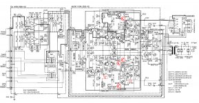
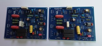
Purifi 1ET400A / Hypex NC500 Input buffer with Korg Nutube valve [Updated]
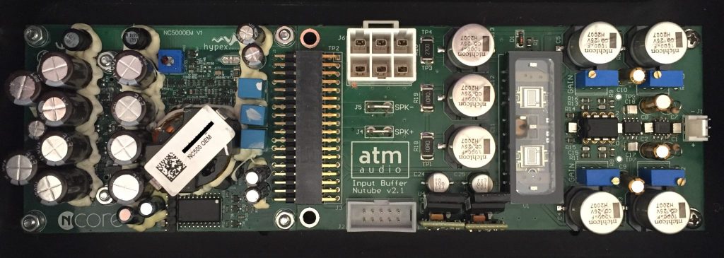
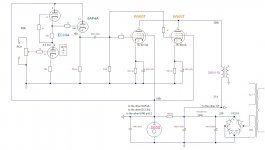
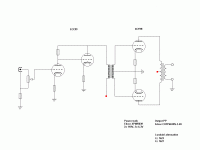
This buffer is based on the double Nutube triode from the Japanese manufacturer Korg. The circuit is valid for Class D power modules, model 1ET400 from manufacturer Purifi Audio and model NC500 from manufacturer Hypex (with some limitation). They both use the same expansion connector and are fully compatible.
First of all, we must bear in mind that, with this buffer, we want to achieve the maximum power, dynamics, damping factor and efficiency, typical of class D modules, and mix it with the warmth that valves provide. This is not a buffer with very low distortion, for this we already have other buffers in our store with very good results. This is a buffer that gives us a sound very similar to vacuum valves.
This buffer works fully in differential mode, so the input has to be balanced with an XLR connector (or TRS). With the balanced audio input, we provide an appropriate output signal to attack the balanced input of the power module. In the case of using an unbalanced audio signal (with RCA connection), we will have a loss of gain of 6dB, which is equivalent to four times less output power.
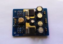
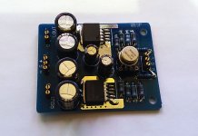
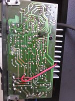
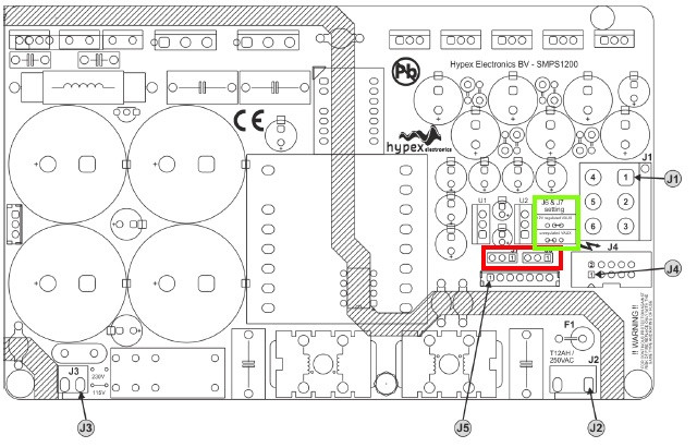
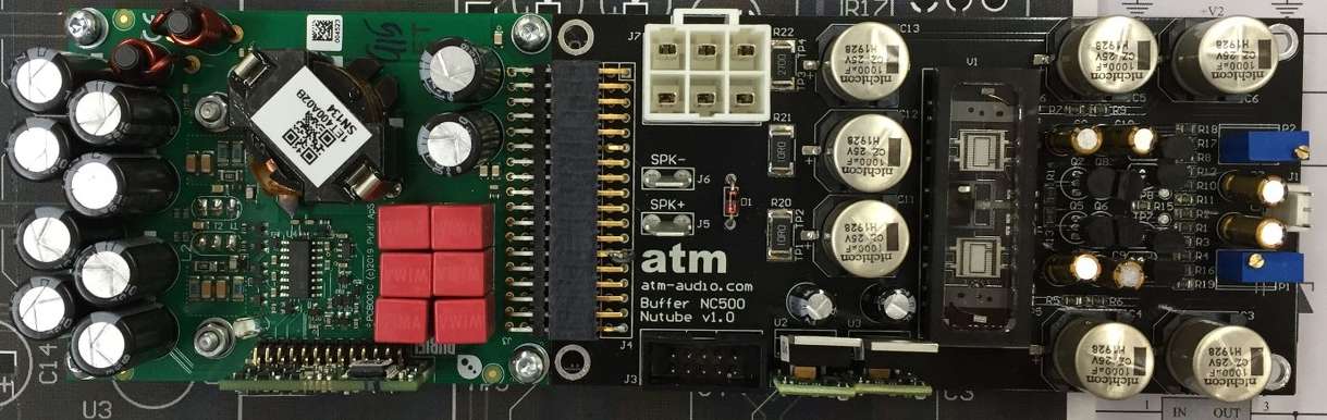
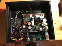
The circuit is prepared for use with the original Hypex power supply, model SMPS1200/A700, in the case of use with the NC500 module, or with the model SMPS1200/A400, in the case of use with the Purifi Audio module. In both cases, an important point must be taken into account: Jumpers J6 and J7 (Vaux marked in red) must be placed in position 2-3 (unregulated Vaux) as indicated in the green box. This way we will obtain the correct voltage to supply the circuit in J4 connector.
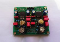
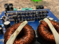
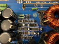
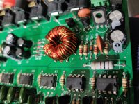
The circuit is made with the best medical grade and audiophile grade electronic components. The resistors are made of metallic film with a 0.1% tolerance. Electrolytic capacitors are Nichicon special for audio. Sparkoslabs very low noise voltage regulators have been used. The two variable resistors at the top of the pcb adjust the maximum distortion value and the two variable resistors located at the bottom adjust the output signal in differential mode. These resistors are factory adjusted to the optimum value so that the power module works in the best conditions. It is not advisable to touch these resistors to avoid a malfunction of the circuit. Only if laboratory instruments are available could they be minimally varied until the desired function is achieved.
The circuit is adjusted so that with, an input sensitivity of 500mV (balanced), an output power of 160W RMS at 4 ohms and 2,67% THD+N (with Purifi Audio).
Higher output powers can be achieved by increasing the input signal, but the distortion will rise exponentially.
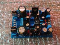
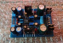
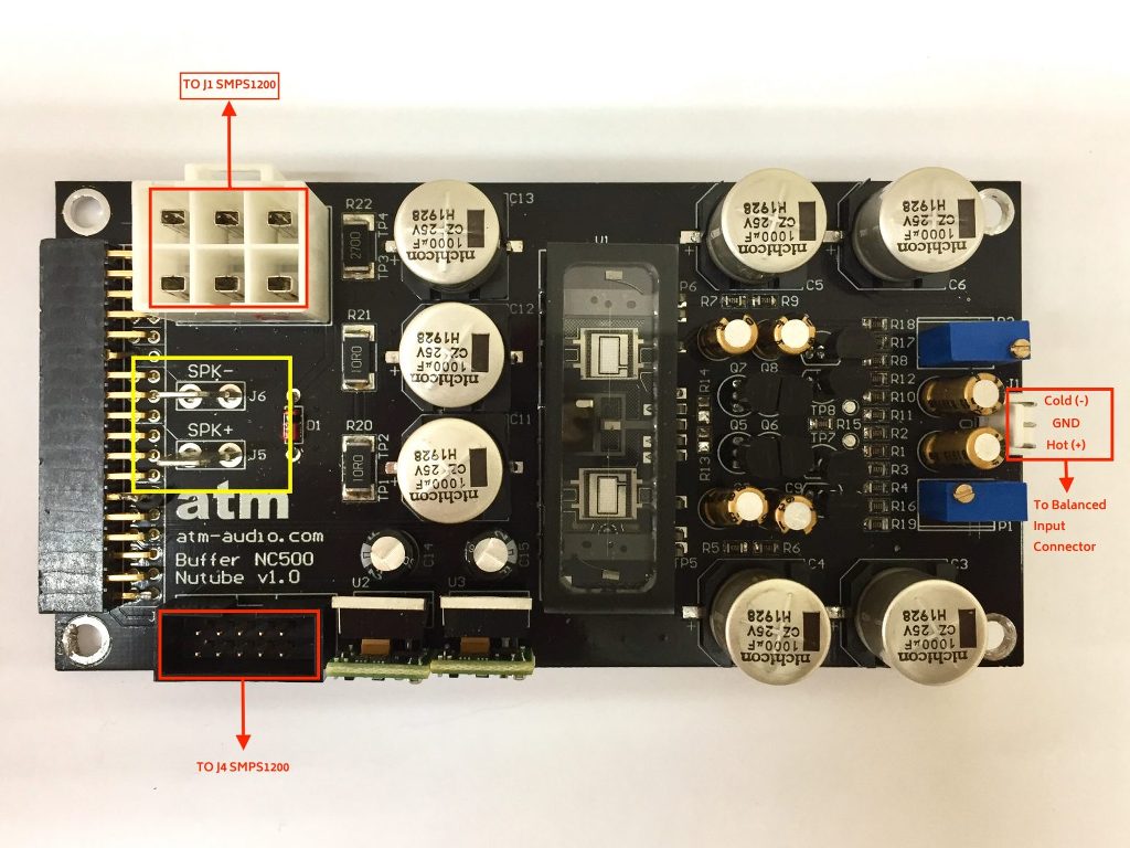
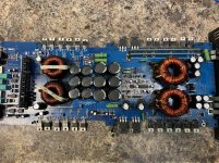
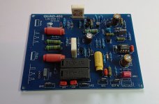
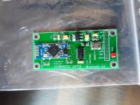
The PCB measures 125 x 63mm and has several connectors.
- J1 Balanced audio input connector.
- J3 IDC connector 2x5 flat cable.
- J4 Angled connector 2x18.
- J5 Speaker Fastom connector (+)
- J6 Speaker Fastom connector (-)
- J7 Power connector.
Connections are made as follows:
- J1 Buffer Nutube to balanced input connector (XLR o TRS).
- J3 Buffer Nutube to J4 SMPS1200/Ax00 with flat cable and IDC connectors.
- J4 Buffer Nutube to power module.
- J5 Buffer Nutube to Speaker (+)
- J6 Buffer Nutube to Speaker (-)
- J7 Buffer Nutube to J1 SMPS1200/Ax00.
The SMPS1200/Ax00 J4 connector has the following wiring:
- J4.1 + 21Vdc
- J4.2 - 21Vdc
- J4.3 GND
- J4.4 No Con.
- J4.5 No Con.
- J4.6 Amp. enable
- J4.7 No Con.
- J4.8 No Con.
- J4.9 GND
- J4.10 DC Error
The SMPS1200/Ax00 J1 connector has the following wiring:
- J1.1 VDR+
- J1.2 HV+
- J1.3 GND
- J1.4 VDR-
- J1.5 HV-
- J1.6 GND
The kit consists of the following material:
- Buffer Nutube PCB (2 units)
- Molex Connector J1 with pins (2 units) w/o cables
- Speakers female Fastom Connector (4 units) w/o cables
The rest of the connectors and cables are usually included in the power modules. They can be obtained individually on the Hypex or Purifi website
Details in
Buffer Korg Nutube for Hypex NC500 and Purifi Audio 1ET400 | atm-audio.com
Buffer with op. amp.
https://atm-audio.com/product/buffer-hypex-nc500/
[UPDATED Summer 2020]
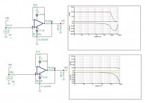
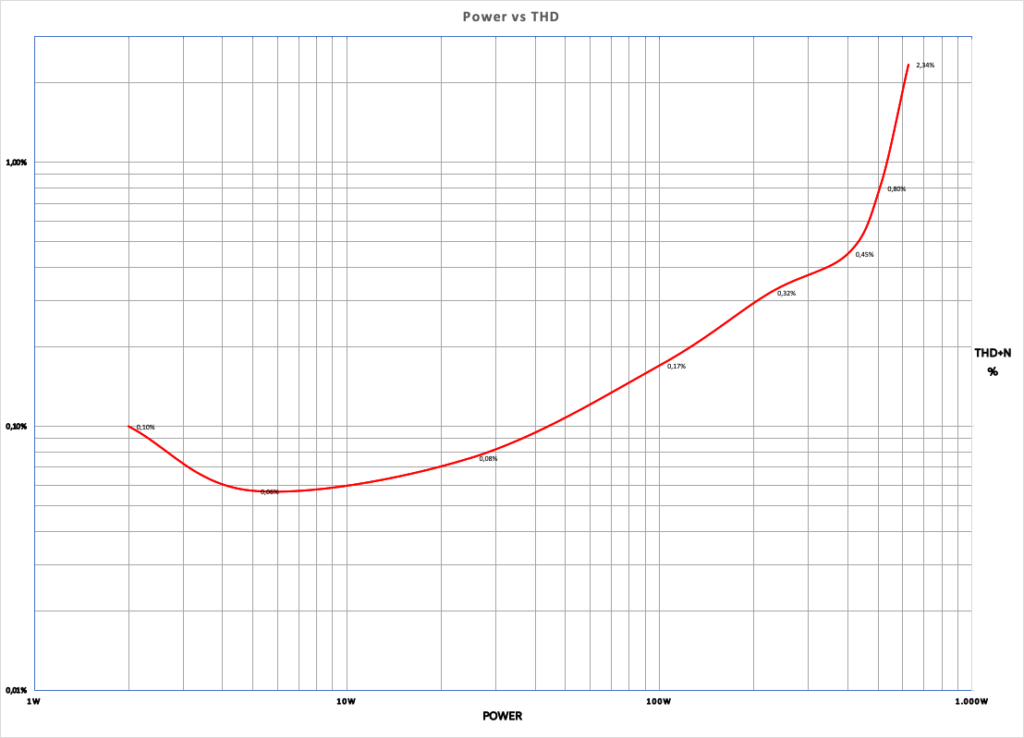
We have recently made a new version of the Nutube buffer (V2). We have replaced JFET transistors and used very low noise instrumentation op amps as impedance adapters. In this way, we have managed to reduce the total harmonic distortion (THD) throughout the power range, especially in the 100-500W range, which is where the V1 buffer rises a lot, keeping it below 1%.
This curve was measured with the Nutube V2 buffer connected to the Hypex NC500 module.
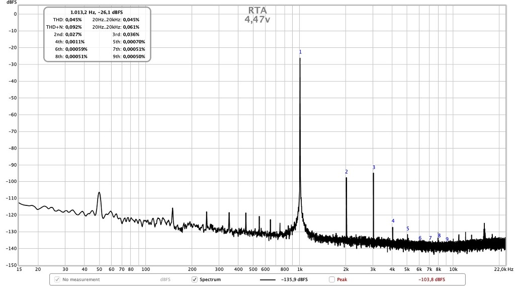
We have achieved, for a +/-1 VRMS differential input signal, an output voltage of 141 VPP before clipping. The total harmonic distortion + noise (THD+N) is 2.34%. The distortion of the second harmonic (2H) is 0.27%. With this numbers, we have the equivalent of a 625 WRMS tube amplifier @ 4 Ω, with a total gain of almost 36,19 dB.
In the next graphs you can see some measurements of the THD+N at 1 kHz and its harmonics depending of the output voltage:
 https://atm-audio.com/500-w-hybrid-power-amplifier-with-nutube-valve-for-hypex-nc500/
[UPDATED November 2020]
https://atm-audio.com/500-w-hybrid-power-amplifier-with-nutube-valve-for-hypex-nc500/
[UPDATED November 2020]
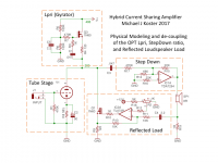
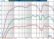
These are the buffer measurements with the Purifi Audio module.
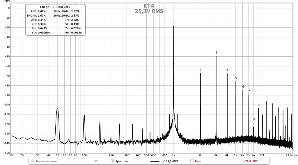
For a differential input signal of +/- 500mV RMS, we have an output voltage of 98 VPP before clipping. The total harmonic distortion + noise (THD + N) at this point is 1.53%. The distortion of the second harmonic (2H) is 0.037%. With these numbers, we have the equivalent of a 300 WRMS tube amplifier at 4 Ω, with a total gain of 34 dB.
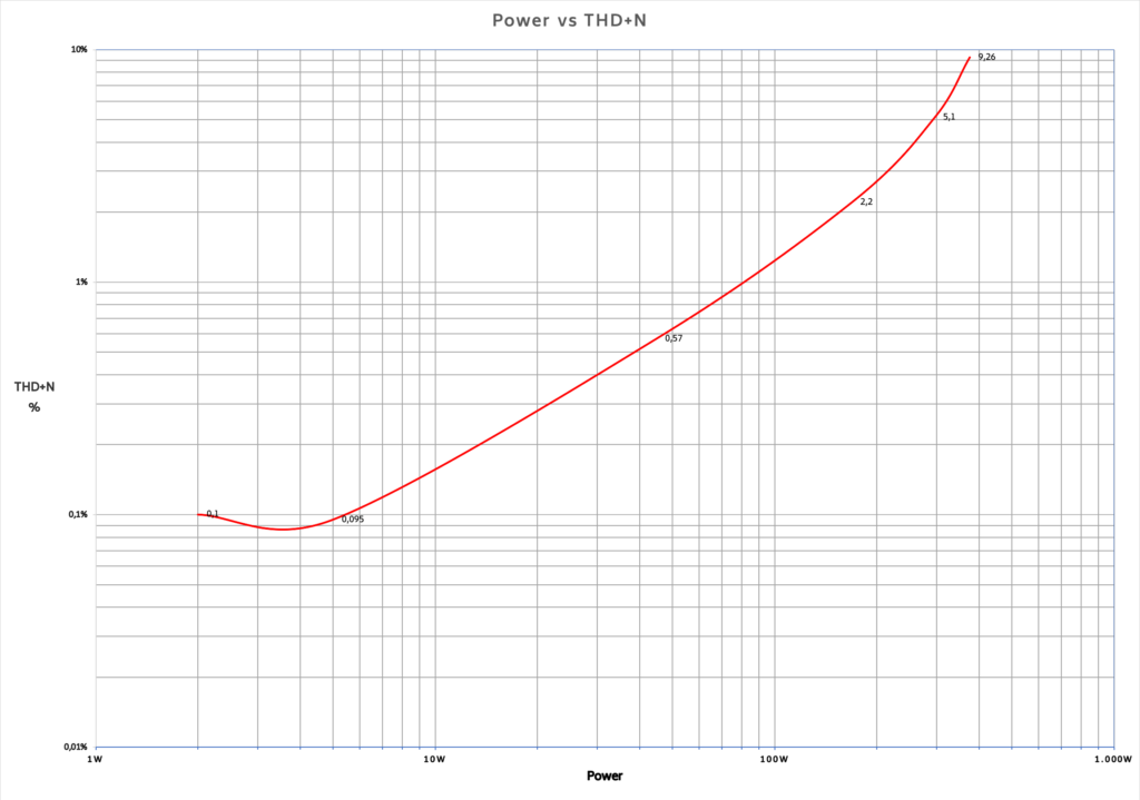
As can be seen from the graph, for 100 WRMS amplification the distortion is only 0.35%. Up to 50W the distortion is less than 0.2%
Power vs THD+noise
In the next graphs you can see some measurements of the THD+N at 1 kHz and its harmonics depending of the output voltage:
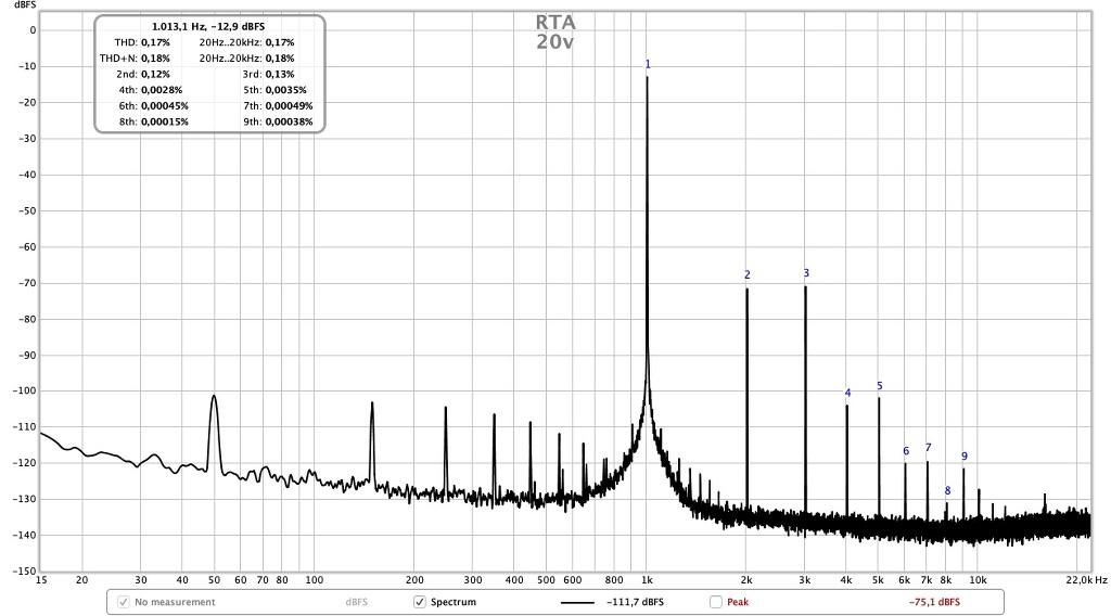
(5W @ 4 Ohms)
(100W @ 4 Ohms)
https://atm-audio.com/300-w-hybrid-power-amplifier-with-nutube-valve-v2/


 , ask stupid questions and experiment. I'll just call it 'applied electronics' so I can feel better.