Long time member, infrequent poster here 🙂 After years of planning on "getting around to" building a proper set of towers I finally have the space, tools, and time to start on this project, as well as a livingroom in what is hopefully our "forever home" to put them in.
Some background my my speaker building experience and this project:
Goals for the project
Baseline Driver list:
Peerless HDS Exclusive 8 (830884) - Firm
Peerless HDS Exclusive 5 1/4" (831882) - Firm
Dayton DC28F-8 1-1/8" Tweeter
Oddly enough I searched through my post history and found This Thread that I started in January 2007 when I was starting to think about building a proper set of towers, so this project kick-off has been a long time in the making 🙂 I also just realized that my "Black 300zx" has long since been sold and now a white 300zx resides in the garage 😛
Some background my my speaker building experience and this project:
- Like many, my interest in audio started with my car. Initially focused around off-the-shelf 2-way passively crossed system and evolving into actively driven systems including a setup involving Peerless "Exclusive" HDS 8" midwoofers with Image Dynamics Horns
- My first venture into home speaker building was a set of the Dayton Audio 8" MTMs Here is an example
- A set of bookshelfs based around the CSS WR125 driver with a cheap Dayton tweeter (cross-over design copied from a published project)
- After removing the Peerless Exclusive 8s from my car and mothballing them(10-12 years ago) I grabbed a matching set of Peerless Exclusive 5 1/4's before they were discontinued, with big plans on using them in a TMW tower build
- Also leftover from another automotive install are a pair of Dayton DC28F-8 1-1/8" silk dome tweeters which I'd like to utilize in this build, provided that they pair well with the Peerless mid & woofer drivers
Goals for the project
- Finally get some experience designing crossovers. I realize jumping into a 3-way setup may be a steep learning curve, but if I don't try to tackle this now I'll probably never get to it
- Make good use of the Peerless drivers which were pretty well regarded when I purchased them. Utilizing the Dayton tweeters is a nice-to-have, but I wouldn't loose sleep over tossing them if needed
- As these are going to be prominently displayed in our living room, I will be considering them a piece of furniture when it comes to cosmetics. Bodies will be primarily MDF, but I do plan to incorporate some hardwood accents and matching veneer
Baseline Driver list:
Peerless HDS Exclusive 8 (830884) - Firm
Peerless HDS Exclusive 5 1/4" (831882) - Firm
Dayton DC28F-8 1-1/8" Tweeter
Oddly enough I searched through my post history and found This Thread that I started in January 2007 when I was starting to think about building a proper set of towers, so this project kick-off has been a long time in the making 🙂 I also just realized that my "Black 300zx" has long since been sold and now a white 300zx resides in the garage 😛
Last edited:
Step 1 - I worked out an initial cabinet design. WinISD showed a 1.75-2.0 ft^3 enclosure tuned to ~30Hz or so looked pretty good for the 8s and I found a thread on here involving them that also was right around the 1.75 ft^3 range with similar tuning.
After playing around with the design a bit I decided that I wanted a front facing port to allow me to incorporate a hardwood trim ring for the port. I also decided that I wanted to have curved sides with matching hardwood veneer. All non-wood surfaces will be gloss black.
The room that they'll go into:

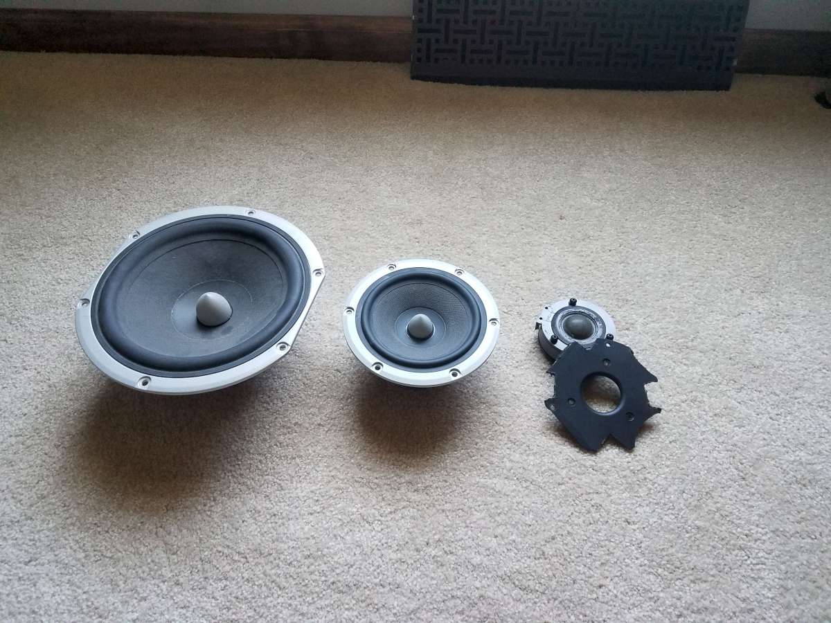
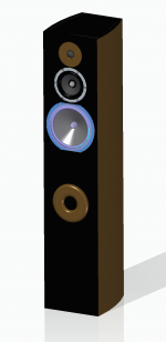
The drivers that I plan to use. Note - the automotive install that the Dayton Tweeters were used in required me to hack up the mounting flange for clearance. If I used these I plan to fab new faceplates out of matching hardwood.
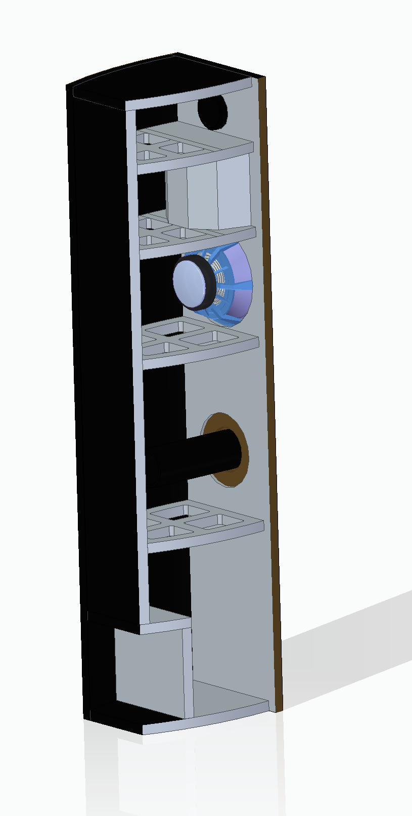
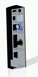
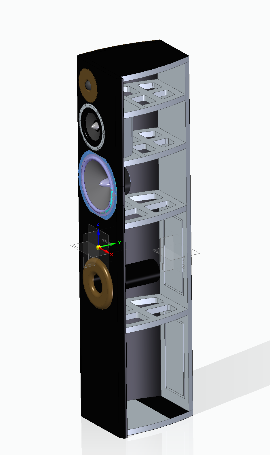
And a few CAD renderings of the initial cabinet design. 47.5" tall, 10" wide front baffle, approx. 11" deep. Brown surfaces will be solid wood (port ring, tweeter faceplate) or veneer (left and right sides). The height and depth were constrained to these values to allow me to use one roll of 24" x 96" veneer to finish them. Each brace has a different spacing (relative to the others) which should help to avoid having multiple faces resonating at the same frequency. The cavity in the bottom rear is for the crossover circuitry and will allow me to easily tweak the crossover design as needed.
(not sure why the images are distorted in the preview, they look fine if you click on them)

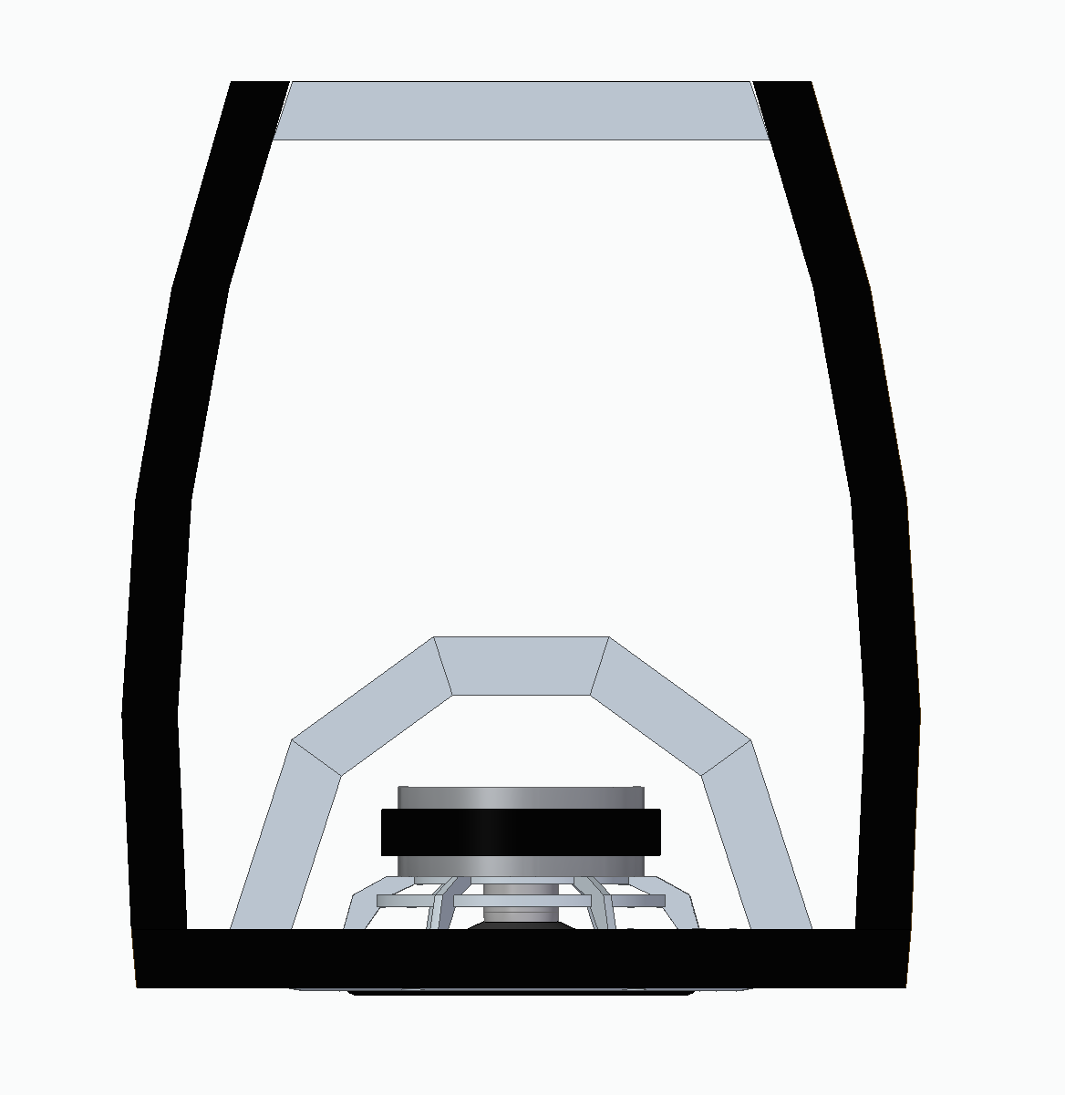
One thing I've learned from my readings on here (and elsewhere) is that non-parallel walls are good when making an enclosure for mids. I ended up settling on the enclosure geometry below for the midrange. Each of the five mitered walls is the same width and angle which should help fabrication. I'll be adjusting the internal volume as needed as I get deeper into the design process.
After playing around with the design a bit I decided that I wanted a front facing port to allow me to incorporate a hardwood trim ring for the port. I also decided that I wanted to have curved sides with matching hardwood veneer. All non-wood surfaces will be gloss black.
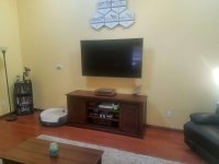
The room that they'll go into:
The drivers that I plan to use. Note - the automotive install that the Dayton Tweeters were used in required me to hack up the mounting flange for clearance. If I used these I plan to fab new faceplates out of matching hardwood.
And a few CAD renderings of the initial cabinet design. 47.5" tall, 10" wide front baffle, approx. 11" deep. Brown surfaces will be solid wood (port ring, tweeter faceplate) or veneer (left and right sides). The height and depth were constrained to these values to allow me to use one roll of 24" x 96" veneer to finish them. Each brace has a different spacing (relative to the others) which should help to avoid having multiple faces resonating at the same frequency. The cavity in the bottom rear is for the crossover circuitry and will allow me to easily tweak the crossover design as needed.
(not sure why the images are distorted in the preview, they look fine if you click on them)
One thing I've learned from my readings on here (and elsewhere) is that non-parallel walls are good when making an enclosure for mids. I ended up settling on the enclosure geometry below for the midrange. Each of the five mitered walls is the same width and angle which should help fabrication. I'll be adjusting the internal volume as needed as I get deeper into the design process.
Attachments


Last edited:
If you could fab/use a waveguide for the tweeters that would be even better!
Hmmm, very intriguing idea, although I have zero experience/knowledge on waveguide design and I think I'm already taking on a significant challenge w/ a 3-way cross-over design. I don't want this to turn into a never-ending project which never actually gets built because I'm constantly adding to the scope.
Can you recommend any resources to read to get my feet wet? If I can get an idea of the required footprint on the face of the cabinets, perhaps I can design them in such a way that I can start with a standard faceplate for the tweeters and replace them with a waveguide in the future 😎
I forgot to add my fourth goal for the project: To finally figure out Speaker Workshop 🙂 I started to dabble with it back in the 2006/2007 timeframe, including building the Wallin 2 jig, but never was able to really make any headway using it. Between setup/calibration issues and not having the time/knowledge to adequately follow the documentation, I stalled out pretty quickly.
I'm fully expecting to hear that SW is woefully outdated, and that better/easier packages exit. That's fine, maybe I'll convert after I get the satisfaction of tacking it 🙂
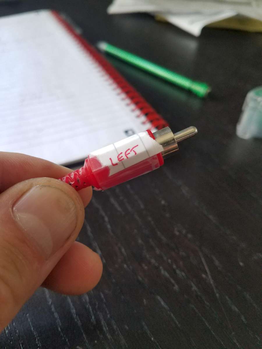
I started by dusting off the Wallin Jig and my old cables, and doing a DMM check on everything to make sure that age hadn't compromised the equipment. Wallin Jig checked out OK, but I was surprised to find that the 3.5mm stereo ->RCA cables I had used red covers on the LEFT channel RCA plug😱 Maybe assuming Red=Right was half of my issues in the past
Labelled so I don't forget:
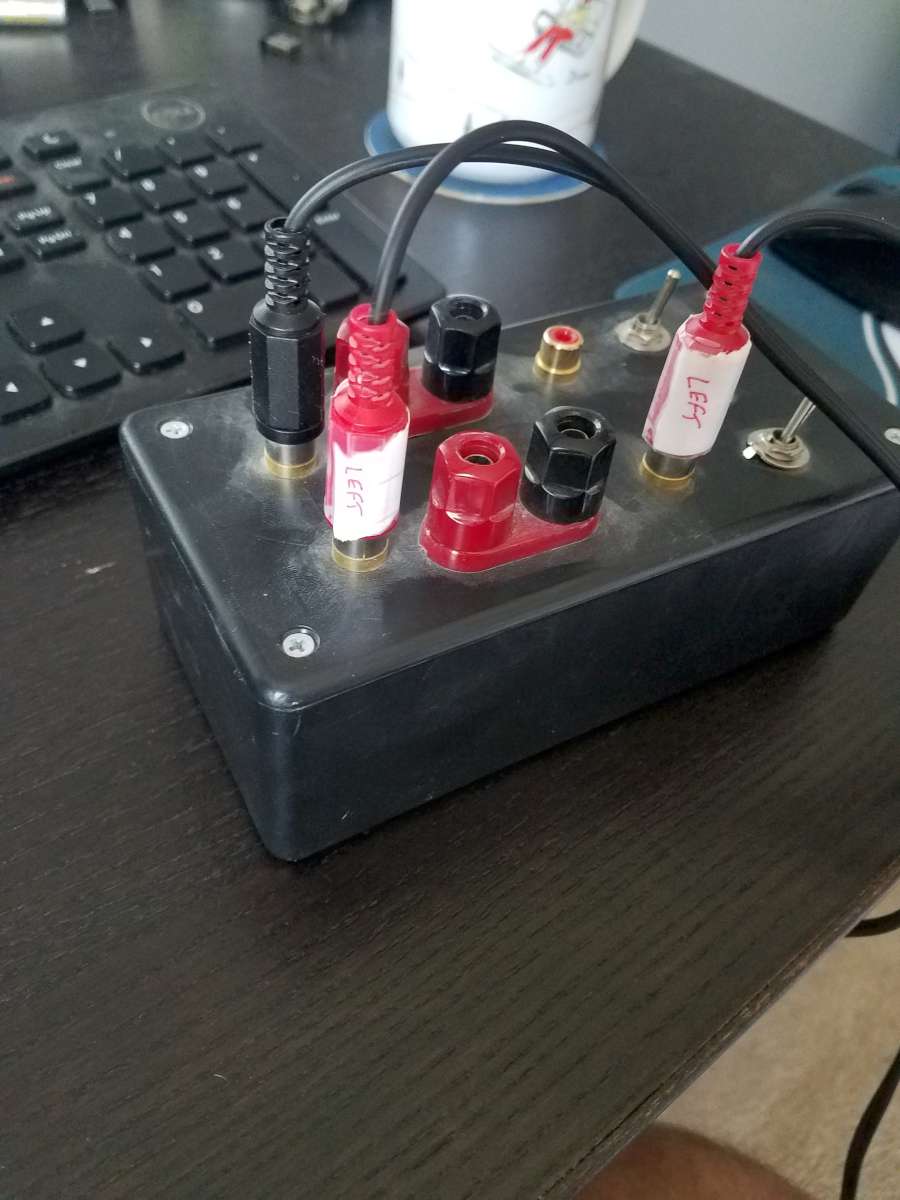
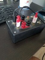
Setup for calibration:
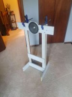
After getting what seemed to be a good calibration on the souncard & jig, I whipped up some stands to mount the drivers for free-air impedance measurements:

Comparing them against the datasheet impedance curves looked pretty darn good. Calculating the T/S parameters from the data also resulted in values that were within 5% of the datasheet! Satisfying progress 🙂
With those steps tackled I moved onto tracing the datasheet F/R curves into .FRD files using FPGraphtracer to allow me to dabble in some preliminary x-over design. Although I'll be taking in-enclosure F/R measurements before I design the x-overs, I wanted to get a sense for what order networks might work well so that I could make sure I had enough space allocated in the enclosure for the networks.
I pretty quickly realized that I hadn't allocated nearly enough space in the "crossover cubby" that I designed. Glad I realized this before I cut wood. A little bit of CAD work and I ended up with this revised design which included two removable access panels to mount cross-over components on. I used the footprint dimensions of this off-the-shelf 375hz/3000hz 2nd order network from Parts Express and a guide for how large to make the access panels. I could fit one of these crossovers on each access panel so I should have plenty of room to go 4th order if I need to.
95% Final enclosure design (note - I pushed the mid/tweeter off to the edges based on some Baffle Diffraction Simulations...not sure if I'll keep them there or not yet).
A quick flat layout shows that I'll be able to fit all of the 3/4" parts on a single 4x8 sheet! The duplicate baffles represent the double-thickness front baffle that I haven't actually detailed out yet.
Next step is to finalize some of the joints, finalize some decisions on speaker placement and baffle edge dressing (roundovers vs chamfers), then start building some cabinets 🙂
I'm fully expecting to hear that SW is woefully outdated, and that better/easier packages exit. That's fine, maybe I'll convert after I get the satisfaction of tacking it 🙂
I started by dusting off the Wallin Jig and my old cables, and doing a DMM check on everything to make sure that age hadn't compromised the equipment. Wallin Jig checked out OK, but I was surprised to find that the 3.5mm stereo ->RCA cables I had used red covers on the LEFT channel RCA plug😱 Maybe assuming Red=Right was half of my issues in the past
Labelled so I don't forget:
Setup for calibration:
After getting what seemed to be a good calibration on the souncard & jig, I whipped up some stands to mount the drivers for free-air impedance measurements:
Comparing them against the datasheet impedance curves looked pretty darn good. Calculating the T/S parameters from the data also resulted in values that were within 5% of the datasheet! Satisfying progress 🙂
With those steps tackled I moved onto tracing the datasheet F/R curves into .FRD files using FPGraphtracer to allow me to dabble in some preliminary x-over design. Although I'll be taking in-enclosure F/R measurements before I design the x-overs, I wanted to get a sense for what order networks might work well so that I could make sure I had enough space allocated in the enclosure for the networks.
I pretty quickly realized that I hadn't allocated nearly enough space in the "crossover cubby" that I designed. Glad I realized this before I cut wood. A little bit of CAD work and I ended up with this revised design which included two removable access panels to mount cross-over components on. I used the footprint dimensions of this off-the-shelf 375hz/3000hz 2nd order network from Parts Express and a guide for how large to make the access panels. I could fit one of these crossovers on each access panel so I should have plenty of room to go 4th order if I need to.
95% Final enclosure design (note - I pushed the mid/tweeter off to the edges based on some Baffle Diffraction Simulations...not sure if I'll keep them there or not yet).
A quick flat layout shows that I'll be able to fit all of the 3/4" parts on a single 4x8 sheet! The duplicate baffles represent the double-thickness front baffle that I haven't actually detailed out yet.
Next step is to finalize some of the joints, finalize some decisions on speaker placement and baffle edge dressing (roundovers vs chamfers), then start building some cabinets 🙂
Attachments


Hmmm, very intriguing idea, although I have zero experience/knowledge on waveguide design and I think I'm already taking on a significant challenge w/ a 3-way cross-over design. I don't want this to turn into a never-ending project which never actually gets built because I'm constantly adding to the scope.
Can you recommend any resources to read to get my feet wet? If I can get an idea of the required footprint on the face of the cabinets, perhaps I can design them in such a way that I can start with a standard faceplate for the tweeters and replace them with a waveguide in the future 😎
You can actually buy a variety of waveguides already. The WG 148 R from visaton would probably be the most appropriate one for your design.
Or you could get one of augerpro's waveguides. You'd probably have to ask which one he'd recommend for your tweeter
You can actually buy a variety of waveguides already. The WG 148 R from visaton would probably be the most appropriate one for your design.
Or you could get one of augerpro's waveguides. You'd probably have to ask which one he'd recommend for your tweeter
Any place I can find a quick summary for waveguide dummies on what the performance benefits are?
Waveguides act to channel the sound waves that a driver produces and in doing so alters its off axis performance.
The first benefit this provides is in shaping the off axis response of the driver so that it matches the off axis of the driver it is going to be crossed over to.
For example if you've got a 5" driver, at low frequencies it radiates sound everywhere but as frequency goes up, at some point, it's off axis response starts to drop and it ends up beaming. Usually it is recommended that you crossover a standard tweeter before the driver starts to beam but most people crossover too high in this regard. You actually have to cross over lower than you'd think if you don't want to compromise on this is any way.
For your 831882 you can see in the datasheet that it starts to beam even before 2kHz. Not badly mind you, but the phenomena has already started.
If you were to cross over at say 3kHz the 60 degree off axis would be down by ~8dB. Now a typical tweeter will be radiating sound everywhere at this point. So you've got loads of sound being radiated out even at 90degrees. Crossing at 3kHz causes an abrupt change in the offaxis response. Whereas the woofer had reduced output off axis the tweeter does not. So while the on axis might be flat, the off axis is far from flat. This creates an uneven reverberant sound field and it affects the speakers tonal balance in a way that's usually perceived as negative. Usually it creates a more forward aggressive sound with typical size mid/bass and tweeters.
Obviously this is less than ideal. You need to cross over very low to completely mitigate the problem. Tweeters don't usually like this and the associated tonal balance issues, with crossing over higher, aren't appealing either. A waveguide helps to get around this issue.
Conveniently a 5" waveguide ends up being very well matched to a 5" mid/bass. Go physics. That is the frequency range that a 5" waveguide starts to control the tweeters directivity coincides with the frequency range where a 5" mid/bass starts to beam. So instead of the tweeter radiating sound everywhere it's off axis ends up being focused into a controlled beam.
As the mid/bass starts to beam the tweeter+waveguide starts radiating in a similar radiation pattern. The two are said to have matched directivity because of this. In other words if you look at the 831882 graphs again, and interpret where a 45 degree off axis line might be, look to see where it will be down by 6dB. By my estimation it will be around 3kHz or so. A decent 5" waveguide will show a similar performance and coincidentally here's a good place to crossover.
Both the mid/bass and the waveguide + tweeter start to beam at roughly the same frequency. As frequency goes up they both carry on getting more directional at the same rate but only up until a point. The mid/bass never stops getting more directional but the tweeter does. At some point the tweeter transitions into a region of constant directivity. The trick is to crossover during the region where the waveguide and mid/bass directivities are matching. Too high and the waveguide will be in constant directivity and you'll get a poor match. You can crossover as low as you want however because down low the waveguide and mid/bass directivities track one another it's just you don't have to. You no longer have to crossover before the mid/bass starts to beam you can actually crossover during the transition.
This eases the job of the tweeter and creates a very smooth off axis profile for the loudspeaker as it crosses over from mid/bass to tweeter.
All that off axis energy that the tweeter has, that's being shaped by the waveguide to match the woofer, also gets put to good use as it increases the efficiency of the tweeter at these same frequencies. This increases its output down near the bottom of it's range and after being flattened by the crossover means it has to work less hard, lowering distortion. This means that if you do need to crossover very low, say to a metal cone mid/bass, the tweeter can now crossover lower than it could before.
Above this range, where the tweeter moves into constant directivity, is also hugely beneficial. The far off axis output of the tweeter is reduced by the waveguide and is controlled into a wide beam. Then as frequency goes up even more the beam wdith stays constant. This is in contrast to a normal tweeter where, just like a mid/bass, it too starts to beam where the off axis will droop beyond a certain frequency. The waveguide does not do this and thus creates a far more even sound field as the on, and off, axis are kept very similar.
The additional (and main) benefit to controlling the sound into this beam of constant directivity is that the far off axis, high frequency, sound is significantly reduced in output. This means far less intense room reflections (early reflections) over a frequency range that's very important to imaging. The more reflections you get the less sharp and precise the images are. The more reflective the room is (hard floor and sparse plush furnishing) the more important this becomes. But note that you don't want to stop the room being somewhat reverberant, like typical spaces are, because it's these later occurring reflections that give loudspeaker listening it's spaciousness and appealing quality, vs say something like headphones. Room treatment, while effective in reducing early reflections, also reduces the reverberant field of the room too, which is detrimental. Not to mention room treatment costs money and takes up space you'd rather wasn't taken up.
So in a nutshell what does a waveguide do?
1) Provides a smooth off axis transition from mid/bass to tweeter.
2) Allows you to crossover the tweeter higher than normal easing it's job.
3) Loads the low range of the tweeter lowing its distortion and allows it to be crossed over lower if necessary.
4) Provides a region of constant directivity which...
a) reduces the impact of the early reflections in the room and improves imaging.
b) reduces the speakers sensitivity to the room it's place in.
c) provides a more even sound field so that the off axis sounds just as good as the on axis. Meaning you can move around or sit off centre (or with a friend) and still have things sound the same.
In your case, where you've got hacked up face plates. You could use the hacked up face plate as a method for helping attach the tweeter to a waveguide if necessary. Or just screw the tweeter directly to the waveguide itself.
Augerpros waveguides are designed for specific tweeters and usually require you to remove the face plate. The Visaton WG148 is meant to be mounted to a tweeter with a face plate but it wouldn't matter if this was round or some other shape. The Monacor WG300 is also the same as the Visaton in mounting configuration but it's probably slightly larger than you'd want.
5th Element - thanks for the thorough yet understandable explanation of the benefits. I did notice that while a 3kish crossover point looked OK on axis, it was going to be problematic off-axis.
With a waveguide, does the "at least 1 octave, preferably 2 above Fs" rule still apply to the tweeter crossover point? Or does the low frequency loading allow you to go closer to 1 oct above Fs without issue?
The reduced energy far off-axis could be especially beneficial for me. The livingroom where these will reside is joined with the kitchen on the right side which will the left speaker approx 3-4ft from the left wall while the right will not have a wall near it. A better controlled tweeter "beam" could help mask this difference in boundary conditions.
I'm still not sure if I want to jump straight into a waveguide (unless i can get one designed for me), but you've convinced me to at least design my baffles to accommodate a 5in waveguide. If my free time gets limited I can start with a flat custom faceplate and swap in a waveguide later.
Thanks for the suggestion and for taking the time to give me a concise summary of the benefits
I posted over in augerpro's thread to see what his thoughts are on a waveguide for my Daytons. In the meantime I made a 3rd variation of my front baffle which accommodates the roughly 6"x4" oval waveguide that he has for several tweeters.
Looks like I have plenty of room to make this recess geometry work with a flat faceplate or a waveguide. I'm looking forward to hearing his thoughts.
Looks pretty 🙂
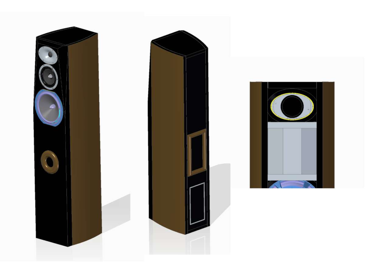
Looks like I have plenty of room to make this recess geometry work with a flat faceplate or a waveguide. I'm looking forward to hearing his thoughts.
Looks pretty 🙂
Attachments

This geometry has been used successfully in horn designs as the rear enclosure, it has advantages. However rather than eliminating parallel surfaces, this makes the distance from the driver to the enclosure walls and back, identical in all directions. You will want to stuff your box appropriately if the midrange is to reach that high in frequency.is that non-parallel walls are good when making an enclosure for mids. I ended up settling on the enclosure geometry below for the midrange. Each of the five mitered walls is the same width and angle which should help fabrication. I'll be adjusting the internal volume as needed as I get deeper into the design process.
Those are some sharp looking cabinets! The elliptical waveguide is a nice compromise in keeping the profile more attractive as well as reducing the C2C distance between the mid and the tweeter. Of course you don't get the same vertical region of constant directivity as you would with a round waveguide but that's usually seen as being less important. The facets around the tweeter are a nice touch in making the cabinet seem narrower. Another benefit of a waveguide though is that it significantly reduces the effect of diffraction from the edges of the cabinet. You wont see the same bumps and wiggles in the tweeters response as you would if the tweeter was just mounted flush to the baffle. Of course the waveguide adds in it's own bump but that's something you want. As a result you could leave off the facets, for easier cabinet construction, and not see too much of a difference vs if they were there. Of course it wouldn't look as nice. 😀
Crossing a tweeter near fs has never really been a problem it's just a rule of thumb for increasing your chances of success. A tweeters distortion profile is the real indicator of how low a tweeter can reasonably go. Some will go down to less than an octave away from fs. Heck some will even go down to fs providing you don't want to listen to them at high volume.
The important thing is that the crossover is actually doing what it should. When a tweeter hits resonance its impedance shoots up. Nominally the tweeter might be 6 ohms and if the crossover is designed to work on that impedance then a massive peak, up to 40 ohms, will significantly alter the way the crossover functions. Instead of the tweeters roll off being a nice smooth, predictable line such as following a typical roll off curve, like a 4th order Linkwitz Riley, you end up with a large discrepancy around resonance and the impedance peak.
The impedance peak usually results in a large peak in output, reducing the crossovers effect and having the tweeter play a lot louder around resonance than it should otherwise be. This not only stresses the tweeter (and sounds bad) but it alters the way the tweeter rolls off and thus alters the way it integrates with the driver below it - this also sounds bad.
So long as the distortion from the tweeter is low and the way the tweeter rolls off is well controlled then you can crossover as close to resonance as you want.
Some cheap tweeters have a very high resonance, say around 2.5kHz, but have very thick ferrofluid in the gap. In the impedance graph of these you'll see hardly any bump around resonance and this does exactly what you'd expect it to, have very little impact on the way the crossover operates at resonance. The ferrofluid helps to dampen the tweeters resonance.
Other tweeters don't use ferrofluid and have very low resonances, some even below 500Hz although around 7-800Hz is more typical. These can have very large impedance peaks. Some require a resonance trap across the terminals of the tweeter to flatten the peak. This doesn't affect the way the tweeter operates it just allows the crossover to work properly around the tweeters resonance.
If you're measuring your speakers impedance/frequency response and simulating the crossover in a suitable CAD program then this isn't usually a problem. Just be aware that there's the possibility for the crossover to do unwanted things where the tweeters resonance is. Often the parallel connected resistor, across the tweeters terminals, in a typical L-pad is enough to dampen the resonance so that the crossover can do what it needs to.
5th - Thanks for more great information - you've been very helpful 🙂 This project is as much about proving that I can build a 3-way tower as it is about putting new tools to good use. I need to do some double-checking, but I'm hoping to be able to cut the bevels on my 12" Dewalt compound sliding miter saw with some fixturing. the bevel length right now is pretty close to its limits.
Thanks for catching this and pointing it out. Seems obvious now in hindsight. It seems as though I've eliminated wall-to-wall standing waves, but have moved the the driver-to-wall standing wave frequencies all to the same value. Hmm, I'll have to chew on this a bit
This geometry has been used successfully in horn designs as the rear enclosure, it has advantages. However rather than eliminating parallel surfaces, this makes the distance from the driver to the enclosure walls and back, identical in all directions. You will want to stuff your box appropriately if the midrange is to reach that high in frequency.
Thanks for catching this and pointing it out. Seems obvious now in hindsight. It seems as though I've eliminated wall-to-wall standing waves, but have moved the the driver-to-wall standing wave frequencies all to the same value. Hmm, I'll have to chew on this a bit
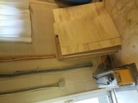
Picked up a 4x8' sheet of 3/4 MDF and 2x sheets of 1/4 sanded plywood earlier this week and this morning I broke it down into slightly oversized pieces that will be more manageable to put through the tablesaw for final dimensioning.
Err...sorry about the rotated photo. If i was on my PC I'd figure out how to fix it
The rest of the afternoon is going to be spent finishing up the rebuild on my 300ZX's transmission, but if that goes well I'll stat fab work on the enclosures tomorrow 🙂
Err...sorry about the rotated photo. If i was on my PC I'd figure out how to fix it
The rest of the afternoon is going to be spent finishing up the rebuild on my 300ZX's transmission, but if that goes well I'll stat fab work on the enclosures tomorrow 🙂
Attachments
Your speaker your decision. I won't get butt hurt if you don't agree.
Since only the woofer is truncated...
It is my OPINION (totally worthless) that if you rotated the woofer 90* the truncated frame would appear to be like that to make the baffle narrower. And therefore blend better with the other drivers.
Since only the woofer is truncated...
It is my OPINION (totally worthless) that if you rotated the woofer 90* the truncated frame would appear to be like that to make the baffle narrower. And therefore blend better with the other drivers.
Troystg - interesting you mention that, as I had considered it myself but every photo of a truncated frame driver was mounted as I have it (perhaps I didn't look hard enough.
Mounted as I have it, center to center distance is reduced. Rotating it would allow a narrower baffle and potentially better baffle diffraction characteristics.
I think I'll explore the pros/cons a bit more before I cut the recesses and facets
Thanks!
Mounted as I have it, center to center distance is reduced. Rotating it would allow a narrower baffle and potentially better baffle diffraction characteristics.
I think I'll explore the pros/cons a bit more before I cut the recesses and facets
Thanks!
It's a can of worms to make a broad determination on that topic. For example some would say the opposite.and potentially better baffle diffraction characteristics.
It can be simplified though. Rounding the front edges with a sufficient radius removes the sharp edge.
You're making saw dust already! Excellent 😀
I didn't want the project to drag out in the "design " phase searching for perfection and never make any project.
At this point im confident that I can make the mid and woofer play nice, and by putting in the oval recess for the waveguide I have flexibly with tweeter selection if needed. The enclosure is sized well for my woofer, so making sawdust forces me to the next phase 😀
With COVID limiting my travel out of the house, now is the perfect time to spend the time needed to make these come out properly!
- Home
- Loudspeakers
- Multi-Way
- My long overdue 3-way tower build