Waiting to see directivity of the system. I have ordered same SB tweeteers to play without waveguide in my long overdue project. The package is unfortunately fmissed somewhere in Europe, 3 weeks from sending now...
Avalanche AS1 modernization
January -19
Avalanche AS1 modernization
January -19
Last edited:
Check back in a couple weeks. I'm hoping to get x-over parts ordered this weekend, so initial system measurements will hopefully be the following weekend.
Btw - this is my first time taking FR measurements, so if anything looks grossly incorrect, I'm open for feedback. I know my measurement setting isn't ideal, but it's what I have to work with
Btw - this is my first time taking FR measurements, so if anything looks grossly incorrect, I'm open for feedback. I know my measurement setting isn't ideal, but it's what I have to work with
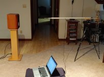
you can remove some of the high frequency hash from your FR response if you insert your mic into a 24 inch length of PVC pipe. Your mic is probably 1 inch OD, so get some 1 inch ID pipe. Chamfer or round the outer edge of the pipe so the transition from mic housing to pipe is smooth. Tape it all together... viola you have a very low reflectivity mic stand for $5 and 45 minutes of your time.
I did it wrong for a while until I found this
Loudspeaker Measurements
my measurements became A LOT smoother after I started using the PVC pipe. My measurements look like I have applied smoothing even with none applied.
I did it wrong for a while until I found this
Loudspeaker Measurements
my measurements became A LOT smoother after I started using the PVC pipe. My measurements look like I have applied smoothing even with none applied.
hifijim - Thanks for the photo, I was having a hard time envisioning what you were describing initially. Thanks! I'll give this a try next time.
Curious - what measurement setup (software & hardware) do you use?
Curious - what measurement setup (software & hardware) do you use?
I use Omnimic. I bought Omnimic and DATSv3 as a package deal from Parts Express… I was looking for a turn-key measurement tool with little learning curve.
I think REW is just as powerful from what I have seen, and it is free. However, I did not want to be burdened with putting together various pieces of hardware, drivers, and software, and then trying to figure out how to integrate them together. I had been away from DIY speaker building for almost 20 years, and I was very focused at the time on acoustics theory, filter theory, and catching up on 20 years of speaker design advancement.
ARTA is another level up in sophistication, but as with any tool, the more sophisticated and powerful, the more time must be invested in order to use it properly.
That looks like a very interesting setup. Not a bad price at all for plug-and-play. Might consider it if I get involved in additional designs in the future
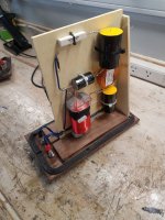
I use my wife's old camera tripod and rigged up a bracket for the pvc pipe... then drilled a 1/2 inch hole in the pipe to run the USB cable out.
The truly correct way to do FR measurements is with a 2-channel audio interface for the mic instead of a USB mic. This way the software has total control over the timing. With Omnimic and other USB microphones, we have to use a work-around method to measure driver delay.
The truly correct way to do FR measurements is with a 2-channel audio interface for the mic instead of a USB mic. This way the software has total control over the timing. With Omnimic and other USB microphones, we have to use a work-around method to measure driver delay.
Did a bit of finishing work last night and today, including a dry-run on a painting procedure (on scraps) and a bit of work on the walnut trim
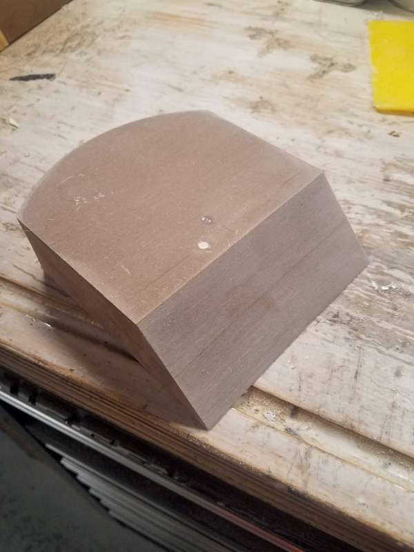
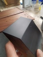
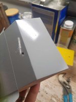
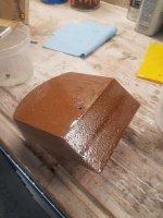
I found one of the "cookies" of double-up MDF left from when I routed the woofer holes. I've always struggled to keep MDF joints from telegraphing through paint, so I used this as a test sample. I squared it up and cut a nice 45 miter on it, then painted it with a coat of epoxy resin, in hopes that it would seal the MDF well.

Sanded with 80 and 120:
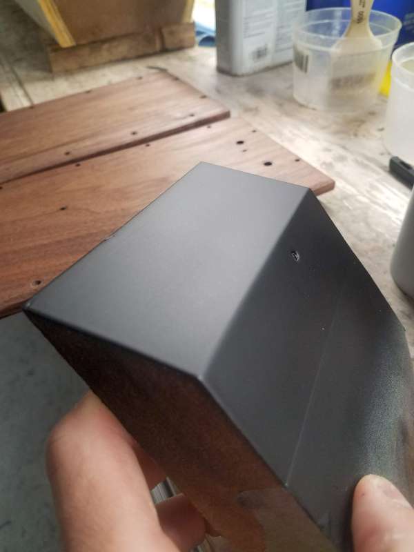
One coat of primer, no signs of a joint!

After 3 coats of primer and 3 coats of satin black. I'm happy!
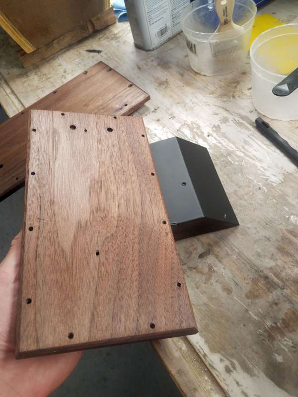
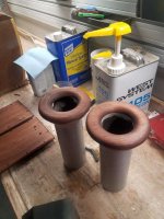
Sanded the walnut x-over covers and port rings w/ 80, 120, 220, and then applied a coat of Tung oil. I wetsanded with the tung oil with 400 to let the sanding dust fill the grain, in hopes of getting it to 'pop' some.
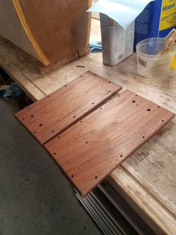

and a side-by side to get an idea of how the contrast will look:
I found one of the "cookies" of double-up MDF left from when I routed the woofer holes. I've always struggled to keep MDF joints from telegraphing through paint, so I used this as a test sample. I squared it up and cut a nice 45 miter on it, then painted it with a coat of epoxy resin, in hopes that it would seal the MDF well.
Sanded with 80 and 120:
One coat of primer, no signs of a joint!
After 3 coats of primer and 3 coats of satin black. I'm happy!
Sanded the walnut x-over covers and port rings w/ 80, 120, 220, and then applied a coat of Tung oil. I wetsanded with the tung oil with 400 to let the sanding dust fill the grain, in hopes of getting it to 'pop' some.
and a side-by side to get an idea of how the contrast will look:
Attachments
-
 20201010_185200-800.jpg50 KB · Views: 285
 -
 20201010_185117-800.jpg51.4 KB · Views: 280
 -
 20201010_185110-800.jpg49.1 KB · Views: 277
 -
 20201010_185125-800.jpg28 KB · Views: 283
 -
 20201010_120038-800.jpg28.7 KB · Views: 292
 -
 20201010_104706-800.jpg38 KB · Views: 295
 -
 20201009_171151-800.jpg45.9 KB · Views: 278
Did some initial x-over sims. I explored two different architectures:
From my first demo listen, I really liked the tonal quality of the midrange, so my initial instinct was to spread the crossover points out a bit, however it seems like the 2000hz crossover point may result in a minor depression around 2khz, whereas the lower 1600hz crossover points seems a bit flatter in this range. Tweeter looks like it might need a bit of attenuation at the top end on-axis.
Next step is to look a bit closer at off-axis response and phase. I might place an order for parts for both upper x-over point options along with a couple l-pad levels.
200/1600hz up top, 200/2000hz on the bottom. Lower end of the woofer is really poor resolution because the sim wants to pull in the farfield off-axis instead of the spliced nearfield/farfield data. Any thoughts on how the response is looking or on my initial x-over points and slopes?
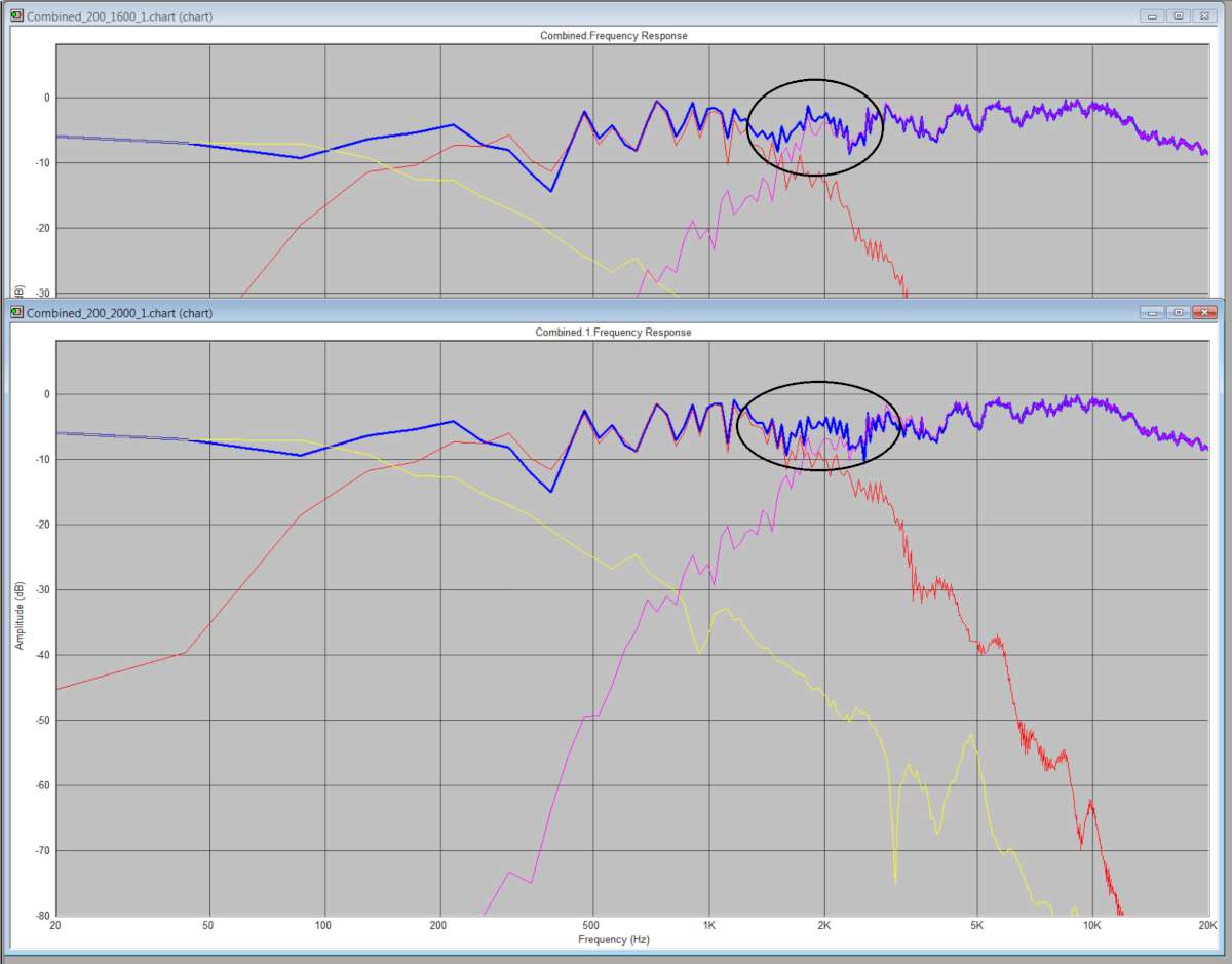
- woofer/mid - 200hz, 2nd order LR; mid/tweeter - 1600hz, 4th order LR (3octave separation)
- woofer/mid - 200hz, 2nd order LR; mid/tweeter - 2000hz, 4th order LR (3.4octave separation
From my first demo listen, I really liked the tonal quality of the midrange, so my initial instinct was to spread the crossover points out a bit, however it seems like the 2000hz crossover point may result in a minor depression around 2khz, whereas the lower 1600hz crossover points seems a bit flatter in this range. Tweeter looks like it might need a bit of attenuation at the top end on-axis.
Next step is to look a bit closer at off-axis response and phase. I might place an order for parts for both upper x-over point options along with a couple l-pad levels.
200/1600hz up top, 200/2000hz on the bottom. Lower end of the woofer is really poor resolution because the sim wants to pull in the farfield off-axis instead of the spliced nearfield/farfield data. Any thoughts on how the response is looking or on my initial x-over points and slopes?
Attachments
Check back in a couple weeks. I'm hoping to get x-over parts ordered this weekend, so initial system measurements will hopefully be the following weekend.
Btw - this is my first time taking FR measurements, so if anything looks grossly incorrect, I'm open for feedback. I know my measurement setting isn't ideal, but it's what I have to work with
Your XO work would be so much easier if you could take your measurements outdoors in a reflection free environment. Indoors do what you can to reduce reflections with padding or lower their frequency by simply pulling speaker further into the room or finding a larger room to measure in.
I thought of moving them outside, but I have ton of birds, dogs, etc around me that I thought would corrupt the measurements. I'll try your tips when I measure the initial system.
So i started looking deeper into the cap/inductor values that resulted from optimizing for the desired acoustic slopes, and I'm seeing some unexpectedly high capacitor values. I'll post the schematic for critique later, but in the mean time...
My mid and woofer are 8ohm and the tweeter is 4ohm. Is there anything off-the-bat that I need to do to level out the impedances before optimizing component values?
Quick answer is put 4 ohm R in series with tweeter. But you also need to match sensitivity so that R will become a voltage divider
That simple, ey? Go figure! So basically the 4ohn is the starting point for the series L-pad resistor. Time to do some tweaking
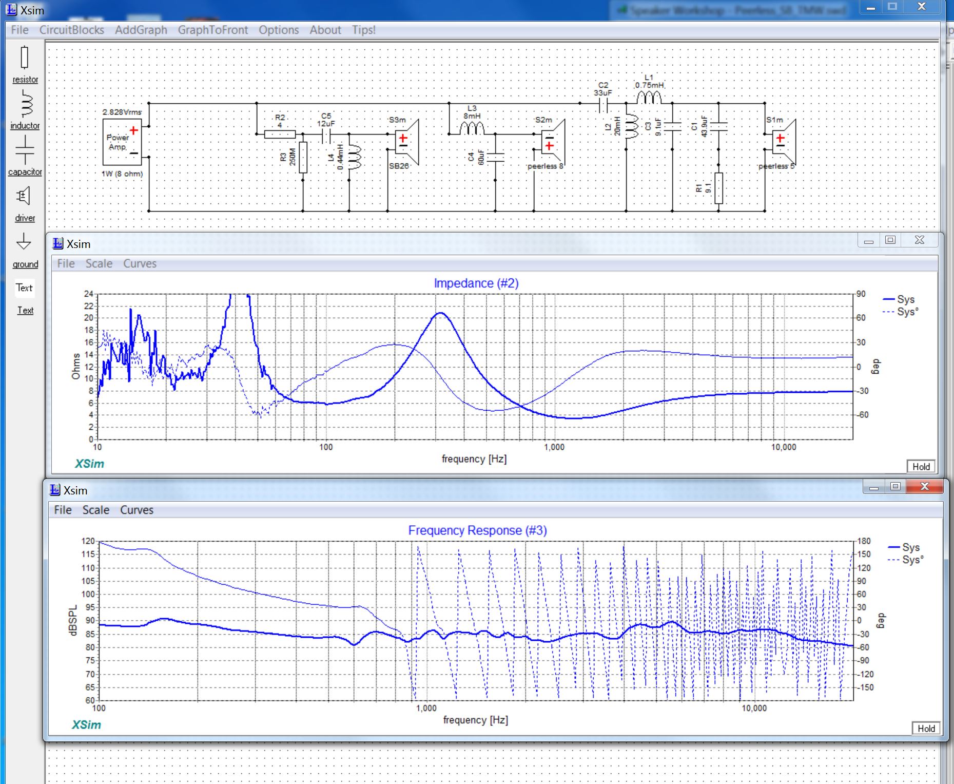
I'm using the crossover design tool in Speaker Workshop. I might give xsim or vituix a shot to see if it's more streamlined and user friendly.
I've never used speaker workshop but it looks like a good basic program. Vituix is more advanced but its got so much in it, it takes a while to absorb.
The reason I asked though is that impedance issues are a lot easier to view and solve in crossover program/simulation.
The reason I asked though is that impedance issues are a lot easier to view and solve in crossover program/simulation.
For kicks I gave Xsim a shot, and I found it very intuitive. In about 15 minutes I exported my FRD and ZMA files out of Speaker workshop and was able to recreate the network. It doesn't seem to have any of the low-frequency simulation resolution issues that I was seeing in Speaker Workshop.
Anyway, I decided to bump the upper X-over point to 2khz and decrease slopes to 2nd order L-R. Figured I'd keep it simple and increase to 4th order if needed after more testing. The Peerless 8 measured impedance was pretty flat in the 200hz range, so I didn't add any impedance compensation. I did, however, add it to the Peerless 5.
I think it looks pretty good, and worthy of prototyping for testing. Thoughts? I plan on ordering parts for 1, 2, and 3db l-pads to allow tweaking of tweeter level. (also, yes, I know I need to adjust a couple values based on availability of real parts 🙂)
Attachments
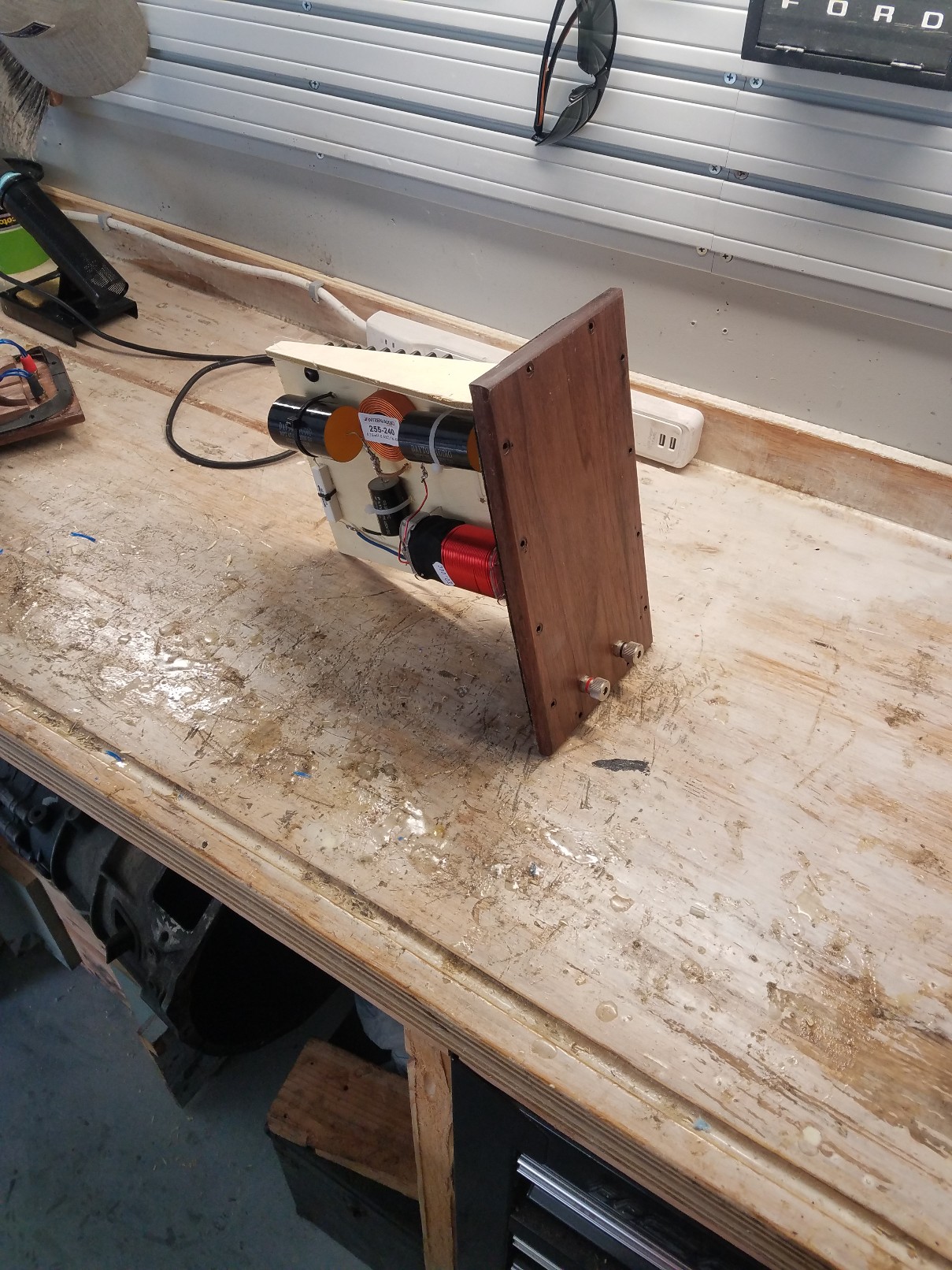
Well I ended up pulling the trigger on the crossover design above. I forgot how big and expensive caps and coils get when you cross at 200hz😱
Crossover assembled. Woofer LP and Tweeter HP on one side, bandpass on the mid on the other:

Time to start sanding:
Crossover assembled. Woofer LP and Tweeter HP on one side, bandpass on the mid on the other:
Time to start sanding:
Attachments


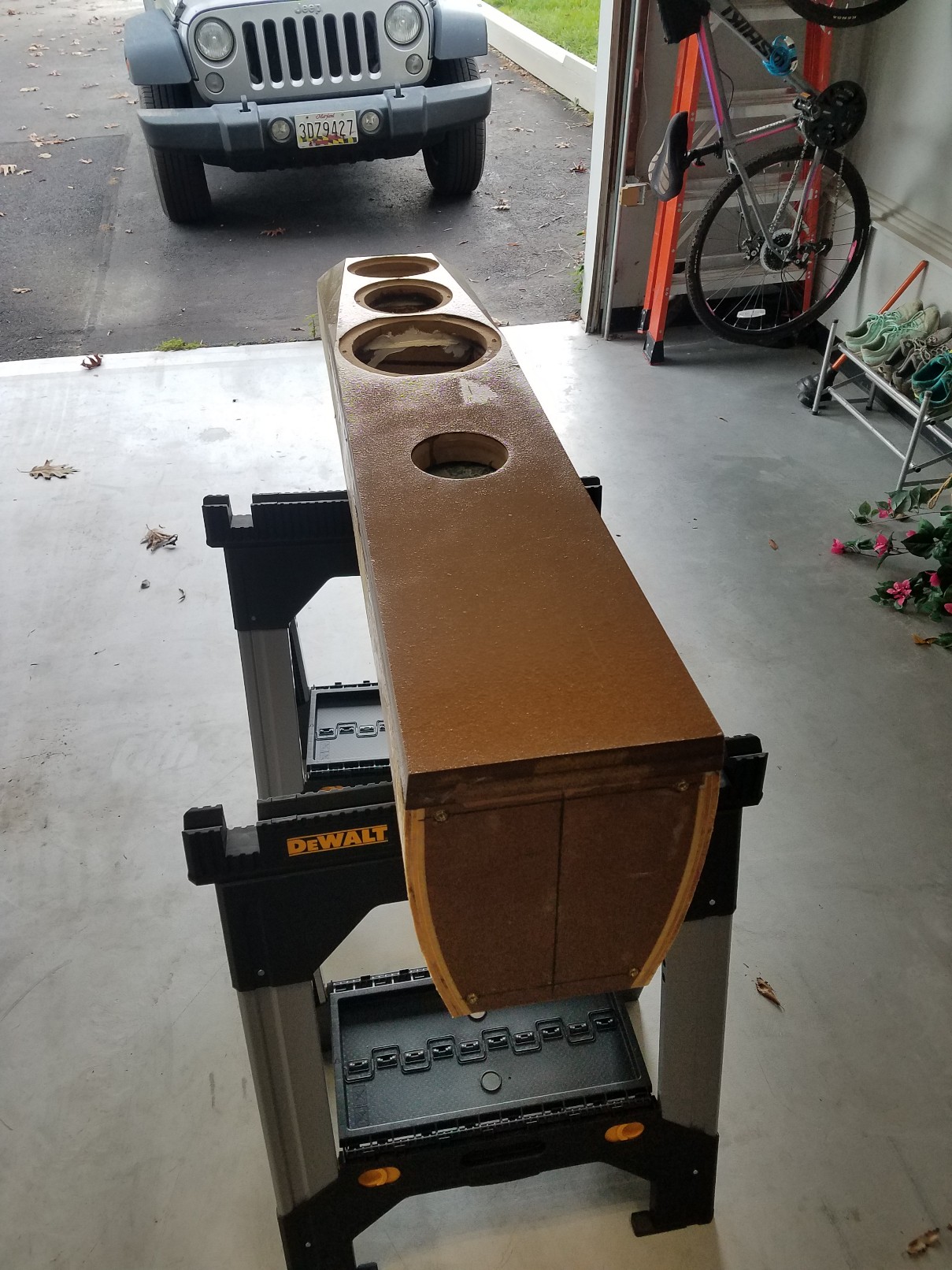
Ended up having to use a lot more filler on the sides than I expected to correct the bellying on the sides, but after 4 days of on-and-off work, they're finally sanded out to 220 and ready for primer.
Wiped them down with mineral spirits tonight to give them plenty of time to dry. Tomorrow I'll tape off the sides and lay a couple coats of high-build primer on the exposed end-grain that probably has a few pinholes that I missed. Should have color on them this weekend 😀
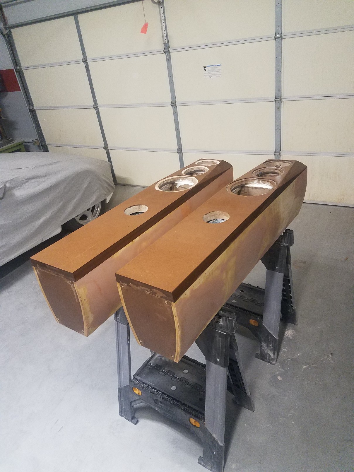
Wiped them down with mineral spirits tonight to give them plenty of time to dry. Tomorrow I'll tape off the sides and lay a couple coats of high-build primer on the exposed end-grain that probably has a few pinholes that I missed. Should have color on them this weekend 😀
Attachments

- Home
- Loudspeakers
- Multi-Way
- My long overdue 3-way tower build