My suggestion was purely for aesthetic reasons.
I don't think the extra inch of distance from the mid will affect the coupling at those frequencies.
As for baffle diffraction I don't have a clue.
But I do like the project!
I don't think the extra inch of distance from the mid will affect the coupling at those frequencies.
As for baffle diffraction I don't have a clue.
But I do like the project!
In three way systems this impedance challenge not only regards the tweeter but also the midrange. But heck, that is what makes speaker design fun.The important thing is that the crossover is actually doing what it should. When a tweeter hits resonance its impedance shoots up. Nominally the tweeter might be 6 ohms and if the crossover is designed to work on that impedance then a massive peak, up to 40 ohms, will significantly alter the way the crossover functions. Instead of the tweeters roll off being a nice smooth, predictable line such as following a typical roll off curve, like a 4th order Linkwitz Riley, you end up with a large discrepancy around resonance and the impedance peak.
The impedance peak usually results in a large peak in output, reducing the crossovers effect and having the tweeter play a lot louder around resonance than it should otherwise be. This not only stresses the tweeter (and sounds bad) but it alters the way the tweeter rolls off and thus alters the way it integrates with the driver below it - this also sounds bad.
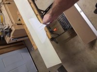
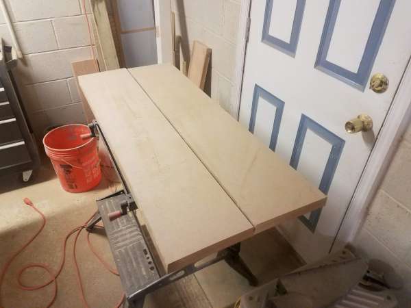
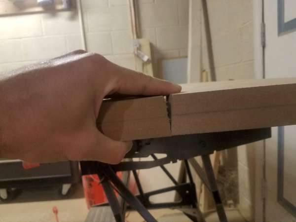
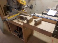
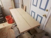
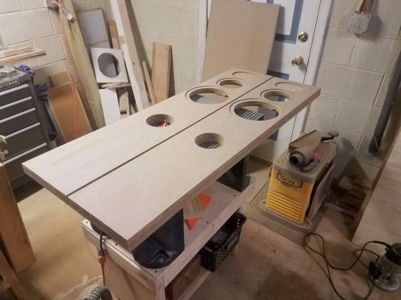
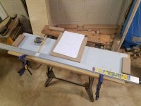
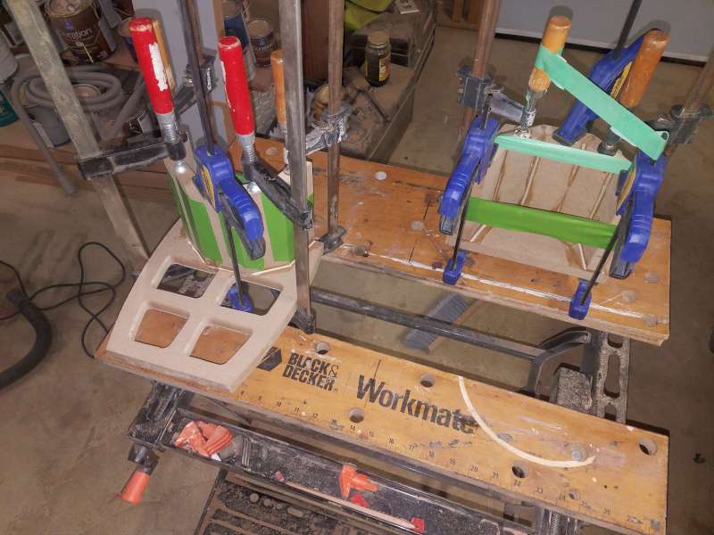
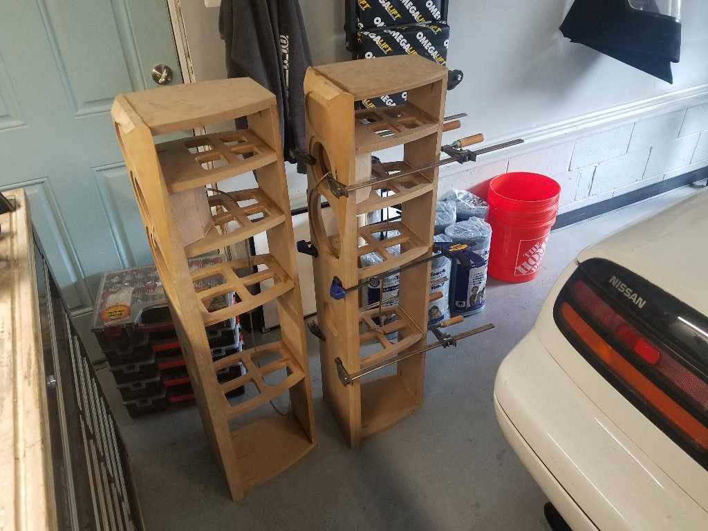
Didn't make anymore sawdust today, but was able to get the baffles glued up. I bought a Kreg Rip-Cut to break down the MDF and plywood into easily workable pieces. Being my first time using it, I left myself an extra 3/4" on the rough-cuts to give myself room to fix any learning mistakes.
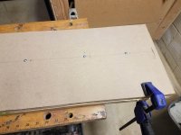
Baffles will be 9 13/16 wide, but I cut four 10 3/4" rips from the 4'x8' sheet. Since the baffle will be the most visible part of the cabinet, I cut a pair from each end to give myself a factory edge on each cabinet to work from. When I laminated them up, I inset the 2nd layer by about 1/16" from the factory edge so that I could easily reference it on the table saw for final dimensioning.
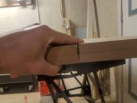
Since I'm limited on clamps, I drilled a few thru-holes in the rear layer to allow myself to drive some Kreg flanged screws into the front layer to provide some additional clamping in the center.
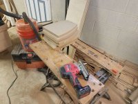
After laying down a bunch of Titebond II on the first layer and realizing I didn't have any disposable paintbrushes to spread it out, I found that a cheapo 12" plastic drywall knife is my new favorite tool for spreading out wood glue:
Some screws in the middle for some additional clamping:
Both baffles stacked on top of each other to allow me to better utilize the clamps I have. I biased the clamps towards the top of the baffle where I'll have multiple driver holes and facets. Hopefully the joints will prove to be tight 🙂
Tomorrow is "cut the grass day" so hopefully I'll have something to share Tuesday or Wednesday.
Baffles will be 9 13/16 wide, but I cut four 10 3/4" rips from the 4'x8' sheet. Since the baffle will be the most visible part of the cabinet, I cut a pair from each end to give myself a factory edge on each cabinet to work from. When I laminated them up, I inset the 2nd layer by about 1/16" from the factory edge so that I could easily reference it on the table saw for final dimensioning.
Since I'm limited on clamps, I drilled a few thru-holes in the rear layer to allow myself to drive some Kreg flanged screws into the front layer to provide some additional clamping in the center.
After laying down a bunch of Titebond II on the first layer and realizing I didn't have any disposable paintbrushes to spread it out, I found that a cheapo 12" plastic drywall knife is my new favorite tool for spreading out wood glue:
Some screws in the middle for some additional clamping:
Both baffles stacked on top of each other to allow me to better utilize the clamps I have. I biased the clamps towards the top of the baffle where I'll have multiple driver holes and facets. Hopefully the joints will prove to be tight 🙂
Tomorrow is "cut the grass day" so hopefully I'll have something to share Tuesday or Wednesday.
Attachments

Resized the photos to 600px wide, hopefully it doesn't give anyone issues. If so I'll just ditch inline photos from here on out😎
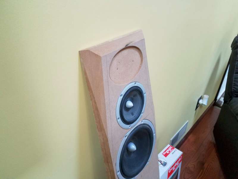
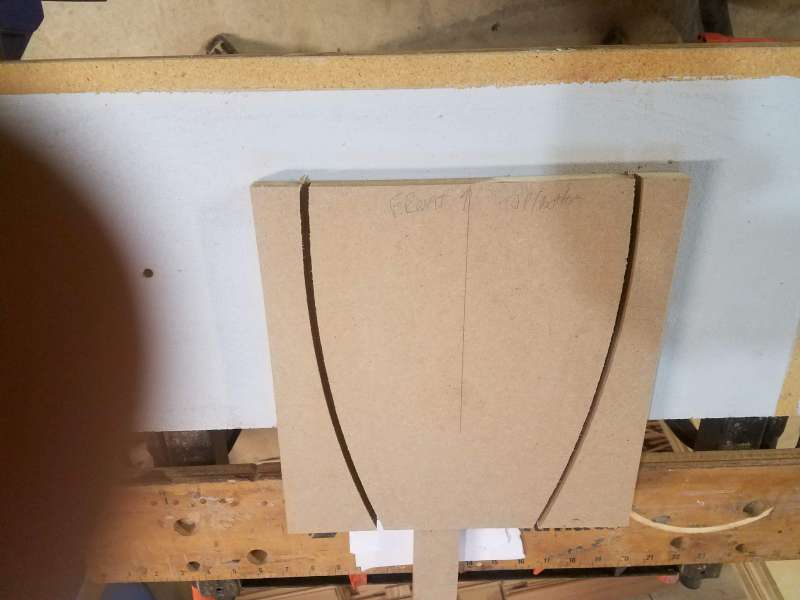
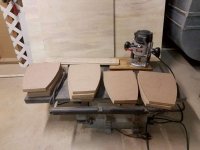
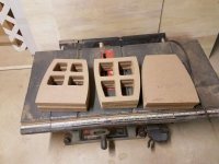
Front baffles cut down to size (9 13/16 wide x 47.5 high, 5.5° chamfer to blend with the curved sides:
...and got the mitered pieces for the mid enclosures cut. I first ripped a pair of ~30" long strips on my table saw w/ the blade set at 18°, then cut them down to 5.625" on the miter saw:


Next up is the back. It's been a while since I worked w/ MDF. I forgot how much I hate it 😱 I'll be upgrading my dust collection before I take on another MDF based project.
Front baffles cut down to size (9 13/16 wide x 47.5 high, 5.5° chamfer to blend with the curved sides:
...and got the mitered pieces for the mid enclosures cut. I first ripped a pair of ~30" long strips on my table saw w/ the blade set at 18°, then cut them down to 5.625" on the miter saw:
Next up is the back. It's been a while since I worked w/ MDF. I forgot how much I hate it 😱 I'll be upgrading my dust collection before I take on another MDF based project.
Attachments

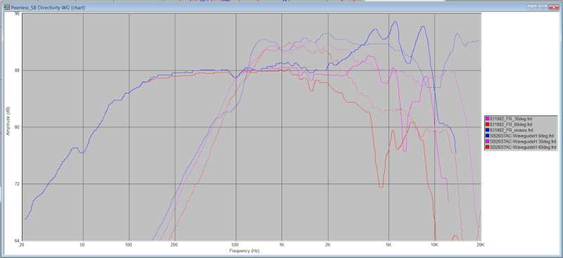
Last week I did some work tracing in FR charts from augerpro's SB26 waveguides and comparing them to my current Daytons. I've decided that the Daytons really are a bit too "low-budget" for the amount of work I'm going to put into these. I think I'll save the Datyons for another project. Perhaps a pair of rear surround speakers for the room.
Made some more sawdust yesterday. Finally done with the tablesaw, so hopefully I can stick to tools that have integrated dust collection to keep the mess down 🙂
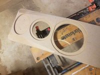
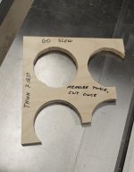
Next up is routing the recesses for the truncated frame 8s and then starting to make templates for the internal braces and dividers.
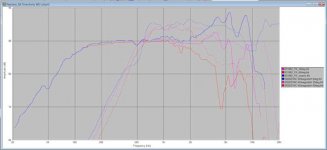
First, a comparison of my Dayton tweeters to the SB26s. Daytons are in light blue, stock SB26STACs are in dark blue, SB26STAC w/ augerpro's version H 5" waveguides are in red. The SB26s extend ~1khz lower cleanly and have a much smoother response, and for $40 each look to be an affordable, significant upgrade. I'm not dead set on these specific tweeters yet, as I will be making FR measurements of the peerless drivers installed in the cabinets before I make final tweeter decisions. If I end up not utilizing a waveguide, I can easily make a cosmetic filler plate to bridge between the selected tweeter and the recess that I've routed.
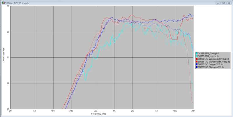
Overlay of the 0°/30°/60° FR plots of the peerless mid and SB26STAC w/ waveguide. Blue = on-axis, magenta is 30°, Red is 60°. Solid trace is the mid, dashed is the tweeter. If you were to attenuate the tweeter response appropriately, the off-axis rolloff looks like it would match that of the mid fairly well.
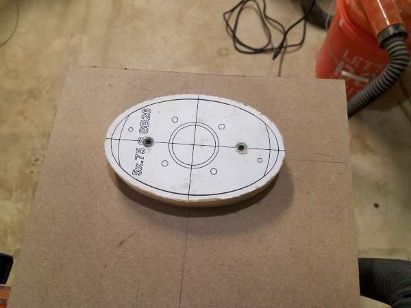
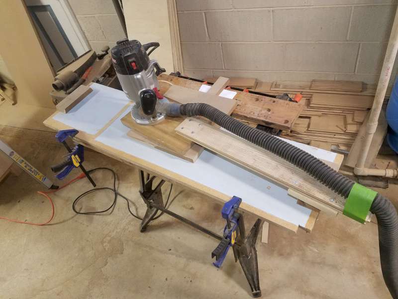
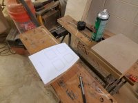
To make my pattern for routing the waveguide recess I brought the waveguide STEP file into CAD, made a 2D drawing, and then offset the perimeter inwards by 5/16" to account for the pattern bushing/bit offset. I rough-cut the perimeter and then sanded down to the dashed line. I aligned the crosshairs of the printout with the layout lines on the baffle, and then screwed the template down in a location that will be routed away anyway.
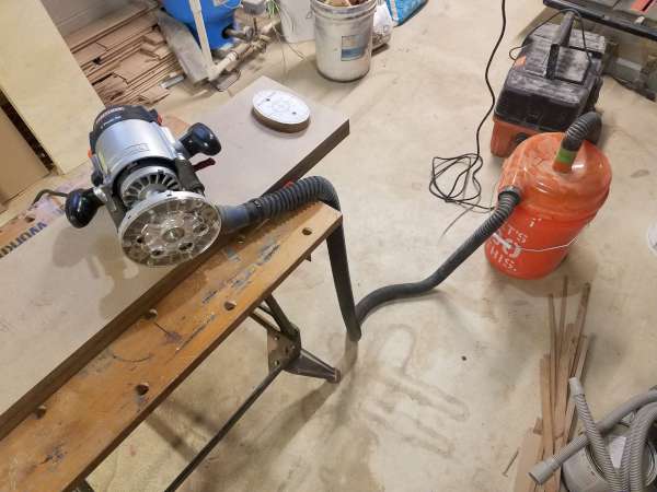
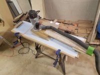
My budget dust-collection system. Works well enough, but more CFM would help. I plan to replace this with a wall-mounted Rinkon unit when time/budget permits
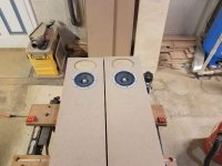
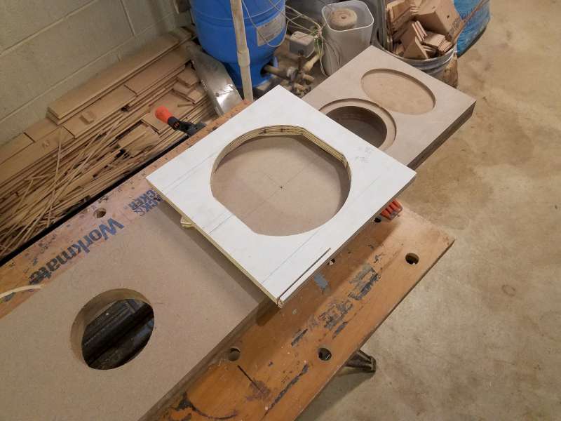
Perimeter routed. I cleared out the rest of the middle by hand.

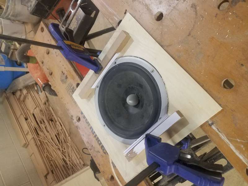
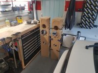
Mid recess routed using my trusty Jasper Jig. Drivers fit like a glove:

Made some more sawdust yesterday. Finally done with the tablesaw, so hopefully I can stick to tools that have integrated dust collection to keep the mess down 🙂
- Cabinet backs are cut (no photos, rectangular strips of MDF aren't that exciting...
- I made a template for the 5" waveguide that augerpro has designed for the SB26 tweeters
- Used a 1/4" upcut spiral bit and 3/8" templating bushing to route the recess for the waveguide
- Routed the cutout for the 5" Peerless mids and test-fit them
Next up is routing the recesses for the truncated frame 8s and then starting to make templates for the internal braces and dividers.
First, a comparison of my Dayton tweeters to the SB26s. Daytons are in light blue, stock SB26STACs are in dark blue, SB26STAC w/ augerpro's version H 5" waveguides are in red. The SB26s extend ~1khz lower cleanly and have a much smoother response, and for $40 each look to be an affordable, significant upgrade. I'm not dead set on these specific tweeters yet, as I will be making FR measurements of the peerless drivers installed in the cabinets before I make final tweeter decisions. If I end up not utilizing a waveguide, I can easily make a cosmetic filler plate to bridge between the selected tweeter and the recess that I've routed.
Overlay of the 0°/30°/60° FR plots of the peerless mid and SB26STAC w/ waveguide. Blue = on-axis, magenta is 30°, Red is 60°. Solid trace is the mid, dashed is the tweeter. If you were to attenuate the tweeter response appropriately, the off-axis rolloff looks like it would match that of the mid fairly well.
To make my pattern for routing the waveguide recess I brought the waveguide STEP file into CAD, made a 2D drawing, and then offset the perimeter inwards by 5/16" to account for the pattern bushing/bit offset. I rough-cut the perimeter and then sanded down to the dashed line. I aligned the crosshairs of the printout with the layout lines on the baffle, and then screwed the template down in a location that will be routed away anyway.
My budget dust-collection system. Works well enough, but more CFM would help. I plan to replace this with a wall-mounted Rinkon unit when time/budget permits
Perimeter routed. I cleared out the rest of the middle by hand.
Mid recess routed using my trusty Jasper Jig. Drivers fit like a glove:
Attachments


Made some more sawdust today:
Tomorrow I'm hoping to route out the template for the top/bottom/divider panels and get most (if not all) of them cut.
Here's the jig I made for routing the recesses for the truncated frame 8's. I routed a hole in 1/4" plywood that was a 1/16" larger than the OD of the speaker. After centering it around the speaker, I glued some strips of MDF onto the 1/4" plywood spaced away from the flats of the speaker by 0.016" (4 sheets of paper). I then used this temporary template to transfer the pattern to 3/4" plywood to make a final template. After attaching the final template to the face of the baffle with double-sided tape, I routed the recess with a top-bearing pattern bit like this.
Finshed 8" cutouts:
I had to adjust the long side facets a bit, as I realize that they were 35° below horizontal (which my saw can't do), not 35° off vertical. I'm still happy with how they came out. I might see if I can figure out a way to tilt the baffles up 10° to let me chamfer them how I had planned, but that will depend on how well I make out tomorrow with the top/bottom/divider fabrication.
And a quick preview of how they'll fit in their future home:
- Front Baffles are complete, minust the tweeter thru-hole
- I squared up MDF blanks for the top and bottom panels, which will also become templates for interior bracing and dividers
Tomorrow I'm hoping to route out the template for the top/bottom/divider panels and get most (if not all) of them cut.
Here's the jig I made for routing the recesses for the truncated frame 8's. I routed a hole in 1/4" plywood that was a 1/16" larger than the OD of the speaker. After centering it around the speaker, I glued some strips of MDF onto the 1/4" plywood spaced away from the flats of the speaker by 0.016" (4 sheets of paper). I then used this temporary template to transfer the pattern to 3/4" plywood to make a final template. After attaching the final template to the face of the baffle with double-sided tape, I routed the recess with a top-bearing pattern bit like this.
Finshed 8" cutouts:
I had to adjust the long side facets a bit, as I realize that they were 35° below horizontal (which my saw can't do), not 35° off vertical. I'm still happy with how they came out. I might see if I can figure out a way to tilt the baffles up 10° to let me chamfer them how I had planned, but that will depend on how well I make out tomorrow with the top/bottom/divider fabrication.
And a quick preview of how they'll fit in their future home:
Attachments


Last edited:
Wow things are really coming along! Love seeing the process and how you're approaching making the waveguide etc. It's good food for thought for others considering going the same route.
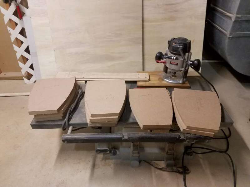
Nothing feels quite like a good shower after making MDF dust for ~5 hours😎 Gave the jigsaw, router table, pattern bit, and shop-vac a hard workout today and got all of the horizontal pieces made:
All 8 pieces share the same width at the front, same side curvature, but the top & bottom are 3/4" deeper. I'm really happy with how the outer profile of them came out....very consistent and the couple measurements I took suggest that the curvature came out accurate within about 1/32". The cutouts for the bracing came out a bit more jagged than I had hoped, and I'll attribute that to me getting used to my new Milwaukee jigsaw combined with a flimsy blade that was walking a bit. I guess using my dad's Bosch spoiled me 🙁
First step was to make a jig to cut the side curvature onto one of the blanks that I had previously made. Note: I ended up using 3M VHB double-sided tape for just about everything you see her, including mounting the 3 pieces of MDF to the jig and attaching the patterns to the blanks. It's not cheap stuff, but it really works great.
To make the jig I first found a scrap board ~40" long and clamped a straight edge to it. I marked the centerline of blank cutout, aligned it onto the straight-egdge, and mounted it with VHB. I then mounted two scraps of MDF ~ 20.5" to the left and right of the blank's centerline, again aligning them to the straight edge and mounting with VHB. The centerpoints of the arc were 20.625" to either side of the centerline and 2.5" back from the front edge, so I marked both centers and drilled an 1/8" dowel-pin hole. I then fabbed up an extended circle jig for my router and drilled another 1/8" pilot hole 25" from the inner edge of the bit. I removed the straight edge and then routed the left and right curves, stopping ~1/16" short of cutting through. After cutting the scrap free with a jigsaw, I finished the last 1/16" on the router table.
Blank and both pivot points mounted along the straightedge:

Extended circle jig fabbed out of a scrap of poplar and a scrap piece of oak flooring:
Routed and ready to trim:
Stack of blank rough-cut with my jigsaw:

Blanks trimmed using the first one as a template:
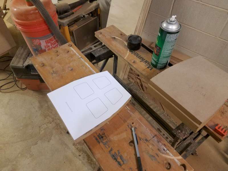
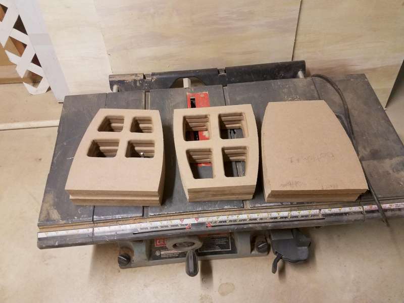
1:1 printout of the openings for the midrange enclosure/divider tacked down w/ 3M super 90 spray adhesive. After cutting this one w/ the jigsaw, I used it as a template to route the venting on the other 3. I used the same technique for the 4 lower braces:
End result of the day's work:
I think I figured out how to jig-up the front baffles to get the extra 10° of bevel on the facets, so I'm going to tackle that next. Once that is done, It's time to start assembling 🙂
- 2x Top
- 2x Bottom
- 4x Midrange enclosure floor/ceiling (2 per cabinet)
- 4x Cross-braces (2 per cabinet)
All 8 pieces share the same width at the front, same side curvature, but the top & bottom are 3/4" deeper. I'm really happy with how the outer profile of them came out....very consistent and the couple measurements I took suggest that the curvature came out accurate within about 1/32". The cutouts for the bracing came out a bit more jagged than I had hoped, and I'll attribute that to me getting used to my new Milwaukee jigsaw combined with a flimsy blade that was walking a bit. I guess using my dad's Bosch spoiled me 🙁
First step was to make a jig to cut the side curvature onto one of the blanks that I had previously made. Note: I ended up using 3M VHB double-sided tape for just about everything you see her, including mounting the 3 pieces of MDF to the jig and attaching the patterns to the blanks. It's not cheap stuff, but it really works great.
To make the jig I first found a scrap board ~40" long and clamped a straight edge to it. I marked the centerline of blank cutout, aligned it onto the straight-egdge, and mounted it with VHB. I then mounted two scraps of MDF ~ 20.5" to the left and right of the blank's centerline, again aligning them to the straight edge and mounting with VHB. The centerpoints of the arc were 20.625" to either side of the centerline and 2.5" back from the front edge, so I marked both centers and drilled an 1/8" dowel-pin hole. I then fabbed up an extended circle jig for my router and drilled another 1/8" pilot hole 25" from the inner edge of the bit. I removed the straight edge and then routed the left and right curves, stopping ~1/16" short of cutting through. After cutting the scrap free with a jigsaw, I finished the last 1/16" on the router table.
Blank and both pivot points mounted along the straightedge:
Extended circle jig fabbed out of a scrap of poplar and a scrap piece of oak flooring:
Routed and ready to trim:
Stack of blank rough-cut with my jigsaw:
Blanks trimmed using the first one as a template:
1:1 printout of the openings for the midrange enclosure/divider tacked down w/ 3M super 90 spray adhesive. After cutting this one w/ the jigsaw, I used it as a template to route the venting on the other 3. I used the same technique for the 4 lower braces:
End result of the day's work:
I think I figured out how to jig-up the front baffles to get the extra 10° of bevel on the facets, so I'm going to tackle that next. Once that is done, It's time to start assembling 🙂
Attachments
-
 20200809_110319-800.jpg32.8 KB · Views: 487
 -
 20200809_105653-800.jpg49.2 KB · Views: 488
 -
 20200809_100621-800.jpg45.3 KB · Views: 486
 -
 20200809_115556-800.jpg55.7 KB · Views: 484
 -
 20200809_122539-800.jpg35.3 KB · Views: 490
 -
 20200809_124415-800.jpg46.1 KB · Views: 482
 -
 20200809_152311-800.jpg41.8 KB · Views: 485
Only spent an hour or so working on them this weekend, but cleared the way for some very satisfying progress during the week if I can find a few hours to spare.
Side facets cut. The travel of my saw came up about an inch short of making the full cut, but a sanding block will make quick work of the bit of uncut area that is adjacent to the 8" cutout.

Mid enclosures glued up. 2" wide Frog Tape worked really well for holding the miters together.
I'll leave these clamped up for the next couple days and hopefully Tuesday or Wednesday night I'll be able to start gluing up the enclosures 🙂
- After cutting some 10° angle blocks, I fixtured up the baffles on my miter saw and cut the bevels to the 55° anlge that I had originally planned.
- I glud up the midrange enclosure backs and glued them to the lower enclosure divider
Side facets cut. The travel of my saw came up about an inch short of making the full cut, but a sanding block will make quick work of the bit of uncut area that is adjacent to the 8" cutout.
Mid enclosures glued up. 2" wide Frog Tape worked really well for holding the miters together.
I'll leave these clamped up for the next couple days and hopefully Tuesday or Wednesday night I'll be able to start gluing up the enclosures 🙂
Attachments

I've picked up a number of useful fabrication techniques from reading detailed build threads, so I like to try and return the favor, even if it's showing what not to do!
That's a neat "reminder". I bought my dad a shirt for father's day a few years ago that says "Measure twice, cut once. Curse. Buy more wood. Try again"
That's a neat "reminder". I bought my dad a shirt for father's day a few years ago that says "Measure twice, cut once. Curse. Buy more wood. Try again"
Since I'm done cutting wood for now, I move the project from my dungeon-like downstairs backroom out into my garage so that I could spread out on a proper workbench for assembly.
Front baffles, tops, bottoms, and all internal structure laid out:

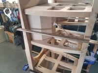
Since I don't have an adequate selection of clamps, I used my Kreg jig to put 1.25" coarse thread Kreg screws from each divider into the front baffle to hold the joint tight after I clamped it in place. Mid enclosure and both lower braces mounted on one cabinet:
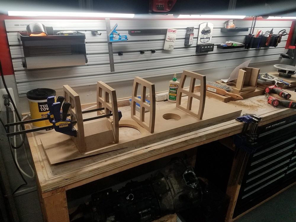
The clearance to the 8" midbass looks tight, and it is. I held my breath but a fit check shows a solid 1/4" of clearance 🙂
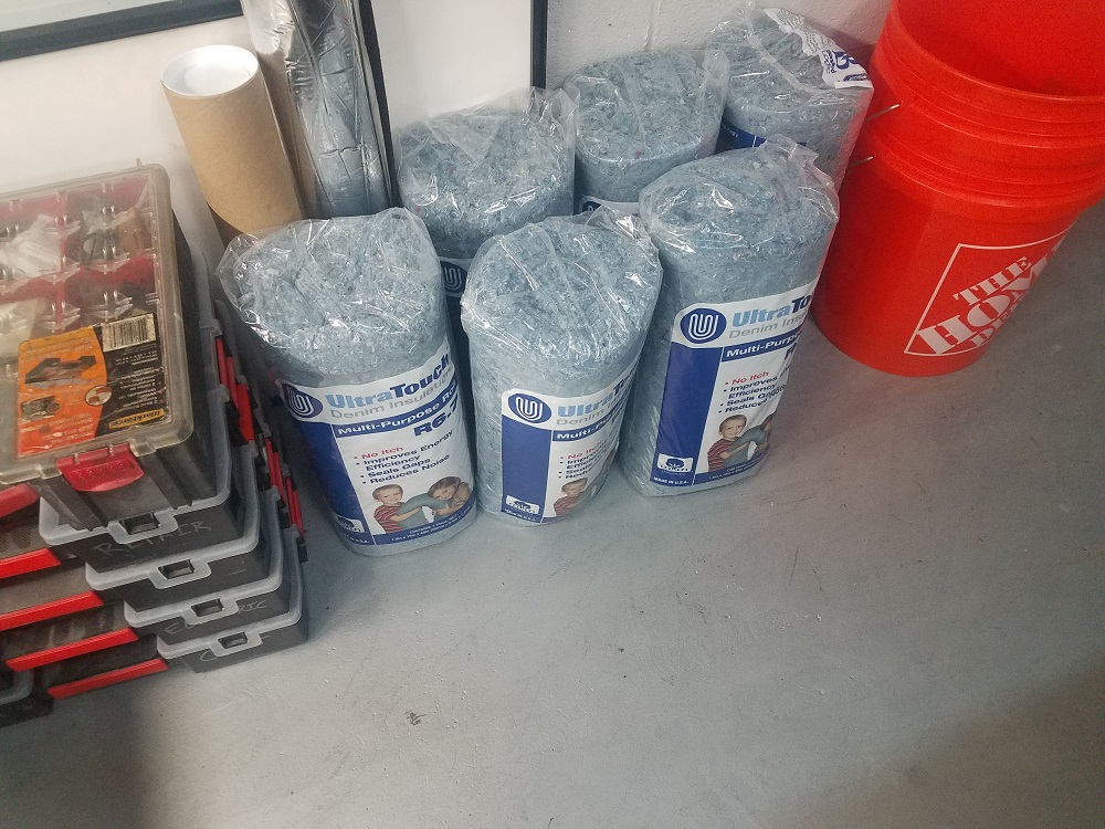
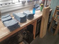
And I picked up the 6 rolls of denim insulation that I ordered to my local Home Depot. Augerpro's Construction Methods Thread shows great performance for the cost, so I figured I'd give it a shot. For the mid enclosure I plan on taking some A/B measurements with the denim insulation and melamine foam just for kicks.
Front baffles, tops, bottoms, and all internal structure laid out:
Since I don't have an adequate selection of clamps, I used my Kreg jig to put 1.25" coarse thread Kreg screws from each divider into the front baffle to hold the joint tight after I clamped it in place. Mid enclosure and both lower braces mounted on one cabinet:
The clearance to the 8" midbass looks tight, and it is. I held my breath but a fit check shows a solid 1/4" of clearance 🙂
And I picked up the 6 rolls of denim insulation that I ordered to my local Home Depot. Augerpro's Construction Methods Thread shows great performance for the cost, so I figured I'd give it a shot. For the mid enclosure I plan on taking some A/B measurements with the denim insulation and melamine foam just for kicks.
Attachments

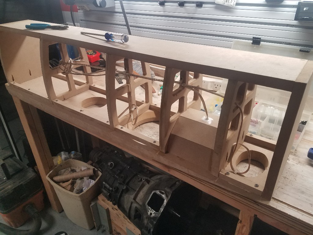
Finished up the "skeleton" of the enclosures today and sealed up the wire pass-thru into the midrange enclosure with 3M 5200 quick cure marine sealant (stuff is great, I use it for everything). If other house chores don't interfere I might get to bust out the epoxy and start laying up the sides tomorrow 🙂


Attachments

Spent the afternoon yesterday making some more assembly process. Routed the internal wiring for the tweeters and 8s, lined the enclosure "skeletons" with denim insulation, cut insulation pieces for the sides, and did a dry run on bending/clamping the first layer of the sides one.
First screwup - grain direction matters
When I ripped the 12 blanks for the enclosure side laminations, I neglected to consider grain direction, leaving me with blanks that need to be bent against the grain instead of with the grain. Not only did this make it very hard to get complete contact between the skin and shelf braces, it left the skin very flimsy in between the braces and resulted in the plywood puckering in by 1/8 - 1/4in in between the braces. Glad I found this out before I mixed resin up. Time to grab more plywood 🙁
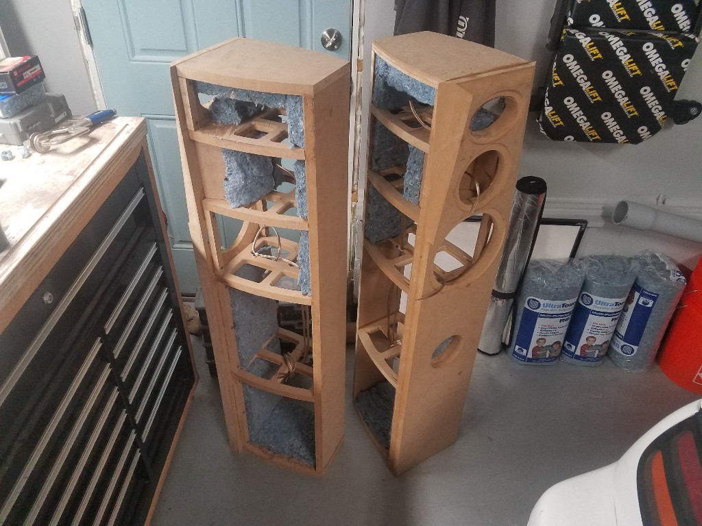

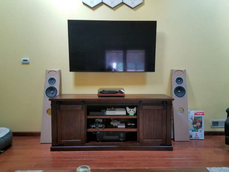
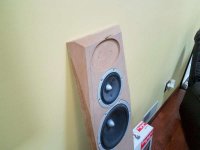
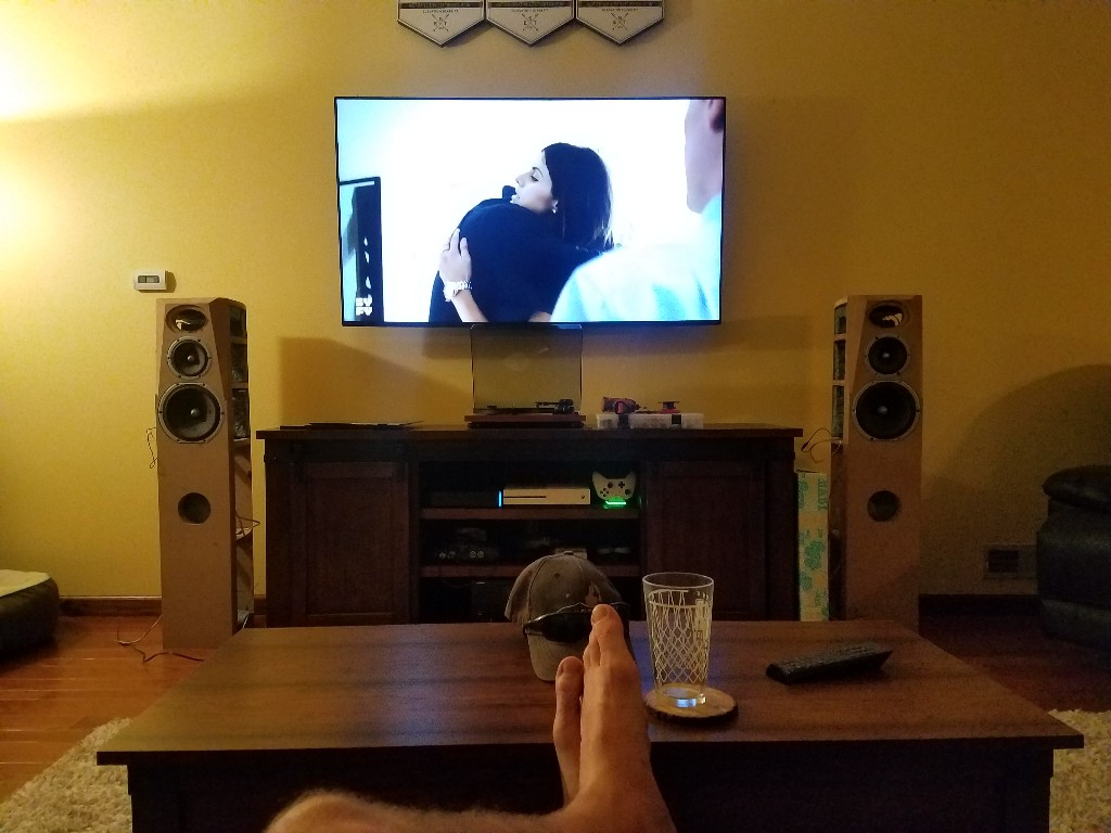
I got eager to get a bit of a reward for my progress, so I moved then into my livingroom for an early demo, one driver at a time. Vocals sound really clean from the mids. The 8s....make sound 😀. I'll be eager to hook them up when the enclosures are done
First screwup - grain direction matters
When I ripped the 12 blanks for the enclosure side laminations, I neglected to consider grain direction, leaving me with blanks that need to be bent against the grain instead of with the grain. Not only did this make it very hard to get complete contact between the skin and shelf braces, it left the skin very flimsy in between the braces and resulted in the plywood puckering in by 1/8 - 1/4in in between the braces. Glad I found this out before I mixed resin up. Time to grab more plywood 🙁
I got eager to get a bit of a reward for my progress, so I moved then into my livingroom for an early demo, one driver at a time. Vocals sound really clean from the mids. The 8s....make sound 😀. I'll be eager to hook them up when the enclosures are done
Attachments


Thanks for the comments! Both cabinets not have one layer of 1/4" ply affixed to the sides. Two more layers per side to go. I just got back from vacation, so I hopefully will be able to make some good progress later this week/weekend.
- Home
- Loudspeakers
- Multi-Way
- My long overdue 3-way tower build