Yamaha RX-V357 amplifier, no display, no diag mode-only power relay toggle click
- By seditiouss
- Chip Amps
- 25 Replies
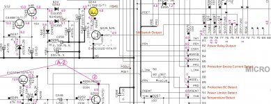
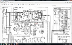
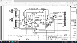
I have an Yamaha RX-V357 that suddenly stopped working , no protection mode , no display , no diag mode - only power relay toggle (clicking on and off).
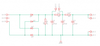
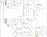
I've already disconnected power stage voltages in order to avoid any output / speaker DC protection and also power relay is by-passed in order to have all voltages ready-to-be-checked from power transformer.
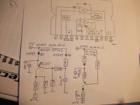
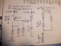
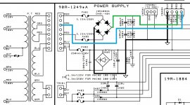
Almost all voltages seem to be correct, except 5MS that missing. If 5MS externally provided no more relay clicking but still no display.
Any help ?
I've already disconnected power stage voltages in order to avoid any output / speaker DC protection and also power relay is by-passed in order to have all voltages ready-to-be-checked from power transformer.
Almost all voltages seem to be correct, except 5MS that missing. If 5MS externally provided no more relay clicking but still no display.
Any help ?


