Hello diyers,
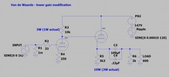
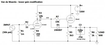
Having a handful of kits under my belt, I am looking to embark upon my first scratch build -- a tube headphone amplifier based on the Van Waarde design, tweaked based on some comments from user audiowize in a thread here, substituting a 5687 tube and tweaking the plate and cathode resistors to reduce the gain.
I am aware of the limitations of OTL tube amplifiers in driving low-impedance headphones; my primary application for this will be driving 600 ohm Beyer DT880’s. I know this isn’t the end-all be-all of designs -- I like that it’s simple, with a relatively low parts count, and seems like a fun first scratch build project.
Here are the design constraints that I’ve set out for myself:
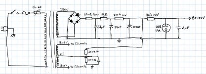
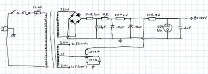
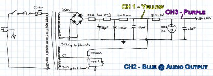
I’ve attached the schematics and a screenshot of the PSU design and single-channel schematic.
I was planning on using the following real-world parts in the power supply:
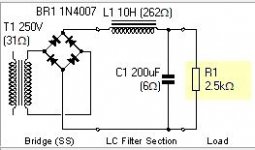
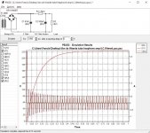
From my simple simulations, it appears that at quiescent current the L-C filter I’ve simulated in front of the 0D3 regulator will reduce the ripple to about 175mV (peak) and the regulator and subsequent 47uF cap will further reduce it to 100uV. (I substituted a Zener in the simulation because I don't have a model for the 0D3/VR150 tube.) The LTSpice sim shows only 45uV on the output.
What does everyone think? Am I missing anything obvious here? Any feedback is welcome. Will post build photos and tests as I progress.
Having a handful of kits under my belt, I am looking to embark upon my first scratch build -- a tube headphone amplifier based on the Van Waarde design, tweaked based on some comments from user audiowize in a thread here, substituting a 5687 tube and tweaking the plate and cathode resistors to reduce the gain.
I am aware of the limitations of OTL tube amplifiers in driving low-impedance headphones; my primary application for this will be driving 600 ohm Beyer DT880’s. I know this isn’t the end-all be-all of designs -- I like that it’s simple, with a relatively low parts count, and seems like a fun first scratch build project.
Here are the design constraints that I’ve set out for myself:
- Single-chassis design, preferably not too large (considering a 10” x 5” x 3” or 9.5” x 5” x 2” Hammond enclosure)
- 0D3/VR150 shunt regulator w/ MOSFET to provide the ~150VDC B+ (I need that beautiful blue glow in my life) based on this circuit and this thread
- Heaters to be run on elevated AC
- Solid state rectification
- Reasonable budget (as always, I have to set aside a large portion of it for new tools 🙂 )
I’ve attached the schematics and a screenshot of the PSU design and single-channel schematic.
I was planning on using the following real-world parts in the power supply:
- Ecdor XPWR262-120 transformer (225VDC @ 300mA w/ 6.3VCT @6A)
- Hammond 158M 10H @ 100mA open-frame choke
From my simple simulations, it appears that at quiescent current the L-C filter I’ve simulated in front of the 0D3 regulator will reduce the ripple to about 175mV (peak) and the regulator and subsequent 47uF cap will further reduce it to 100uV. (I substituted a Zener in the simulation because I don't have a model for the 0D3/VR150 tube.) The LTSpice sim shows only 45uV on the output.
What does everyone think? Am I missing anything obvious here? Any feedback is welcome. Will post build photos and tests as I progress.
Attachments
The FET is going to get pretty hot in that design. You can use the 0D3 and a resistor between the 0D3 and B+ to make a far simpler regulator, but you'd want one 0D3 per channel. You can run the 0D3 at far higher currents for shorter periods of time, so consider 60mA total per channel. This would give you a shunt regulated amp rather than a series regulated amp.
Go for ~220V of B+, then use a 1K 10+W dropping resistor per channel.
The choke input filter is a great way to reduce power transformer AC current and to increase regulation. You probably don't need either of those, so you could opt for a CRC filter and take the reduced ripple instead.
Go for ~220V of B+, then use a 1K 10+W dropping resistor per channel.
The choke input filter is a great way to reduce power transformer AC current and to increase regulation. You probably don't need either of those, so you could opt for a CRC filter and take the reduced ripple instead.
Thanks for the reply.
From what I can see in the sim the total current for both channels should never exceed ~80mA and the quiescent is about ~69mA. I have a chunky TO-220 heatsink leftover from another project I was thinking of using (and I've been recently running some TO-220 MOSFETs at 80mA quiescent current in another headphone amp - they do get hot but I have them chassis-mounted so they dissipate heat pretty well).
That said, I'm sure at turn-on the MOSFET will have to pass a much larger current while the capacitors charge up. Not sure if that's a big concern.
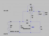
Anyhow, I want to ensure that I'm understanding you correctly. You're suggesting substituting the LC filter for a CRC filter and then using two simple 0D3 shunt regs w/ a series 1K resistor to provide +150VDC B+ to each channel.
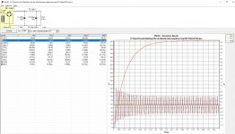
I've simulated CRC filter w/ the 225V 300mA transformer I was planning to use in PSUD. The AC Ip is about 500mA. I'm not certain I properly understand how to judge transformer secondary current ratings. Hammond's design guide states that with a capacitor load the IDC = .062 x Sec. I A.C. If that's based on the quiescent current drawn by the load (amplifier tubes) then we're within that range (less than 186mA). However, if I assume that the waveform in the PSUD simulation is a sine wave then Irms is 336mA -- exceeding the rating.
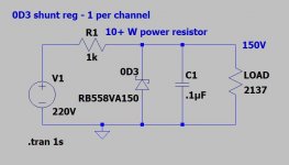
I've also sketched out the simple shunt reg you suggested with the 1K dropping resistor in series with the 0D3. I understand the role of the dropping resistor in terms of protecting the 0D3 from exceeding its maximum current capacity at turn-on -- but at quiescent current (69mA being drawn by the amp) the 0D3 is completely turned off. Only when the load draws more current does the 0D3 conduct. Since the 0D3 requires a minimum of 185VDC to start up, should I not adjust the resistor value to something like 750 ohms thereby feeding 185VDC to the 0D3 at quiescent conditions and allowing it to start up (and conduct ~24mA of current)?
Thanks for the suggestions -- the idea of getting rid of the bulky 10H choke and using two pretty blue tubes instead of just one does appeal to me.
The FET is going to get pretty hot in that design.
From what I can see in the sim the total current for both channels should never exceed ~80mA and the quiescent is about ~69mA. I have a chunky TO-220 heatsink leftover from another project I was thinking of using (and I've been recently running some TO-220 MOSFETs at 80mA quiescent current in another headphone amp - they do get hot but I have them chassis-mounted so they dissipate heat pretty well).
That said, I'm sure at turn-on the MOSFET will have to pass a much larger current while the capacitors charge up. Not sure if that's a big concern.
Anyhow, I want to ensure that I'm understanding you correctly. You're suggesting substituting the LC filter for a CRC filter and then using two simple 0D3 shunt regs w/ a series 1K resistor to provide +150VDC B+ to each channel.
I've simulated CRC filter w/ the 225V 300mA transformer I was planning to use in PSUD. The AC Ip is about 500mA. I'm not certain I properly understand how to judge transformer secondary current ratings. Hammond's design guide states that with a capacitor load the IDC = .062 x Sec. I A.C. If that's based on the quiescent current drawn by the load (amplifier tubes) then we're within that range (less than 186mA). However, if I assume that the waveform in the PSUD simulation is a sine wave then Irms is 336mA -- exceeding the rating.
I've also sketched out the simple shunt reg you suggested with the 1K dropping resistor in series with the 0D3. I understand the role of the dropping resistor in terms of protecting the 0D3 from exceeding its maximum current capacity at turn-on -- but at quiescent current (69mA being drawn by the amp) the 0D3 is completely turned off. Only when the load draws more current does the 0D3 conduct. Since the 0D3 requires a minimum of 185VDC to start up, should I not adjust the resistor value to something like 750 ohms thereby feeding 185VDC to the 0D3 at quiescent conditions and allowing it to start up (and conduct ~24mA of current)?
Thanks for the suggestions -- the idea of getting rid of the bulky 10H choke and using two pretty blue tubes instead of just one does appeal to me.
Attachments
What is the RMS current in the transformer? PSUD will give that to you in the lower left box.
With one 0D3 per channel, the circuit will draw about 35mA and the 0D3 will draw about 35mA.
With one 0D3 per channel, the circuit will draw about 35mA and the 0D3 will draw about 35mA.
-- Ooops. I just double checked my research and it seems you're right.
From another thread:
So based on this -- with 220V preceding the 0D3 -- 34.5mA per amplifier channel (at quiescent) plus 20mA for the 0D3 tube -- we would size the resistor at 1.3K (dissipating 3.79W)...
From another thread:
take the total load and add half the VR tube's current max to it. So, if we are regulating a stage with a 12AU7 in it, we add 20mA plus 10mA... 30mA total current. Then we take the total voltage BEFORE the VR tube stage. Let's say 200v. So, we need to regulate 50v, at 30mA load... this means we need a resistor of 1660 ohms, 2 watts.
I just built an amp with all VR tubes in the PSU. Trust me.
So based on this -- with 220V preceding the 0D3 -- 34.5mA per amplifier channel (at quiescent) plus 20mA for the 0D3 tube -- we would size the resistor at 1.3K (dissipating 3.79W)...
Attachments

You could, but I would run an equal amount of current through the 0D3 as you are through the 6080.
What is the RMS current in the transformer? PSUD will give that to you in the lower left box.
Just got started with PSUD. I didn't know I could expand that box on the left - thank you: super helpful.
I forgot to include the current draw of the 0D3's when sizing the load resistor-- even without them, at quiescent current of 69mA for the amplifier -- it's 300mA RMS.
If the load current is instead at 109mA, then I have to drop the first capacitor to 10uF (from 47uF, which would result in 344mA RMS) to get the RMS current below 300mA, and the ripple increases significantly.
I will have to experiment some more to find the right sweet spot. I can already see there is no free lunch here.
Attachments
You could, but I would run an equal amount of current through the 0D3 as you are through the 6080.
The 6080 quiescent current is ~26mA so running 20mA through the 0D3 is just about right. This would suggest a 1.2K resistor (70V to drop from the preceding supply, 26mA for the 0D3 + 26mA for the 6080 + 8mA for the 5987 = 70/.060 = 1,166)
Issues with power supply noise
Hi folks,
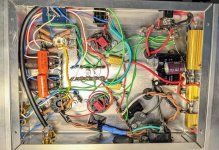
The good news: I got the amp built and working in a single chassis as I had hoped.
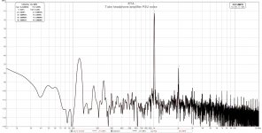
The bad: the PSU that I designed is generating audible 120Hz hum (see RTA screenshot @ ~-65dB) and generating a ton of heat. I am planning to remediate the heat problem by attaching two large heatsinks to either side of the amp, where the power resistors are mounted, but given the tools I have available I can't devise a way to do this without using thermal epoxy. So any changes I need to make to the power supply components (mounted to the side of the chassis) need to happen before I attach the heatsinks.
Any suggestions to tame the 120Hz hum are greatly appreciated. There's one suggestion here in a TubeCad article, but it requires adding a 470uF capacitor, which I don't think I have room for underneath the chassis.
I'd like to better understand how I might improve the PSU before experimenting with a virtual ground for ripple reduction. When I did PSUD sims with a larger first capacitor, I found I was exceeding the 300mA maximum current on the secondary of the transformer. That is why I chose the 33uF value for the first capacitor.
Appreciate any insights that y'all can share... always appreciate learning from everyone here!
Hi folks,
The good news: I got the amp built and working in a single chassis as I had hoped.
The bad: the PSU that I designed is generating audible 120Hz hum (see RTA screenshot @ ~-65dB) and generating a ton of heat. I am planning to remediate the heat problem by attaching two large heatsinks to either side of the amp, where the power resistors are mounted, but given the tools I have available I can't devise a way to do this without using thermal epoxy. So any changes I need to make to the power supply components (mounted to the side of the chassis) need to happen before I attach the heatsinks.
Any suggestions to tame the 120Hz hum are greatly appreciated. There's one suggestion here in a TubeCad article, but it requires adding a 470uF capacitor, which I don't think I have room for underneath the chassis.
I'd like to better understand how I might improve the PSU before experimenting with a virtual ground for ripple reduction. When I did PSUD sims with a larger first capacitor, I found I was exceeding the 300mA maximum current on the secondary of the transformer. That is why I chose the 33uF value for the first capacitor.
Appreciate any insights that y'all can share... always appreciate learning from everyone here!
Attachments
IME noise of VR tube with 0.1uF bypass will be <5mVp-p, an additional 470uF before the stabilizer will be unnecessary.
Try connecting signal common (green 0V) to mains earth at the mains power inlet (connection not shown in schematic).
IME 5687 are notorious for heater cathode leakage, try and find a 'known good' sample.
Try standing the power transformer 'off' the chassis with some insulating material.
JP
Try connecting signal common (green 0V) to mains earth at the mains power inlet (connection not shown in schematic).
IME 5687 are notorious for heater cathode leakage, try and find a 'known good' sample.
Try standing the power transformer 'off' the chassis with some insulating material.
JP
Last edited:
I think he made that connection already through the terminal under the negative of the purple cap on the right.
But If I'm seeing it correctly there seem to be 3 star grounding points? one right in the middle, then another at the powersupply where it also seems to connect to chassis, then an earth-chassis connection near the IEC plug. Could it be a matter of having some kind of ground loop?
P.S. really pretty amp, I'm actually considering to copy it
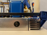
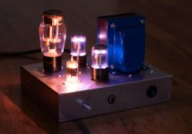
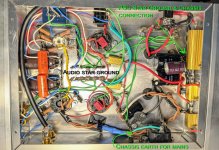
Annotated photo of the grounding scheme
Thank you, I'm flattered! Happy to share more information if you'd like. The pretty blue glow was an important design criteria 😉
Thank you all for your suggestions and resources. I'll do some experimenting after the holidays and also post some scope screenshots showing the ripple that I'm seeing at various points in the circuit.
Meanwhile, here's an annotated photo showing the grounding scheme.
I have two chassis connection points: one at the PSU ground (1st capacitor) and one at the mains earth inlet. I have an audio and a PSU star ground. The audio star ground is not connected to the chassis but it is connected to the PSU star ground via a green wire.
I now realize I was not simulating in PSUD properly when I saw the RMS current on the transformer secondary shoot up when experimenting with larger filter capacitors. I forgot to add a delay and I believe the large inrush current was throwing me off. So a larger-than-33uF first capacitor (or larger PSU capacitors all around) might do the trick.
Happy holidays, everyone!
really pretty amp, I'm actually considering to copy it
Thank you, I'm flattered! Happy to share more information if you'd like. The pretty blue glow was an important design criteria 😉
Thank you all for your suggestions and resources. I'll do some experimenting after the holidays and also post some scope screenshots showing the ripple that I'm seeing at various points in the circuit.
Meanwhile, here's an annotated photo showing the grounding scheme.
I have two chassis connection points: one at the PSU ground (1st capacitor) and one at the mains earth inlet. I have an audio and a PSU star ground. The audio star ground is not connected to the chassis but it is connected to the PSU star ground via a green wire.
I now realize I was not simulating in PSUD properly when I saw the RMS current on the transformer secondary shoot up when experimenting with larger filter capacitors. I forgot to add a delay and I believe the large inrush current was throwing me off. So a larger-than-33uF first capacitor (or larger PSU capacitors all around) might do the trick.
Happy holidays, everyone!
Attachments
The thing I'm wondering about is if that audio plug over there is making an unexpected ground connection to your chassis through the metal mantle/ring of the connector. That would maybe make a loop which potentially could introduce your hum?
And yes glowing stuff is cool! A year or two back I wanted to make something similar with a single OD3 for the smaller tube only due to current capabilities of the regulator tubes. But just slapping down two of them would of course also be a nice solution 😀
And yes glowing stuff is cool! A year or two back I wanted to make something similar with a single OD3 for the smaller tube only due to current capabilities of the regulator tubes. But just slapping down two of them would of course also be a nice solution 😀
Some ripple voltage measurements & noise @ the output
See scope measurements below -- looks like it's about quadruple that (measured at a single 0D3).
I gave this a shot but didn't notice any improvement.
This is one reason why I elevated the heaters -- I don't have any spare 5687's on hand so haven't tried a new one yet. That said, wouldn't heater cathode leakage show up on the FFT as 60Hz hum rather than 120Hz?
The transformer is stood slightly off the chassis with some rubber grommets.
I took a look and it seems the audio plug is properly insulated but thanks for the suggestion. I don't think this is a ground loop issue, it doesn't sound like one to me.
OK, so - I made some measurements today.
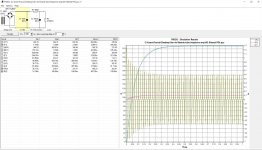
First off, the current draw of the amplifier is about 141.5mA in total. I used this number to update my PSU D simulations and to see how much ripple I should expect from the PSU.
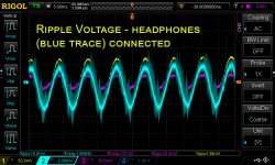
The simulation showed about 96mVPP ripple at the load; I measured 130mVPP ripple. After one of the two 0D3's I measured ~22mVPP of ripple. At the output of the amplifier I see about 10-13mVPP of ripple.
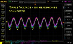
Another thing I noticed, and have illustrated below, is that with headphones plugged in the output ripple waveform gets noisier. This correlates with what I am hearing which is a faint 120Hz hum couple with some faint "shh-shh-shh" type noise.
Wanted to share these scope screenshots for everyone's enjoyment and input.
Given that I have the space in the chassis, I do think that I will put a larger first capacitor in place of the 33uF -- the largest that I can fit. I can absolutely upsize to another 100uF capacitor, might be able to go a bit bigger.
Any other thoughts and suggestions are welcome.
Thanks again for all of your input.
IME noise of VR tube with 0.1uF bypass will be <5mVp-p, an additional 470uF before the stabilizer will be unnecessary.
See scope measurements below -- looks like it's about quadruple that (measured at a single 0D3).
Try connecting signal common (green 0V) to mains earth at the mains power inlet (connection not shown in schematic).
I gave this a shot but didn't notice any improvement.
IME 5687 are notorious for heater cathode leakage, try and find a 'known good' sample.
This is one reason why I elevated the heaters -- I don't have any spare 5687's on hand so haven't tried a new one yet. That said, wouldn't heater cathode leakage show up on the FFT as 60Hz hum rather than 120Hz?
Try standing the power transformer 'off' the chassis with some insulating material.
The transformer is stood slightly off the chassis with some rubber grommets.
The thing I'm wondering about is if that audio plug over there is making an unexpected ground connection to your chassis through the metal mantle/ring of the connector. That would maybe make a loop which potentially could introduce your hum?
I took a look and it seems the audio plug is properly insulated but thanks for the suggestion. I don't think this is a ground loop issue, it doesn't sound like one to me.
OK, so - I made some measurements today.
First off, the current draw of the amplifier is about 141.5mA in total. I used this number to update my PSU D simulations and to see how much ripple I should expect from the PSU.
The simulation showed about 96mVPP ripple at the load; I measured 130mVPP ripple. After one of the two 0D3's I measured ~22mVPP of ripple. At the output of the amplifier I see about 10-13mVPP of ripple.
Another thing I noticed, and have illustrated below, is that with headphones plugged in the output ripple waveform gets noisier. This correlates with what I am hearing which is a faint 120Hz hum couple with some faint "shh-shh-shh" type noise.
Wanted to share these scope screenshots for everyone's enjoyment and input.
How about 330uF caps instead of 33uF caps.
Given that I have the space in the chassis, I do think that I will put a larger first capacitor in place of the 33uF -- the largest that I can fit. I can absolutely upsize to another 100uF capacitor, might be able to go a bit bigger.
Any other thoughts and suggestions are welcome.
Thanks again for all of your input.
Attachments
Last edited:
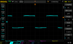
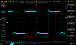
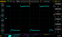
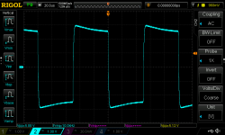
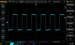
I hadn't done any squarewave testing previously so I also put some squarewaves through this amplifier with no load (the amp inverts the input phase). It's capable of quite a lot of voltage swing provided a sufficient input signal. I used one of those inexpensive transistor testers (which outputs a non-adjustable 5.12Vpp square wave).
At lower output levels the waveforms were noisy (not sure if this is just an artifact of my test setup or a sign of a problem), so I turned it up. Some scope screenshots below.
100Hz, 1Khz (low & high output), 10Khz, 25Khz, 50Khz
At lower output levels the waveforms were noisy (not sure if this is just an artifact of my test setup or a sign of a problem), so I turned it up. Some scope screenshots below.
100Hz, 1Khz (low & high output), 10Khz, 25Khz, 50Khz
Attachments

Last edited:
Did you manage to find anything that resolves your issues?
No, not yet. Going to try a larger first capacitor.
- Home
- Amplifiers
- Tubes / Valves
- Modified Van Waarde OTL HPA w/ 0D3 regulator