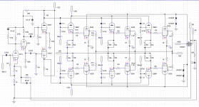
I've dabbled in tube amps off and on over the past 20 years or so - nothing over about 30 watts, and nothing left permanently assembled. Typically I build solid state, up to the kW range. About a year ago, I had this hairbrained idea to get some Tubelab kind of power. It was originally supposed to be a bass amp, but I think it will eventually become a couple of monoblocks. So far its just the one prototype, but I'm quite pleased with how it sounds. I was running 'full music' the other day, scaring the heck out of the dogs. Next will be some full power testing with a dummy load = to see if I want the next size power transformers or if I cross the magic 200 watt threshold with the ones that are in there.
It did have its share of problems, but nothing that couldn't eventually be fixed (snivets, and a total revamp of the bias board). There will be some tweaking while I'm digging up parts for a 2nd channel. I'm sure I can come up with a better layout which might let me shove the open loop pole up a little bit, and there will be some protection circuitry added besides fuses and the delay for the HT.
It did have its share of problems, but nothing that couldn't eventually be fixed (snivets, and a total revamp of the bias board). There will be some tweaking while I'm digging up parts for a 2nd channel. I'm sure I can come up with a better layout which might let me shove the open loop pole up a little bit, and there will be some protection circuitry added besides fuses and the delay for the HT.
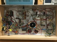
Attachments
I had a similar idea back in 1968 and built a 'burner' as we called it, power amplifier.
All home made using a power and output transformer wound and varnish vacuum impregnated, (I worked for a company that made the odd transformer), and mounted in Dexion racking.
Yes they were large.
It used two 6SN7, three 807 and four 813s. 2200volts HT in class AB2.
It could dim the lights in my workshop at full power into two 1kW electric fire elements, that I could light up in parallel, working off the 100volt line output from the output transformer, (as I said intended to use it for PA work in the factory, they let me build the transformers!)
My dad was the Chief Engineer at our local Radio Station and valves were plentiful as transmitters were being decommissioned.
Those were the days.
I had this hairbrained idea to get some Tubelab kind of power.
I have been quietly working on a big one to move the definition of "Tubelab kind of power" a bit higher.
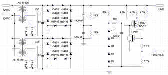
My amp uses TV sweep tubes, and aims for 400 to 600 WPC. My OPT's are rated for "400W @ 20 Hz". I have a screen regulator similar to yours and it has been the source of most of my blown parts. The big difference is that I am running my screens between 150 and 175 volts, so there is more drop in the mosfet. After blasting a few fets and a couple tubes I realized that most mosfets are designed for switching use, and not for linear regulator operation. Many do not even have a SOA spec for DC operation, and some of those that do, LIE!
There are some linear mode fets, and so far a big IXYS "L2" fet is holding up, but I added a few parts to make life easier on the tubes when a fet blows. Fets, and most silicon devices fail to a short which could put full B+ on the screen grids. I added the resistors in series with the drain, which you already have.
I have also added a pair of series connected 5 watt Zeners from the regulator output to ground. They are sized so that they never conduct in normal operation (2 X 100 volt in my case), but will eat an over voltage and fail to a short if a fet blows, possibly blowing the resistors....This happened once already, and saved a pair of tubes.
In the complete amp there will be an Arduino compatible (Teensy) board to shut things down in the event of any misbehaving circuit.
Next will be some full power testing with a dummy load
That's where I blew up mosfets. The amp could play at 200 watts with TWO output tubes (4 or 6 will be in the complete amp) for hours with music just touching clipping. A full power sine wave into clipping would run the continuous screen current up into the blown mosfet zone.
I'm sure that you know that I would use mosfets instead of 12BH7's, but if you prefer tubes, the 5687, 7044, or 7119/E182CC are better choices due to their much higher Gm which is important in a follower. These have a different pinout than the 12BH7.
I'm sure that you know that I would use mosfets instead of 12BH7's, but if you prefer tubes, the 5687, 7044, or 7119/E182CC are better choices due to their much higher Gm which is important in a follower. These have a different pinout than the 12BH7.
FWIW, the ECC99 is similar to the mentioned types and it does pin out the same as the 12BH7.
I have also added a pair of series connected 5 watt Zeners from the regulator output to ground. They are sized so that they never conduct in normal operation (2 X 100 volt in my case), but will eat an over voltage and fail to a short if a fet blows, possibly blowing the resistors....This happened once already, and saved a pair of tubes.
In the complete amp there will be an Arduino compatible (Teensy) board to shut things down in the event of any misbehaving circuit.
That's where I blew up mosfets. The amp could play at 200 watts with TWO output tubes (4 or 6 will be in the complete amp) for hours with music just touching clipping. A full power sine wave into clipping would run the continuous screen current up into the blown mosfet zone.
I'm sure that you know that I would use mosfets instead of 12BH7's, but if you prefer tubes, the 5687, 7044, or 7119/E182CC are better choices due to their much higher Gm which is important in a follower. These have a different pinout than the 12BH7.
Before any sine wave testing I need to get some 800 volt SCRs for an OVP crowbar on the g2 regulator. Goes above 380 volts (one more 47V zener), crowbar the drain resistor to ground and blow a 250mA fuse. I forgot the SCRs on my last Mouser order. I have some 400’s, but I don’t trust them with the HT at 600. Last thing I want is nuisance tripping while testing the ruggedness of the mosfet. I forget the part # at the moment, but it was selected for relatively high on resistance (1.4 ohms) and only an 8 amp Id rating. Mosfets are like Bipolars wrt second breakdown. The smaller dies tend to have a higher SOA at elevated voltages. May be a couple weeks - I’m getting an order together, which is already filling up fast. Usually it’s months between bulk orders. Not ready to buy the other 1650W yet.
I already have 4 more BH7’s, so they are going to stay. I’m getting over 100 V p-p out of the driver cleanly, and there is enough loop gain to need degeneration in the input stage (hence the high-ish feedback resistor values). One of the design constraints was to use common tubes - before I go off and do something really stupid with sweeps, But there will be other experiments before going higher power. I picked up a nice quad of 6CB5 that I can probably get 150 watts out of without spending too much on iron. That will become the bass amp. I only have a smattering of 36/26LW6’s that are all mix and match. Only one pair identical.
Goes above 380 volts (one more 47V zener), crowbar the drain resistor to ground and blow a 250mA fuse.
Good idea.
One of the design constraints was to use common tubes - before I go off and do something really stupid with sweeps
I started out playing with sweep tubes as a kid because they WERE common. I had built all sorts of stuff with TV tubes fetched from dead TV's before I ever SAW a 6550 or KT88, or could afford to buy a 6L6GC.
I picked up a nice quad of 6CB5
I have 10 or so of them, and about 20 6CD6's. Those were the biggies from the early days of color TV. I also bought a box of 100 25DN6's for $50, they are my expendable tube for experiments that might not end well.
I only have a smattering of 36/26LW6’s
I was working in a TV repair shop when I first saw a 6LW6, and it was one of the fat ones. I started collecting them cheap when EBAY first came into existence. An article was published in Glass Audio featuring the 'LW6 in 1999, and the prices have been climbing ever since.
6550's and KT88's cost me more than any sweep tube I have ever bought, so I tend to play with stuff that costs less. I only have a few 6550's or KT88's. Like your 'LW6's only 4 that are the same, and they are rather rare NOS JAN GE 6550As that I got a long tine ago for $20 each. They are seen here:
YouTube
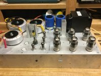
I like it! I would like to see the wiring / component side as well. And hopefully some measurements later? What class do you run? How hot do your MOSFET PSU parts get? I see you’re using quite big heatsinks. Good luck with building the 2nd channel!
Regards, Gerrit
It’s pretty low bias right now, 20mA per tube. I may go higher, but I’m not hearing any overt crossover distortion. The mosfet heat sinks are something I have in quantity - the front end regulator just gets warm to the touch and stays there. The g2 stays stone cold till the music gets pretty loud. I will probably re-do the front end power supply with an Antek 1T175. That will give me 225/450 and let me use 400V caps which I have a lot of. And cool the regulators off because of less dissipation on the one feeding the followers. When I do the 2nd one I’ll try to fit it in a 17x17 form factor, so I can make use of some really nice 3U front panels I picked up at Skycraft. Then duplicate it using parts from this one. I figured there will be some lessons learned. I’ve never built a really big solid state amp that I didn’t figure out how to re-do better. This thing sounds good enough that it’s worth pursuing building a pair of nice monoblocks. And will get me off my butt to build the 2x15” 4-way speaker design I’ve been threatening to for the last 10 years.
Attachments
I started out playing with sweep tubes as a kid because they WERE common. I had built all sorts of stuff with TV tubes fetched from dead TV's before I ever SAW a 6550 or KT88, or could afford to buy a 6L6GC.
The way I figure it is that if I’m spending $330 on an output transformer (to guarantee success) why am I going to hold out for $11 tubes, when I know I’ll be able to find 6550s or KT88s 10 or 20 years from now? For things with flameout possibilities, or may be destined for the scrap heap, sure, cheap tubes are the way to go. This was something that I intend on keeping in some form or other.
I’ve thought about trying the Antek 15T950 as an output transformer. Only $200. If I find enough LW6’s that I can parallel, I may try it. 1k a-a with 4 ohms, 500 ohm with 2 ohm load. That will drive 4 of my “DH horns” - a 32 cubic foot FLH tuned to 30 Hz and loaded with 18TBW100’s. Still got to paint those cabs this summer - the Duartex just came in a couple weeks ago. Waiting for hot and dry. The 6CB5’s are destined to drive an old 1978-vintage 18” Pyle Driver - best bass guitar speaker I’ve ever heard.
Maybe slightly into AB2, hence the 10k g1 stoppers, which should keep g1 current from going nuts. I didn’t want any rebiasing when clipping, especially with parallel tubes. Blocking in one will affect the others. Each one keeps a rock steady bias if driven from their own source. With this arrangement I get to bias each one individually, keep the gate resistance well under 50k to prevent runaway, and not load down the SN7. It’s only 2 more $17 tubes - not the lions share of the cost - and potentially better than a single follower driving it all cap coupled. Certainly keeps Rg1 under control easily - after hearing so many stories of KT88s running away with 220k bias resistors.
> AB2? Are you sure that they can cope
The Ampeg SVT needed special-selection from 6550 to spend a night in AB2.
"a couple of monoblocks" sounds like a hi-fi which shouldn't be in steady max-power condition; if it is, it won't just scare the dogs, it will call the cops. (I had sixteen 8417 at home but couldn't get near real power; cops from the *next* town would ask me to turn-down.)
A hi-fi that will occasionally get turned up to 11. Not a steady sine wave but putting out 1/8 power on average for sure (which will cook an HT receiver or most low end PA amps). It started as a bass amp idea, but ended up being too big for the intended speaker, and I kept getting asked “are you going to build stereo?”. I wanted something special to drive my next home speaker system project - preferably tubes and as big as I could get transformers for without spending $1k to get each custom wound. $1k for each channel in tubes and transformers I can stomach. I had this little 25-ish watt per channel 7591 amp in progress that I set aside to work on this. I’ve still got to figure out why it is motor boating. This one never did.
And if I wanted to bring the cops I’d get out the 30kW PA. Solid state, of course. Funny thing is I used to set it up and tune it in every so often back when I *was* gigging. Been a long time. It never did bring the cops, but playing MLS bursts more often than music, the neighbors figured that I was doing something serious with it and not just having a party in the front yard. Leave it on playing Led Zep for an hour and the results might be different. I test amps in my shop (insulated) with full music often enough. It doesn’t bring the cops, but does harass the dogs.
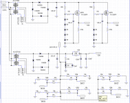
Updated power supply - and some POWER results
I got me a batch of 26LW6's for my NEXT power amp, and was thinking long and hard about the power supply. How to get a 175 V regulated screen supply, and 900 volts on the plate. Then it occurred to me - stack two power supplies. One at 200V, and the other at 700. This has real possibilities and I can actually cobble that together. Then I thought about revamping the power supply in this amplifier. I off-loaded the screen supply from the main 600V HT to the lower 400V B+. The 200VA toroid used for that is more than big enough. This allows much higher peak screen currents safely - so much that I now blew the 250mA crowbar fuse in normal operation with music at clipping - and had to bump it up to 500mA. No issue at all blowing the Mosfet. I dd have to add protection diodes to prevent the ripple filters from blowing the gate protect zeners when the supply does rapidly collapse - something I should have done earlier. It now operates completely safely with music or sine waves.
Music waveforms hit just over 70V peak with lightly compressed music (good recordings that aren't digitally clipped). That is around 300 watts music power (50V RMS equivalent). The screen voltage is obviously high enough. Unclipped sine waves hit over 58V peak, or 41V RMS, which is 210 watts. This is with a 8 ohm dummy load on the 8 ohm tap. The HT supply collapses to 538V under those conditions, so assuming the plate can be brought down to 60V the math works out perfect. That will pull 100+ mA peak screen currents in each tube and the regulator is having no problems with it. If I had left the screen supply on the main HT, the supply droop would be worse and I'd be maddeningly below 200 watts. And then always wonder about the regulator.
I have started laying out a more compact rack mount chassis which I will build two of. The $64k question is which power transformers to order for the HT - more of the 430V which I have now or bump it up to 475 in hopes of 250 watts. Only an additional $114 in total. It does hit 200 watts now, and does so safely. Should I be scared of just over 650 volt HT, with these tubes and Hammond OPT? Or call the design done and get stooooopid with the sweep tubes?
Attachments
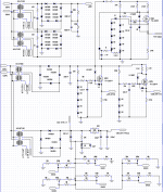
The schematic in post # 1 solves the grid return resistance problem nicely.
Individual cathode followers, extra parts, but great implementation.
Otherwise for most designers, the following applies:
1. Fixed Bias:
6550 tubes need 50K DC return resistance to ground.
If you have a 10k grid stopper, then they need 40k DC return resistance to ground.
If you have three 6550 I parallel, and each one has a 10k grid stopper, then
you need 40k/3 = 13.3k DC return resistance to ground.
The driver will probably have problems driving 13.3k.
2. Self bias:
6550 tubes need 100K DC return resistance to ground.
If you have a 10k grid stopper, then they need 90k DC return resistance to ground.
If you have three 6550 I parallel, and each one has a 10k grid stopper, then
you need 90k/3 = 30k DC return resistance to ground.
Now, the driver has to drive 30k.
KT88 Fixed bias 100k DC return.
KT88 Self bias 220k DC return.
Self Bias anybody?
Stronger Driver anybody?
"More expensive" KT88 anybody?
Which is more expensive, better tubes, or a complete re-design?
Extra Power plus Reliability at the same time do not come easily or cheaply.
Happy designing!
Last edited:
Very good - LF stability OK? Mr Zintolo may be interested in this with GU50s as it may work for his 450W bass amp.
I didn’t have a bit of problems with motor boating with this thing. Having a completely separate power supply for the front end probably helped. I’ve got another amp in progress that does have severe LF stability issues, and I put it aside to finish this. Right after a full power sine wave transient that’s abruptly cut off, I do see some low level ringing that dies in a second or two. It takes a second or two for the scope trace to settle out on zero. Amplitude level is really low, under a volt peak. If that’s all it does I’m not going to sweat it.
I’ll probably use the same general topology on the next big sweep tube amp, except that the driver stage will be hexfets. Probably need more aggressive lag compensation, as the OPTs frequency high response will be a bit less than this one (understatement of the year) and there will definitely be more parasitic capacitance.
- Status
- This old topic is closed. If you want to reopen this topic, contact a moderator using the "Report Post" button.
- Home
- Amplifiers
- Tubes / Valves
- We've got a heartbeat - 6x 6550 is alive