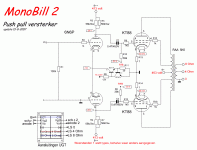
I've built an amp similar to the two stage mono Bill. My issue is that when I load the output transformer the output voltage reduces significantly. The amp just can't drive a load, about 8watts max into 8.5 ohms (dummy load).
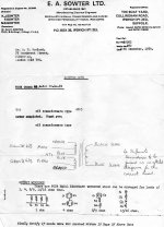
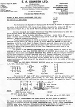
The HT is 460V, quiescent current 50mA. (GEC class AB1 ultralinear fixed bias conditions which should give up to 70W with anode to anode of 4k ohms)) Fixed bias is from Tent Labs auto bias circuit. I've also tried configuring as a basic cathode auto bias circuit, but the problem is the same (I don't think it is the Tent Labs circuit causing the issue). I've tested the driver stage when the amp is under load and it maintains its drive voltage. The output transformer is a discontinued Sowter 50W UL unit, 4K a-a, 40% taps, four output windings that can be configured for various loads. I've measured the primary winding dc resistances and they seem OK. I also applied 50Hz ac to the secondary and measured the primary (no loading) and calculated the anode to anode impedance which came out at about 3.8K ohm, a bit lower than that specified. I've tried configuring the secondaries according to manufacturers recommendations and every other which way, to try and get load tolerance, but with no success. I've also tried other, known good KT88's. I've tried varying the HT and bias with no improvement. So on the face of it, it seems a problem with the transformer, but if it is, the failure mode is odd as it appears OK on all static tests. Any ideas? Thanks. Matt.


The HT is 460V, quiescent current 50mA. (GEC class AB1 ultralinear fixed bias conditions which should give up to 70W with anode to anode of 4k ohms)) Fixed bias is from Tent Labs auto bias circuit. I've also tried configuring as a basic cathode auto bias circuit, but the problem is the same (I don't think it is the Tent Labs circuit causing the issue). I've tested the driver stage when the amp is under load and it maintains its drive voltage. The output transformer is a discontinued Sowter 50W UL unit, 4K a-a, 40% taps, four output windings that can be configured for various loads. I've measured the primary winding dc resistances and they seem OK. I also applied 50Hz ac to the secondary and measured the primary (no loading) and calculated the anode to anode impedance which came out at about 3.8K ohm, a bit lower than that specified. I've tried configuring the secondaries according to manufacturers recommendations and every other which way, to try and get load tolerance, but with no success. I've also tried other, known good KT88's. I've tried varying the HT and bias with no improvement. So on the face of it, it seems a problem with the transformer, but if it is, the failure mode is odd as it appears OK on all static tests. Any ideas? Thanks. Matt.


Hi dimitri. That results in much more sensitivity to input voltage, but the sine wave is very rounded and the output collapses under load as before. Cheers. M
Has this amplifier performed OK or is this a new build?
Do you measure the 50 mV on the cathodes?
Does your current go above 50 mA when playing louder?
Is your G2 screenvoltage stable under load?
Regards, Gerrit
Do you measure the 50 mV on the cathodes?
Does your current go above 50 mA when playing louder?
Is your G2 screenvoltage stable under load?
Regards, Gerrit
Hi gerritube. The grid stays at about -51 volts with respect to the cathode (about 50ma, I'm using the Tent Labs auto adjust bias) regardless of signal level. The screen voltage and anode voltage drop by about 3 volts under load, as the output voltage on the secondary drops by over half in level.
Has this amplifier performed OK or is this a new build?
If you drive the amplifier with music or sine wave for full power, does you current to above 50 mA?
Regards, Gerrit
If you drive the amplifier with music or sine wave for full power, does you current to above 50 mA?
Regards, Gerrit
gerritube. This is a new build. The quiescent current as measured on my multimeter (dc setting) stays constant regardless of signal level.
pwgtang. The output is ok until under load, also the driver stage remains constant as the output stage sags under load, so it's not the driver stage.
pwgtang. The output is ok until under load, also the driver stage remains constant as the output stage sags under load, so it's not the driver stage.
Hi Matt,
I’m wondering if your driver stage gives your finals enough drive. You could measure the RMS or PtoP voltage there too. It’s a bit weird you’re not possible to drive the final tubes to draw some extra current with full drive.
Regards, Gerrit
I’m wondering if your driver stage gives your finals enough drive. You could measure the RMS or PtoP voltage there too. It’s a bit weird you’re not possible to drive the final tubes to draw some extra current with full drive.
Regards, Gerrit
The amp not enough gain, may need one more driver stage.
This is the open loop design, capable to produce 40W output with 2% THD, 2.7-2.8Vrms input
Wie is MonoBill? Het is een KT88 Push Pull versterker, gemaakt voor de man of vrouw die graag wat meer uitgangsvermogen wil... - Audio-Creative
Having trouble uploading scope screenshots. However the control grid signal stays constant with output loaded or unloaded, so I don't see a problem with the drive. The output voltage on the secondary of the o/p transformer drops from 20V rms to about 7volts rms with 8.5 ohm load (secondaries configured for 8 ohm load), the wave form stays fairly un-distorted (all at 1kHz).
So it drops from 20v rms unloaded to 7v rms loaded? This is normal and reflects the highish output impedance of an ultralinear output stage with no negative feedback. By the way you shouldn't test unloaded with large voltage swings, you can potentially damage the output transformer (although pentode connection is usually worse for this).
tikiroo With this transformer and the GEC AB1 fixed bias, ultralinear settings I've used, the amp is supposed to give 50 watts. 7volts across 8.5 ohms is about 6 watts.
With a clean 36V rms on the grid, the output with 8.5 ohm load is a badly distorted 19.2 V rms. According to the GEC data it should be about 2% distortion, it looks a lot worse than that to me. I don't have a distortion meter. I can't understand how the Bill design without feedback can be considered good if this is the result.....
- Home
- Amplifiers
- Tubes / Valves
- New year trouble shooting a KT88 output stage