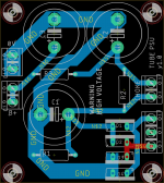
This is a simple PCB for CRCRC (or CLCRC) PSU for a small tube amp.
The size is intentional -- the mounting holes fit right under (using the same mounting screws) of an Edcor PT I plan on using.
Need some help with the grounding -- the intent here is to take the 0V point of the PCB and tie it to a star ground on the chassis, where the amp PCB and speaker outs will be tied to as well.
In this case, is it better to locate the 0V north of the B+ near the output cap, or does it not matter because of the pour?
If I remember correctly, the preferred place to tie to the chassis is the (-) of the first filter cap. In that case, is it actually better to use a star ground on the PCB instead of a pour?
Thanks!!
Attachments

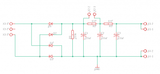
OK I think this one is a bit better. The resistors weren't routed properly on the first one (both resistors had a direct connection)
There is a lot of empty space on the board, but as mentioned the positions of the mounting holes are intentional.
Any suggestions? Snubbers for the rectifier or heater elevation?
There is a lot of empty space on the board, but as mentioned the positions of the mounting holes are intentional.
Any suggestions? Snubbers for the rectifier or heater elevation?