Hi
Not sure where to post this question.
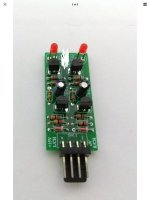
I purchased a 2 channel circuit board online listed as a clipping indicator for preamps and power amps.
The LEDs turn on when only 1.2Vdc is applied to the signal pins (not sure if this is a legitimate test).
The board’s supply voltage is 15V.
I have tried to understand how the circuit function and came to the conclusion that there is an LED driver circuit with one transistor that reacts to the voltage difference between the rail voltage and the signal voltage, controlled by another transistor.
I am not sure how this board is to be used.
Is its power supply independent of the amplifiers or is it the same?
Is it only suitable for preamp level signals or amplifier level signals?
How does it work?
The seller is giving nothing away although I was kindly provided with the schematic. I deidentified the photos to avoid any issues.
Not sure where to post this question.
I purchased a 2 channel circuit board online listed as a clipping indicator for preamps and power amps.
The LEDs turn on when only 1.2Vdc is applied to the signal pins (not sure if this is a legitimate test).
The board’s supply voltage is 15V.
I have tried to understand how the circuit function and came to the conclusion that there is an LED driver circuit with one transistor that reacts to the voltage difference between the rail voltage and the signal voltage, controlled by another transistor.
I am not sure how this board is to be used.
Is its power supply independent of the amplifiers or is it the same?
Is it only suitable for preamp level signals or amplifier level signals?
How does it work?
The seller is giving nothing away although I was kindly provided with the schematic. I deidentified the photos to avoid any issues.
Attachments
It would be connected in parallel to your speakers (power amplifier output).
It works by detecting DC on the amplifier output, as would occur at clipping, or during a fault condition.
It works by detecting DC on the amplifier output, as would occur at clipping, or during a fault condition.
It works by detecting DC on the amplifier output, as would occur at clipping, or during a fault condition.
Only clipping to positive rail or when DC is positive, but this circuit does nothing on negative going failures.
Also R1 and R2 must be properly calculated for each power output amplifier, a 1W amp will have a swing in the output much less than a 1000W, and the schematic below have no account on this fact. Please, discard it.
Last edited:
Good point but clipping will usually hit both rails. OP already has a speaker protect circuit.Only clipping to positive rail or when DC is positive, but this circuit does nothing on negative going failures. Discard it.
Not necessarily. If one of the output transistors, for example, degrades having leak between collector and base or emitter, then middle point will go in such a direction, and clipping will occur in such a direction only. If the amp is DC coupled to load, it will overheat or blow the speaker.
Speaker protection circuit should kick in if this is the case. That's not the purpose of the clip detection.Not necessarily. If one of the output transistors, for example, degrades having leak between collector and base or emitter, then middle point will go in such a direction, and clipping will occur in such a direction only. If the amp is DC coupled to load, it will overheat or blow the speaker.
This indicator has NO CLUE on rail voltages, distance to them, DC or clipping so not an indicator for any of those.
It is just fed 15V supply (main rail voltages can be *anything*), Q1 turns on when peak voltage at the input is : 0.7V+ (0.7 * 1.5)V so some 1.7V peak so some 1.2V RMS or close to nominal +4dB, where "many Pro amps clip".
That it actually does or not is sheer chance.
File it in the "blinking lights" cabinet.
You're quite right. I thought the capacitors were doing something useful to detect DC but ... not really. This really is pretty useless then.This indicator has NO CLUE on rail voltages, distance to them, DC or clipping so not an indicator for any of those.
It is just fed 15V supply (main rail voltages can be *anything*), Q1 turns on when peak voltage at the input is : 0.7V+ (0.7 * 1.5)V so some 1.7V peak so some 1.2V RMS or close to nominal +4dB, where "many Pro amps clip".
That it actually does or not is sheer chance.
File it in the "blinking lights" cabinet.

1. This circuit detects positive peaks above about 1.6V.
2. a better circuit has an adjustable threshold to match your amplifier output.
3. A better yet circuit detects both positive and negative peaks.
4. A better yet, yet circuit compares the output to the power supply and indicates the output peaks near that voltage.
5. A better yet, yet ,yet circuit measures the feedback in your amplifier or compares the output to the input to detect that the output was unable to follow the input.
6. A better yet, yet, yet, yet circuit monitors the output protection to indicate current limit protection as well as voltage limits.
1. This circuit detects positive peaks above about 1.6V.
2. a better circuit has an adjustable threshold to match your amplifier output.
3. A better yet circuit detects both positive and negative peaks.
4. A better yet, yet circuit compares the output to the power supply and indicates the output peaks near that voltage.
5. A better yet, yet ,yet circuit measures the feedback in your amplifier or compares the output to the input to detect that the output was unable to follow the input.
6. A better yet, yet, yet, yet circuit monitors the output protection to indicate current limit protection as well as voltage limits.
A circuit that met the criteria of 1 through 4 would be very useful.
This circuit is silly and useless in the hands of someone that knows how it works. And anyone that knows how it would would build a better circuit of their own.
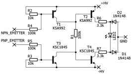
Q2 sits normally hard-ON, shorting-out the LED so it stays dark.
An input which turns Q1 on will turn Q2 off, lighting the LED.
The input needed is almost independent of supply voltage and is between 1.2V and 1.8V. Rule-o-thumb says 2.5*Vbe but Vbe will vary with device (and temperature). More to the point: it may turn-on with 1.2V steady, but brief musical transients may have to exceed 1.7V to discharge C1 enough to allow Q2 to turn-off.
These are peak Positive voltages.
For power amps with typical 1.0 to 1.2 Vrms rated sensitivities, this will approximately indicate "clipping". It won't be an exact fit, but short clipping is fairly benign and extended clipping is bad-- this gives you a clue.
While I have seen many single-sided transients they were only a half cycle and thus "brief", hardly worth knowing. I have also worked with Male Speech which can have consistent asymmetry but we rarely want to hear this LOUD and anyway a bit of clipping does not hurt speech intelligibility. On musical climaxes, if either side clips, both sides are near clipping. This light will tell you to turn it down.
There are "some" power amps with much lower sensitivity numbers, like 0.6V. If you light this LED with these amps they are already in gross clipping.
The input impedance changes from near infinity below 0.4V to a few dozen Kohm above that. This will not bother most solidstate preamps but will add distortion on a few tube preamps.
Personally I compare output to input , use that to trigger a LED, which either shows distortion (duh) or , more useful, triggers a limiter to avoid hard clipping .
Works like a charm.
The original circuit is not as silly as it looks, in fact it´s a quite useful "pulse stretcher".
If input peaks were detected then straight driving a LED, human eye slowness will not register short clipped peaks, but here any narrow peak will discharge the capacitor REAL fast, turning LED ON, and that capacitor will recharge (turning LED OFF) after some quite longer time constant.
There´s more than meets the eye (in this case, literally 😉)
I would like to test this circuit. Can anyone tell whether it is supposed to run off an independent supply or from the amplifier’s power supply?
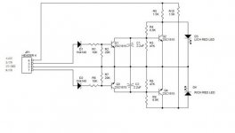
It seems to be designed to run from a power amplifier's rails (upto 50V or so), hence the large series resistors for the LED and the 120V transistors. When the inputs reach within a few volts of either rail T1 or T3 start to turn off, allowing R1 to turn on T2 or T4. At 50V rails the LED gets about 15mA.
Yes, it turns LED ON when speaker out rail gets within 6V of any power rail.
Since typical power transistor + driver saturation voltage is about 4V , it´s quite accurate.
Best is that it tracks rail voltage no matter what.
Very clever.
Since typical power transistor + driver saturation voltage is about 4V , it´s quite accurate.
Best is that it tracks rail voltage no matter what.
Very clever.
Yes, it turns LED ON when speaker out rail gets within 6V of any power rail.
Since typical power transistor + driver saturation voltage is about 4V , it´s quite accurate.
Best is that it tracks rail voltage no matter what.
Very clever.
Absolutely true. Crest engineers are clever guys 🙂 Sensitivity can change with the value of R4, and R5. Maximum theoretical supply voltage is +/-120V, but the 3.3k resistors must be modify, to set approx 20mA current for the LED. The current version was used to +/65V.
Sajti
- Home
- Amplifiers
- Solid State
- Clipping circuit