However: no peak-stretching.
No with this version, but You can use optocoupler instead of the LED to drive limiter circuit. Anyway high efficient LED will be visible. without streching.
Sajti
Hi
Not sure where to post this question.
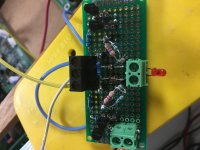
I purchased a 2 channel circuit board online listed as a clipping indicator for preamps and power amps.
The LEDs turn on when only 1.2Vdc is applied to the signal pins (not sure if this is a legitimate test).
The board’s supply voltage is 15V.
I have tried to understand how the circuit function and came to the conclusion that there is an LED driver circuit with one transistor that reacts to the voltage difference between the rail voltage and the signal voltage, controlled by another transistor.
I am not sure how this board is to be used.
Is its power supply independent of the amplifiers or is it the same?
Is it only suitable for preamp level signals or amplifier level signals?
How does it work?
The seller is giving nothing away although I was kindly provided with the schematic. I deidentified the photos to avoid any issues.
I set this circuit up on the bench with a 15vdc supply, independent of the preamp supply.
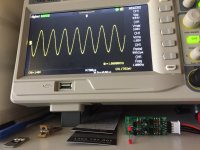
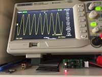
I supplied the preamp with a 1khz sine wave and used a 150K resistive load. I scoped across the load and also attached the circuit across the preamp output.
Preamp clipping starts at about 3.1Vrms on the DSO. The clipping LEDs behave a bit strangely depending upon how quickly the signal amplitude is raised up and down around clipping presumably as a response to the 10uf capacitor charging and discharging (NB the circuit diagram shows 2.2uf caps but I received 10uf). It initially turns on at about 2.4Vrms but they will light up if the signal is kept at 1.8-1.9Vrms for 10-15s. Even at this lower voltage the LEDs are reasonably indicative of the volume setting on the preamp (less than half an hour turn on the clock, if you know what I mean).
When I play actual music through the circuit I would say that it clearly approximates when the clipping voltage is approached (2.6Vrms). The capacitor’s charge/discharge effect is not present with a dynamic signal as it was with the fixed sine wave. So for preamp monitoring this does appear to be a reasonable indicator circuit. Maybe it is not just a dumb blinkie at all.
Looks like it might operated equally well on a 9v battery.
Attachments

Good day and happy new year
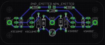
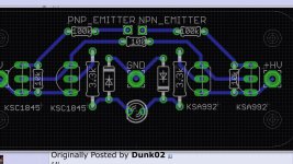
I built the circuit presented by staji in post # 15. It works but I have two questions. I’m sorry my abilities are as a mechanic and I can’t answer them myself.
1) there is a discrepancy between the schematic and posted pcb. The 100k R1 in the schematic is shown as 100 in the pcb. I used 100k but am unsure what the correct value should be.
2) the led lights at almost exactly the same time as I see clipping on my scope. It is mentioned that by adjusting the value of r4 and r5 the sensitivity could be fine tuned. I’m unsure of which way to go to have the led trigger a bit sooner.
I’m testing on an amp with +\-65 volt rails but will be implementing on amps with +\-86 volt rails
Thanks for the help
Evan
Attachments

2) the led lights at almost exactly the same time as I see clipping on my scope. It is mentioned that by adjusting the value of r4 and r5 the sensitivity could be fine tuned. I’m unsure of which way to go to have the led trigger a bit sooner.
Thanks for the help
Evan
Good idea, sensitivity could be tuned with R2 and R3 values too.