Greetings from Dubai

Hi there guys,

Having been a teeny bopper and spent several years blasting sound from cars and to some extent having matured enough to start with my listening system.

As it starts now I have re-purposed my car audio system to be my “listening” system where I aim for quality.

The system is basic and compromises of a pair of 6.5” splits and 2 x 12” sub which was my December challenge powered by a 4 channel Amp.

Whilst I was working I do some deep thinking and as such have decided to go full DIY on a Stereo Amp and speaker cabinets.

For speakers I am swaying towards GR Research and have been looking at the Modulus 686.

I welcome all your valuable insights and advice.

I am completely new to this so please be gentle 😀

Cheers Al

Bose Acoustimass 10 IV bass problem

I would like to ask about who had encountered a problem in Bose acoustimass 10 series IV like the active subwoofer speaker unit, the bass sounds at first but after a few songs, the bass went off, the bass goes back again after I replugged it to the mains. I thought that the problem was from the Sony Receiver but it wasnt because I connected another amp and the bass was there. I replaced the heat pads of the transistors inside with mica and thermal grease (cause I thought it was an overheating issue) but the problem still persists. I've checked the 2 embedded subwoofers and their fine. The components of the main amplifier are almost smd, please can someone give me some advice cause Im confused 🙁

DSP filter: how does it work in commercial speakers like Martin Logans?

Hi,

currently I'm building a hybrid electrostatic loudspeaker: a combination of a magnetic woofer and an electrostatic mid / high panel. I use an external MiniDSP 2x4 HD and two seperate power amplifiers and one pre amplifier to power this loudspeaker.

If I'm correct, the hybrid Martin Logans (for instance) use an integrated power amplifier for the subwoofer together with an inegrated DSP to filter frequencies to esl panel and subwoofer. But when looking at the pictures, I only see two regular loudspeaker input terminals, so I would guess you can only connect them to the output of a integrated / power amplifier. (not line-level)

I was wondering how DSP takes place? Is the power / amplified signal used for the subwoofer and if so, does it pass a DSP? I hope my question makes sense as I'm interested in a similar solution for my own DIY hybrid loudspeaker, just to make it more compact.

Is there a program available to help with design of a FAST/WAW?

This is the first time I've attempted to build a FAST and I am wondering if there are any hard and fast rules? For instance how does one determine the placement of the drivers on the baffle, is it similar to mounting a mid-bass and tweeter? The FAST builds I have looked at seem to be crossed over in the 200 to 500hz region so any help with the crossover point and other parameters would be much appreciated. I will be using a MiniDSP 2x4HD for crossover and tuning and I have a UMIK1 for measurement.

This project is an evolution of the Nautilus tapered transmission line for full range driver idea I had. The drivers are a Wavecor FR090WA02 3-1/2" Aluminum Cone Full-Range 8 Ohm: Wavecor FR090WA02 3-1/2" Aluminum Cone Full-Range 8 Ohm and a Scanspeak Discovery 18W/4434G-00, 7" Midwoofer, 4 ohm: Scanspeak Discovery 18W/4434G-00, 7" Midwoofer, 4 ohm

Thanks for any replies.

Live with PURIFI Co-Founder Lars Risbo!

Just a heads up for those who may be interested...

Next Thursday (Jan 21, 2021 @ 11am Central Time) I will be going live with PURIFI Audio co-founder Lars Risbo via YouTube (see link below)! This is gonna be awesome!


Join us for a Q&A regarding the tech behind PURIFI's unique transducers plus a quick view of their in-house analyser they built as part of the project. Given that Lars is +7 hours ahead of me we will be doing this at 11am Central Time.


I'll have some questions of my own but if you are able to join and ask some, please do. Let's show Lars support for being so willing to take time out of his busy schedule to help educate us all on transducer engineering and to share some cool insider bits of info.


See ya'll then!


Live with PURIFI Co-Founder Lars Risbo! - YouTube

rectifier board setup and capacitors values

Hi there,
I am completing parts for MX50 SE amp. PSU is the place I have most questions.
Transformer I have ordered will be 2x25V 250VA . Amp will drive 8ohms speakers. This power will be enought, even 25VAC after rectification will excees power and my listening volume needs.


Now my concerns regarding rectification. I don't want to wait for shipment of some kits from China but I see mostly two options in peoples projects.

8x2200uF such here
or 4x10000uF like here.

I am thinking about making two separate rectification boards , one for each secondary winding and MX50 module/channel. Now - will board with full bridge rectifier and 2x10000uF will be OK? Or better do it on 4x2200uF ?

I can purchase board like attached and I could arm this with two 20k uF caps.
view
I really wanted to understand how to calculate it, even simulate in PSUD2 software but sooner I will go crazy as simply I am not fluent in this matter yet.

It seems those values are simply that I can "go for" but I'd rather make sure and I like to understand.
Thank you
Jacek


Thank you

Restoring a Bogen CHB100 - advice appreciate for a novice

Hello there,


You guys helped me tremendously when I put together a F2B preamp clone so I thought I'd shoot some more questions here, I'm still fairly new to tube amps but I learned a lot with the preamp build.


I've been using this Bogen CHB100 as a bass amp for about a year now. The only things I've done to it was replace the old-style microphone jack to a 1/4 inch jack for ease of use, and swap the 12ax7 tube for a newer one I had laying around. I really dig the sound I've been getting from this... it's clean but gives a nice distortion if I set the gain at 7-8 and keep the volume low. I understand people do more modding to these for guitar amps to get a more colored tone, but the clean-ness works well for my bass application.

However, recently I've been getting more and more distortion even with gain set low and regardless of volume position.

It seems the amp has the original 7868 tubes in it, as well as the original filter caps, and from what I've read one of these two could be the problem. I've wanted to replace both for a while now just to keep this amp healthy and avoid any spontaneous failures, so I feel like now is the time to do it, and if it solves my distortion problem, that's grand, and if not I'll address it afterwards.

The tube swap will be easy, I'm getting 7868 to 7591 pin adapters and going to buy a matched quad of 7591s to use, and all that makes sense to me. Replacing the filter caps is what I'd like advice on. Attached are pictures of the guts, and a schematic of the CHB100. On the schematic I have circled the four caps that correspond to the large brown caps in the pictures. Are these the only ones that I should be replacing or should the blue caps in the photos also be replaced?


Will these caps from Stewmac be the appropriate replacement? Sprague Atom Electrolytic Caps | stewmac.com (See 100uf, 350v choice for brown caps)

I have a heavy-duty resistor/alligator clamp setup that I made for draining the caps and have done that before, so know that I am being safe about this. I would just like opinions from those more knowledgeable about what caps need to be replaced and what exactly I should be looking for as replacements.

Any info appreciated, thanks so much.

Attachments

  • 20210111_123503.jpg
    20210111_123503.jpg
    537 KB · Views: 170
  • 20210111_123517.jpg
    20210111_123517.jpg
    484.8 KB · Views: 144
  • 20210111_123548.jpg
    20210111_123548.jpg
    438.6 KB · Views: 157
  • bogen-chb100b-6-edited.jpg
    bogen-chb100b-6-edited.jpg
    838.2 KB · Views: 187

VBE Multiplier current compensation resistor

Hello all,


Wondering if anyone has done tests to optimize the value of current compensation resistor (R39 on the attached schematic) to minimize the shift in amplifier bias setting with changes in the +B supply rail voltage. If so, what results were obtained.


I just ran a real world test on various values of resistor ( 0 to 91ohms) and found the optimal value to be 36ohms, which is much higher than the conventionally suggested value of about 13ohms for the 10mA VAS current being used. Interestingly this agrees with the optimal value which my LTSpice simulations predicted while designing the amplifier. At that time I suspected my SPICE simulation was erroneous since it did not agree with what I read in certain books on amplifiers.

Attachments

  • 2021-01-06 (1).png
    2021-01-06 (1).png
    264.2 KB · Views: 761
  • 2021-01-06.png
    2021-01-06.png
    171.7 KB · Views: 750

Tube Upgrade Recommendation for Elekit 8600S

Hi all,


I recently completed the kit build and am running the Cossor Black Plates per Victor's suggestion (as a starter set since I was not in a position to afford the Elrogs or Psvane ACME/WE's). I have about 40 hours on them now and think I like their sound, but because I am new to tubes (my first tube amp) I have nothing to compare them to. I have done a ton of reading about other offerings and am trying to decide what direction to go in as an alternate/upgrade to the Cossor. I'm posting here as I am specifically looking to see what others have listened to on the 8600S (or similar builds). My list includes: EML, Psvane ACME or WE, Linlai comparable, Audio Note, Takatsuki and EAT. EML seems to have the most reliability and best warranty of all tubes listed, so is high on my list. I've heard great things about the Takatsuki's but I do worry about reliability for such a steep cost on the Tak's with a warranty that isn't reassuring. I am not interested in the Elrogs as they won't fit under the cage which is essential for me as I have a dog and kids that could pose a threat when I'm not in the room with a yard stick in my hand. 🙂 Princess Sophia? Perhaps.

Any insights would be greatly appreciated, especially if you have experience with the same amp, since I understand tubes can vary in sound signature depending on what amp is driving them.


Thanks!

MtX Thunder 920001 Thermal HELP!!

I just finished totally rebuilding this MTX Amplifier. The amplifier ran fine outside of the case and heatsink for testing. As soon as i put the board into casing. Also redid the thermal pads to ceramic?
I could really use some help with this protection curcuit. Nothing is getting hot.

Attachments

  • 16105884974705466441233191425560.jpg
    16105884974705466441233191425560.jpg
    997.5 KB · Views: 68
  • 16105885317765408391154095618091.jpg
    16105885317765408391154095618091.jpg
    1 MB · Views: 69

WMTMW idea.

I'm dreaming about a project where BSC could be avoided and 1st order crossovers could be used, to achieve high sensitivity.

1. Two side to side woofers in a bipole configuration, close as possible to the tweeter
Enclosure: ML-TL

-question A, how high can I cut these? How about 200 to 300Hz for 7" midbass units?

2. Two 5" mid-range units in MTM configuration. Being the same impedance as the woofer's and same sensitivity. Enclosures: sealed or dampened quarter wave

-question B. Baffle width gets tricky, isn't it? I need to make it wide enough to avoid baffle step roll off soonest than woofer roll off.

3. Lowest roll-off of the tweeter as possible. I'm aware of the right lobing of MTMs.


What kind of other problems and difficulties should I expect in such project?

USA sources for Transformers

I've done some basic searching and it seems to me that the sources for transformers suitable for tube amp projects (for Hifi) are in short supply in the US. And it seems to me that NONE of the "higher end" Japanese brands are available here at all (ie., Tamura, Hashimoto, Iso (Tango). Who do we have that build products that compete in that league? Or is Hammond right up there? Who else.


Can you folks list the manufacturers that are readily available in the USA for purchase?


Justin

P3A based question ....

Now i need some advise ....

Current set up in my house is a P3A dual mono at 48+48 rails with 1302-3281 outputs @50 ma bias ....

Ok rails are a bit on the risky side Load also is low about 5ohms so i kept the bias low
Listening demands are very low i think that the average power needed should be no more than 20 W
Obviously i know i am out of SOA but since i operate the system and no one else will abuse it i might get away with it ....

Now my actual problem is bias meaning that amplifier plays superb when warm ,,,So given the conditions above if i crank up the bias @100 ma i think i am pushing my transistors way too much ...Often i power up my amp in the morning to go home in the night to listen ....or i keep it always on the weekends

remember i live in Greece so in my home as we speak temp is 18-22 degrees but in the summer time it could easily go 35 .....

One solution will be to go for 1216 combo .... 15 MHZ more faster( 40 instead of 25 ), 17A instead of 15, and generally better SOA , also LAPT technology ....

any ideas ? Lowering rails or adding more transistors is out of the picture ...

too small box, active assists

- anyone having experience with the subject or who just wants to leave his critical comment concerning the sound quality within the limiting factors given is pretty much welcome to discuss the pros and cons of the active assists -

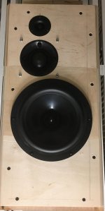
I am planning a too small box for a 2-way topology speaker.* My very personal domestic acceptance factor** allows for about 45 liters, gross dimensions being centimeters 60 × 34 × 30 (H×W×D). This is too small for a pro driver which is supposed to do the work from ~ 1.2/1 kHz downwards. There is two solutions to my knowledge, given the box volume is set and the topology is not changed:
- 1) A Linkwitz-Transform shelf-filter EQ of a sealed enclosure. Can only be achieved true active.
- 2) Parametrical equalizing of a vented enclosure, Q=2, slightly above very low tuning frequency. Can be achieved active or passive + EQ. Don Keele wrote about it 1975, AES paper attached. Lowcut is necessary to prevent high cone excursion below tuning frequency. This leads to very high group delay in low frequencies.

With the Hypex Amps both can be done. Before I chose to go active because of the time alignement of the drivers, I found the FaitalPro 12PR320 driver to be a very good choice for the woofer. Vented was still the idea then. Taking this driver as a start for comparison of both solutions, the question is what happens to sound reproduction. Here are two examples which take the Xmax of the driver as the limiting factor and power consumption on the other hand:***

Example for Version 1), a LT sealed:
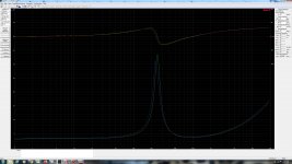
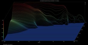
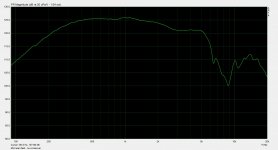
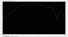
If the LT is set to F3 @35 Hz, cone excursion peaks at 25 Hz and 7.3 mm within Xmax with a system input power (Win ISD) of 8 watts which translates into ~ 85 watts drawn for bass reproduction on each channel. Group delay is ~ 20 ms @ 20 Hz. 95 dB will be reached at a listening position 2.5 meters from the speakers (couch).

Example for Version 2), Boost-Cut vented PEQ:
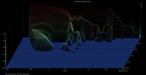
With a box tuning of 30 Hz, a Q=2, +10 dB @ 35 Hz, 21 watts would be maximum system input power before Xmax is reached, but the amplifier load is already exceeding the specifications of FA123 bridged-mode (125 watts into 8 ohm), so it has to be limited to 16 watts system input power to avoid clipping at 125 watts amplifier load for bass reproduction. Xmax reaches 6.1 mm below and 4.3 mm above tuning frequency. SPL at listening position is naturally higher than Version 1 at 98 dB. But Group delay exceeds 30 ms below 20 Hz, up to 35 ms!

This means: version 1 (LT-sealed) is fundamentally limited by Xmax, while version 2 (vented PEQed) with a +10 dB @35 Hz is limited by power alone. But it needs considerable amounts of power to be extended to reach Xmax (165VA @ 35 Hz or 16 watts system input power, compared to half the peak value of 86VA with LT). Then, it could play up to 99 dB at a 2.5 meter listening position, whilst Group delay reaches 35 ms at the threshold of low frequency audibility at 16 Herz. This can easily be audible.
Also, for very high listening levels bass extension can be sacrificed (which can be done with switchable presets within FA123, either as a decrease of EQ boost or as a higher-F3-Linkwitz transform).

The trade-offs of both designs:
- Lower Group Delay (V1) versus less Cone Excursion (V2)
- Lesser Power consumption (V1) versus higher SPL (V2)

Is there measurements available on the impact of LT/Low-Boost EQ on distortion? I would like to see the rate to which it is rising with increase of Xmax and power. I suppose cone excursion will affect higher frequencies as distortion, what sort of distortion? Intermodular? The vented version can be louder but it has a much higher group delay which may be audible, although it is reaching critical levels very low and exceeds them at the limits of low-frequency audibility for Humans. Do you see other trade-offs which I did not mention? Which direction is the compromise for better sound in your opinion?
________
* CD + horn/waveguide and 12-inch pro woofer, each a Hypex FusionAmp 123 plate amp. So far, so conservative.
** Not related to my partner or any person I would share the appartment with. And not at all to the their gender, as this is not the reason why I would not want to build a ridiculously large monument into my own living room.
*** The driver has Xmax 7.5 mm and high power handling. The Fusion FA123 in bridged mode has a good amount of power too (~125 watts into 8 ohm). The driver (EBP 107) can therefore work in a sealed enclosure, Linkwitz transformed, or in a vented enclosure EQ-boosted.

LED power indicator from heater circuit

I split my amplifier into two chassis for a myriad of reasons but now I don't have access to the voltage I need to run my led power indicator. I was thinking running it off of an AC heater circuit I have would be perfect given the ac signal being close to 3 volts due to the diode effect of the led.
I am a little concerned with introducing noise since the led will be switching on and off at 60hz. ( or maybe 120hz?)
So is there an easy way to isolate it so it can't put any noise into the heater line or am I worrying about nothing?

Jeff

Total beginner - Help picking a design to replace Linn Majik 109s

I'm new to the world of DIY, but have been into Hifi for more than 20 years, I currently have 2 separate systems, my main Linn Akubarik stereo system, and a secondary Linn Majik surround sound set up used only for TV duties.

My general approach is to build a DIY replacement for my existing setup which improves on the sound quality - main aim is to replace my stereo setup.

To get my DIY career started and learn the ropes I thought a "simple" bookshelf build from an existing design would be a sensible idea.

being new to the DIY world, and not knowing anything about pros/cons of drivers I'm struggling to pick a design which is going to provide an improvement over the Majik 109s. I've looked at a number of designs which seem sensible but I've got no idea how to pick the right 1 for me.

would be good to understand how to go about picking the right design.

thanks in advance!

FS: AudioTechnology 18H52-17-06-SDKA

Second pair of drivers to sell. 2021 will be the year I will STOP DIY.

A pair of AudioTechnology 18H52-17-06-SDKA.
NEW.
Box opened jut to take pictures.

They are a special order from AT and priced to 350€ each, the SDKA (Kapton-Aluminium voice coil version)

I will sell the pair for 400 euro + Shipping + PP fees.

they are the perfect pair fro the Scan Speak Revelator D2905/990000 tweeters I have for sale in another thread, and both are the drivers for Jeff bagby's Spirit Winds

An externally hosted image should be here but it was not working when we last tested it.

An externally hosted image should be here but it was not working when we last tested it.

An externally hosted image should be here but it was not working when we last tested it.

An externally hosted image should be here but it was not working when we last tested it.

An externally hosted image should be here but it was not working when we last tested it.

Are my speakers any good?

I got my speakers for free from someone who was moving house and had to get rid of them quickly.

mordaunt-short-ms55ti.jpg


They're Mordaunt Short MS55ti.

They have x2 8-inch drive units (each side) and a titanium tweeter. Non-ported cabinet.

I'm fairly happy with them but as for any hi-fi person I'm always looking at ways of improving things and just wondered how good the MS55ti is and how much I would have to spend to get something better?

Re-building old sub with Visaton tiw 200 XS

Hi All


I need advice to get my old sub back in game.


Some 15 years ago I built HT DIY subwoofer project following some advises from community.
Driver used is visaton tiw 200 XS
TIW 200 XS - 8 Ohm | Visaton


Box is BR app. 54liter(brutto) box made from 25mm MDF with double internal bracing.


At the beginning I was happy with sub for HT but my neighbors not so.
As I have grown older I found out that I like this sub more when I close bass reflex port with some foam.


Few years ago plate amp on this sub died and I stooped using it.
Now that I got new nice L/R/C speakers, KEF R3, R2c I would like to put it back in game.


This time I would like to have closed enclosure as I think it will be more controlled and I need only just a little help for my front speakers.


Can you advice if I need to make enclosure smaller or just fill it with some dampening material as I reed on drivers web page for closed enclosure advice to be 30 l/closed--46 Hz/0,68enclosure but mine is 50l at the moment.
I plan to simply close BR tube with foam.


Sorry for my English


Thanks

Attachments

  • IMG_20210112_191941_resized_20210112_072024925.jpg
    IMG_20210112_191941_resized_20210112_072024925.jpg
    351.9 KB · Views: 325

FS: ACA monoblocks 1.6 silver face

Sold, These are in very good physical and operational condition. These sound great driving my AN super 12's. Very low hours.
Mismatched power supplies as one original failed.
220.00 plus shipping. They will fit in large priority box for a think 20 bucks.
Thanks Old Big

Attachments

  • 16105532901673301428368103018729.jpg
    16105532901673301428368103018729.jpg
    403.9 KB · Views: 223
  • 16105533399999205985788576128919.jpg
    16105533399999205985788576128919.jpg
    360.5 KB · Views: 211

Need help with dead JL Audio 450/4

Have a JL Audio 450/4 amplifier here on the bench which is completely unresponsive and shows no lights at all. I have read the few 450/4 posts on here and most of the other JL amp threads also but was not able to find a solution to my particular issue. The power supply fets for the front channel and their 47ohm resistors were defective and have been removed. All other power supply and output transistors are reading ok while mounted on the board. There was some corrosion on the bottom of the board but I had already cleaned it off before I read about that in some posts. Not sure if I have any vias that need repair.

Can I power up the rear channels alone with the ps fets for the front channels removed?

This amp is using IRFZ44R. Can I use IRFZ44N or another equivalent fet since IRFZ44R is unavailable in my area?

Using another post as a guide, I am posting the voltages present on the LM324M and the 6 points asked for concerning the remote turn on diode and associated resistors. I did notice that my readings on Pins 13 and 14 are different than most, 13 is low while 14 is high.

LM324M
1) 0.62
2) 6.66
3) 4.03
4) 12.31
5)6.69
6) 5.91
7) 11.04
8) 11.09
9) 6.61
10) 9.60
11) -0.00
12) 4.23
13) 1.65
14) 10.94

2203 resistor
1) 9.61
2) -0.00
2201 resistor
3) -0.00
4) 10.85
Diode from remote terminal
5) 11.53
Diode next to it
6) 6.65

Speakers based on 5in-SB13PFC25-04 & Dayton ND25FW-4

Hi,

I am trying to build a speaker with the SP Acoustics SB13PFC25-04 woofer and Dayton ND25FW-4 tweeter. The goal was to keep the components below $200 for the speakers not including the enclosure.
By the help of one of the forum's member - Mayuri i've come into a crossover design and enclosure that was fixed to ~15liter

One problem we saw is that the total impedance is relatively low - ~2Ohm which I should increase (it will be connected to a tube amp 10W/ch). I've read that adding in series a resistor will help increase the impedance but will add some distortion ?!
Any additional comments and/or recommendations will be welcomed.

* I have no tools to measure therefore all the design will be based solely on simulation and feedback


Thanks.
Crossover_2.jpg

Enc_2.jpg

Transistor JFET/MOSFET Mic Preamp with transformer schematic / layout?

I have a sm57 which I use to record with. However I don’t really have a proper pre. I would like to build my own without IC chips. Ideally something like a MOSFET. However, I would also like it to have a transformer.

Are there any simple schematics or layouts for something like this? It doesn’t need phantom power. Just a simple simple single mic pre for a dynamic mic, no IC, and a transformer.

I have tried to look for something, but no luck at all...

In fact, it is hard to find ANY layouts/schematics for mic pre’s, especially compared to how easy it is to find guitar pedal circuits!

Any other special COVID era audio systems?

As awful as the COVID situation is, it has allowed for some unique opportunities for me and maybe for others.

I'm in a high-risk group so I've been especially isolated since March but I work in an office that is completely locked down except to my wife and myself, we have the place to ourselves. We moved in our exercise bikes, a toaster oven and its more or less become our livingroom/workplace. We bring our cats even.

So to complete the setup, I moved my main audio system in which has given me extensive listening time. Roon / Beyma TPL-150H / 12P80Nd / MiniDSP SHD and a pair of $50 TI TPA3251 based amps. I know the amps are not special but it has been a very special experience to be able to listen to music all day.

My wife tends to work in the lab area so I set up a system for her today. OkaraOW1 with Hiquphon OW1/Vifa P13WH, MiniDSP DDRC-24, a friend's loaned turntable, an antique Radio Shack phono pre, 2x ACA amps and a ridiculous collection of adapters to make it work. Just tuned the DSP by ear and it's fine, not critical listening.

I know many are not so fortunate as we are but I hope everyone is making the most of what they do have. Happy new year.

Attachments

  • photo_2020-12-30_14-53-56.jpg
    photo_2020-12-30_14-53-56.jpg
    152.5 KB · Views: 179

what is poor with electrolytic capacitors for crossover use?

i understand that many like very fine capacitors in their crossovers but how poor are electrolytic caps like m.d.l. sold by jantzen? my speakers are always short lived so if caps change their values slightly over time is nothing that bothers me, and series resistances of 0.2-0.3 ohm does not bother me either, what else is poor with electrolytics caps?

Retired and ready to get ready to go...

Recently retired and now looking to build speakers and possibly an amp or two. I joined a few years ago but I am now, as I like to say, ready to get ready to go.

I am a woodworker, Deadhead, curler and ex-runner (now I walk). I am also an electrical engineer but haven't used my education to any great extent. I was an industrial heater and temperature controller salesman in my career so I did use some of my engineering background but I refer to heater power calculations (think kilowatts) as big electrons where as circuit design is little electrons. Whole different mindset.

I have built one set of bookshelf speakers and a subwoofer that sound good enough to me to want to do more. We shall see.

Tim

Very simple soft start for high power trafos

This circuit is autonomous and does not need any external support to work. It is based on the well-known timer NE555 and an NTC which could be changed according to the size of the transformer. When the power switch is turned on, the mains voltage passes through the NTC while at the same time the NE555 is triggered and the blue LED is blinking for 1.5 second. After that, the output of 555 is turned steady ON, it activates the power relay which in sequence shorts the NTC and so the mains voltage passes through its contacts. The blue LED now is turned ON. This circuit is very rugged and tested for 12 years of problem-free operation in any condition.

Attachments

  • Capture-1.png
    Capture-1.png
    11.5 KB · Views: 468

Audio Research M300 mono block

Dear all,

Whats-App-Image-2021-01-06-at-11-50-48-AM — ImgBB

Good day to all. I have a pair of ARC M300 power amp. Refer to the image attached, this is the faulty transistor that i unable to trace the part number. Even i have check the schematic diagram in the service manual, there is no stated any part number for this transistor. Is the color is an indication for the part number? Anyone if came across this issue or have any idea to solve this, Appreciate if you can help me.

Thank you very much

Regards:
Harry

UTC LS-12 MC Phono SUT or line input Transformers

For sale is one pair of UTC LS-12 MIC / MC Phono Input Audio Transformers.
All Coils Are Tested.

Physically and cosmetically in very good condition.

Check attached pictures for the UTC Terminal Pin out.

Primary Side is 50/125/200/250/333/500/600 ohm impedance.

Secondary Side is 120K ohm impedance.

It can be used as MC step up transformer as well as MIC line input transformer.

Worldwide airmail shipping with tracking number.

Price: 500 EUR + Paypal fee + shipping

Attachments

  • 20201229_100727.jpg
    20201229_100727.jpg
    175 KB · Views: 150
  • 20201229_100747.jpg
    20201229_100747.jpg
    176.2 KB · Views: 112
  • 20201229_100759.jpg
    20201229_100759.jpg
    171.3 KB · Views: 117
  • 20201229_100808.jpg
    20201229_100808.jpg
    414.8 KB · Views: 113
  • schematic.jpg
    schematic.jpg
    85.1 KB · Views: 126
  • Untitled-1.jpg
    Untitled-1.jpg
    198.2 KB · Views: 89

Need help troubleshooting a 2" mid-dome issue in my 3-way build

Hi All,

I recently gifted away a pair for Wayne 4Pi Speaker Cabinets and in return, the person gifted me a vintage set of ITT LPKM 130/50 2" mid-domes.

Look through my driver inventory, I realized I had a pair of Dayton Audio RS225S-8 (vintage shielded version) and Peerless DX20BF00-04 tweeters.

With the parts on hand, I proceeded to build a ATC lookalike mini-monitors, with offset dome mid and offset tweeter.

As I take measurements of the ITT (using sweeps via ARTA) - I hear some sort of resonance / odd tune to the sweep between 100hz -700hz, and thereafter the sweep sounds more normal. It sounds tube-y - if that makes any sense. Perhaps I can record in on my phone and upload it to Youtube if that helps. Almost as if the diaphragm is ringing at certain frequencies. One would have to listen for it using headphones.

The mid's resonance frequency is approximately 250, but despite crossing the mid at 800hz - I still hear it. I've even tried including a parallel LCR circuit to suppress the resonance, but I still hear it.

Can fellow forum members help me troubleshoot the issue? Let me know what measurements I can provide (e.g., distortion, near-field with and without LCR, CSD, etc.).

Attachments

  • Vituix CAD six-pack.jpg
    Vituix CAD six-pack.jpg
    691 KB · Views: 266
  • Impedance Measurements - Sample 1 vs Sample 2.jpg
    Impedance Measurements - Sample 1 vs Sample 2.jpg
    576.2 KB · Views: 263
  • Mid-Farfield Measurment CSD - No crossover - 4.19ms gated.jpg
    Mid-Farfield Measurment CSD - No crossover - 4.19ms gated.jpg
    585.3 KB · Views: 266
  • Mid-Nearfield Measurment CSD - No crossover.jpg
    Mid-Nearfield Measurment CSD - No crossover.jpg
    623.5 KB · Views: 269
  • Mid-Nearfield Measurment - No crossover.jpg
    Mid-Nearfield Measurment - No crossover.jpg
    178.5 KB · Views: 257
  • Mid-Fairfield Measurement.jpg
    Mid-Fairfield Measurement.jpg
    183.1 KB · Views: 116
  • Untitled.jpg
    Untitled.jpg
    239.8 KB · Views: 183

Complete (almost) V-Fet Kit from GB

After realising that I will not have time and energy to build it, I will hesitatingly part with this.
Included is:

the Modushop 5he case in 400mm depth with 10mm black front, 3mm aluminium floor and second perforated iron floor panel
The heatsinks are not predrilled for the brackets, which are included.

Almost complete Mouser BOM parts, max 10 resisters are missing, because I wanted to use very good ones for input circuit. Mostly brown dales, Silmic etc. It's possible that something else is missing, but unlikely and at your risk.

10 BHC power supply caps 33000uf, they have 4 pins

Supply and circuit PCBs

Matched Toshiba transistors from Spencer

And finally the V-Fets matched by the master himself, and the rest of the kit including mica, goop, mounting parts etc as it came.

So a complete amp kit, just some resistors missing and transformer of course.


Because I have no idea what I paid for all this , calculate for yourself and make a fair offer. Only selling the whole lot together.

Shipping to EU preferred because of less hassle...

Attachments

  • IMG_20210110_154258_copy_1843x2457.jpg
    IMG_20210110_154258_copy_1843x2457.jpg
    731.7 KB · Views: 424
  • IMG_20210110_154330_copy_1843x2457.jpg
    IMG_20210110_154330_copy_1843x2457.jpg
    381.4 KB · Views: 416
  • IMG_20210110_154352_copy_1843x1382.jpg
    IMG_20210110_154352_copy_1843x1382.jpg
    205 KB · Views: 408
  • IMG_20210110_154447_copy_1843x1382.jpg
    IMG_20210110_154447_copy_1843x1382.jpg
    402.5 KB · Views: 407
  • IMG_20210110_154611_edit_386468587689466_copy_1843x1454.jpg
    IMG_20210110_154611_edit_386468587689466_copy_1843x1454.jpg
    228.7 KB · Views: 436

fe87e with poor sound

Hi forum!
So i got these two fe87e on an online auction the other day. They where just too darn qute to resist! They came in a couple of tiny closed boxes of about 1L. I thought I would put them in a 5L BR like fostex recomends, or something similar to see what people are raving about.

So I hooked them up in my kitchen to an arcam solo to check them out and yikes! They sound awful! I let them play for a couple of days and things improved a little. One of the drivers sound quite ok now. Way to bright and a bit edgy in the mid range, but not terrible. The other driver is even brighter and almost completely lacks mid range.

I noticed that the fabric surrounds have aged quite a bit. The "better" driver has a little tack left but not all the way around. Some parts have no sealant left and i can see through them. The "bad" driver has no tack at all and it looks like there is almost no sealant left at all. Could this be the issue? They are however still soft and not dry. Otherwise they look ok. The cones seem to move freely. One had had the dustcap poked in but pull out again (the "better" one).

Any ideas on what could be the issue here?

dcr and saturation

I am looking for guidance on a series crossover question. I know it is critical to be aware of dcr in inductors, but I'm trying to keep costs low. My inductors, I have two, is valued at 2.56mH as part of a 3way second order. So, in the past, I used laminated bar inductors for large values (5mH) and saved $ over the cost of foil or Litz inductors of similar values, but they were destined for parallel crossovers.
My concern is drc values and saturation of the laminated core inductors. Thought?


kingfisher

Has anybody experience with the ICEpower ASP modules?

Hello all,

Has anybody experience with the ICEpower ASP modules?

Jeff Rowland uses them in 10k$ amps, so they can't be that bad.

I have checked the data sheets of these amps. They do some things less nice than the UcD amps. Such as a freq. response that is more dependent on the load and distortion that increases with frequency. I also don't like the fact that they have half the power supply voltage at the speaker outputs.

I have never heard them, anybody any comments?

Best regards

Gertjan

When is a slot port big enough?

Actually, that is not a good title, because I don't mean a port. What I mean is when the woofer is slot loaded, how do you know if the slot is "big enough." This has a few cases I can think of:
1) Woofer facing down onto a baffle or the floor or a back wall. (This might have some kind of airflow/anti-turbulence device like a cone or Polk's PowerPort curved cone). OK, this is not really a "slot" but the same problem really.
2) Woofer is facing into a rectangular slot, mounted on the side of the slot, only one skinny side of the slot is open.
3) Like #2, but the slot is actually tapered, so the opening height is X inches and the other end of the slot tapers to zero.

And there are two aspects of the question occurring to me:
a) Is the slot opening big enough to keep the airspeed low? This should be like a port calculation. At a given frequency, the woofer cone moves a volume of air with a maximum peak velocity...which calculation is totally escaping me at the moment.* In the crudest sense, if you have the cone velocity you could transform the velocity by the ratio (woofer area)/(slot area) to get airspeed in the slot, though that ignores
b) airflow and turbulence effects.
c) Oh, I guess there is also the question of if the port tapers to zero, does it get too "constipated" on the inside. I suppose one could do some kind of ugly integral of slot cross section versus intercepted area of the cone...but I wonder if the opening is OK for airflow, will it basically be OK.

By the way, the reason for the question is I just got a VW Golf Alltrack, which turns out to have a large spare tire cavity, which could maybe accommodate a tapered slot out the side. (The simplest install would be to replace the trunk floor with plywood with a woofer mounted in it, but then I'd need a strong grille, junk can get down in the cone, and any boxes on top of the cone would block the bass. A tapered slot could fire into the scooped cavity on a side of the trunk; trickier to build but nicer.

*I have a copy of Richard Small's thesis buried somewhere in the garage, I'm sure he derives that, guess I better start rooting around. That could get caught up in "what is the input power and frequency and the box and the radiation" and on and on. It seems to me if instead you first define maximum cone excursion, and the frequency thereof, the velocity should derive easily. It's just been too long since I've though about it!

SAE 2100 pre-amp relay buzz

Just want to put the info. out there. If you have a SAE 2100 pre-amplifier, and hear a ''buzz'' when you turn it on, chances are that it's the switched AC outlets relay's coil buzzing.
Just changed mine with a brand new (we are in 2021), relay that i bought from Electronic Surplus in Ohio ( no affiliations).
Their item number is: 149933 part number is: VC20-1A-AC120V-K.
Exact replacement.
If you have the 2100L, i'm pretty sure it's the same deal.
It's easy enough to change but the wires are soldered on it, so you'll need a soldering iron.
There are 2 speaker relays in those pre-amps and it is NOT them buzzing, as if you turn off the speakers (A or B) those relays are not powered.

100v line amp for P.A.

Hello, I work for a school and in 1 of its pavilions the P.A. system is old and unused for more then 10 years.

In the other pavilions the PA system used is much more recent and used but not the same speakers and amps.(mostly where events take place and gyms, these are working and fresh and clean)

I don't know anything about sound but I was interested anyways in trying to figure out what happened and if it can work again.

I took a peak at the speakers. XMR 512PL.
I fished for the cable (black one) and it went into 3 other speakers (4 in total in parallels).
All connected to the brown tap (2.5w) of the speaker for a total of 10w.

To test them I tapped them to black tap of the speaker transformer and pugged it to a mobile phone via AUX set up.

They work but very low volume. Understandable. I reverted them back to the brown tap and checked the old stuff they had stored.

Like I said I know nothing about sound, and this 100v line is a first to me. but I looked for what could just be a myth to me in the storage sound room and I actually found this...thing...

Crest audio FCV440 power amp.

Now this thing is a beast and it obviously drives these 4 speakers at 2.5w but its school property and its not something I want to risk malfunction when someone comes asking for it.

Plus there are other speakers id like to have hooked up in the future for emergency situations where we would need to evacuate the building but I would need at least control over 4 different channels.

So now I'm looking for an amp with 50w to 120w with this mythical 100v line. but I'm not finding much on stuff like Aliexpress.

The amps they sell run for at least 100euros plus shipping fees but I'm thinking I'm just being stupid on the search.
Even searching on this forum there isn't much about 100v line amps.

Am I confusing anything? are these normal stereo 4 to 8 ohm amps with some sort of converter? are they just called power amps? because i seem to find mostly 4 to 8 ohms power amps.

Could someone point me out somewhere I could find info on maybe a diy board ? or just a plain simple cheap 100v line amp ?

Attachments

  • image_2021-01-10_143253.png
    image_2021-01-10_143253.png
    357.1 KB · Views: 167
  • IMG_20201228_150949.jpg
    IMG_20201228_150949.jpg
    561.9 KB · Views: 135
  • InkedIMG_20201230_202326_LI.jpg
    InkedIMG_20201230_202326_LI.jpg
    400.4 KB · Views: 142

Audiostatic ES100 distortion

Friend o mine bought pair of ES 100.
Unfortunately, they play quietly.
When I increase the volume the music started to sound really bad (distortions).
I check electroncics and it looks OK (I do not measure yet HV section).
Probably (as usuall) there is a problem with diagphram (dirty) and conducting coating. I use USB microscope to inspect diaphragm (see encl photo).
Any idea how to repair it ?

Attachments

  • zsa.jpg
    zsa.jpg
    629.4 KB · Views: 245
  • ert.jpg
    ert.jpg
    505.4 KB · Views: 218
  • kkk.jpg
    kkk.jpg
    249.3 KB · Views: 236

How to make a 5v linear psu?

Hi guys,
It's been a while since I was last looked into DIY audio..
I recently picked up a dac with 5v power input. And often it's highly recommended to run this dac with a linear PSU. So I was gonna attempt to build one,

Requirements:
Output wattage: 15-20w
Output voltage: 5v
Output amps: 3-4amp

Quick noob questions:
- what would be the right toroidal for this?
- can I use off shelf PSU (ready assembled) and just add a transformer?
- any improvements over a custom built PSU?
- what size caps for PSU?

Thanks folks.. and merry Xmas..

FryBaby2 Burn-In Generator

Folks:

I recognize that this post will invite some derision (a la the "funniest snake oil theories" thread), but I've been so impressed by my Hagerman Audio Technologies FryBaby2 that I'd be remiss not to publicly applaud it. Naturally, the FryBaby2 has been superseded by another model (i.e., the FryBaby3) and it is unclear from Jim Hagerman's website whether he sells the bare pcb at all, so this post may be a complete waste of time. But still.

The bare FryBaby2 pcb was purchased from Mr. Hagerman a little over a year ago, the project took just a few hours to complete and I've used it several times since. The plastic case that he recommended to house the FryBaby2 seemed a little cheap and the rotary switch he uses seemed kludgy to me, so I replaced the rotary switch with a 3-position toggle and relays, and housed everything in an anodized aluminum box.

I believe the benefits of the FryBaby2 are clearly discernible. I've used it as a source to burn in cables, phono preamps (the FryBaby2 applies an inverse RIAA filter to the two low level modes for MM and MC cartridges), preamps, amps and speakers simultaneously, and I've also used it to burn in discrete components and cables. It sounds crazy, but I believe the FryBaby2 can improve soundstage depth, system detail and the sense of "air" between performers. I had similar good luck with an earlier Jim Hagerman product called the FryKleaner. There may well be other vendors with similarly-performing burn-in generators, but Mr. Hagerman's products do the job well and are inexpensive to build.

Regards,
Scott

Attachments

  • FryBaby 2 (interior wired).jpg
    FryBaby 2 (interior wired).jpg
    587 KB · Views: 266

Trying to Maximize Light from LED Source

Hi There, i am building a DIY 4k projector and have a question on maximizing the light reaching the first fresnel lens. I currently have a condensor over the source light, but was wondering if there was a way to further increase it.

I was thinking of creating a 4 sided rectangular mirror tunnel (think of a pylon) that would go from the light source to the fresnel. One end of the tunnel will be small just enough to encapsulate the light source and the other end will be the size of the fresnel itself.

The hope would be to maximize all the light from the LED to the fresnel.

Has anybody done this before or are there any concerns with this approach?

Hybrid boominator for outside and as car system

Hey all,

I work as a carpenter in France and have set up my own business a few weeks ago now. Which makes that I work a lot alone and had to get a van (a VW Transporter T4) to carry all my stuff.

I have an old 41hz.com Amp 6 Basic full of dust that I'd like to use for a boominator project. What would be your opinion of using it as well inside the car, right above the rear double doors towards the driving seats ? Would it be powerful enough ?

It might be important to specify that I've isolated the car with corks pannels and wooden wool. And that I have a secondary 12V battery coupled wih the engine one.

Thanks for reading, regards, b.

Anyone feel like a project?

I want to design a 2A3 / Mosfet hybrid. I know a fair amount about amps and electronics but have never designed an amp before. Does anyone want to dive with me and teach me a little? I can do circuit board design and I have access to a machine shop. I was a journeyman level machinist for 16 years and have done electro-mechanical design since then. Mostly semiconductor tooling..
I just think this project would have a much better chance of success if I have a bit of experience on my side.

Jeff

Tone arm earth wiring and DIN plug questions.

I still intend rewiring my Linn Akito with some screened Cardas tone arm wire from cartridge clips to RCAs with a single run.
I will remove the screen for the part inside the arm tube and pivot point.

The question is what earth arrangement to use.
Do I use the screen as the earth wire?
Do I run a dedicated earth wire and float the screen ala van den Hul / SME. They float the arm side, ie they connect a screen on the RCAs or should I float on the RCA side and connect screen, tone arm earth and earth wire in a cluster at the base of the arm?

I could do any of these floating on the RCA side and connected at base of the arm makes technical sense to me but why do VDH and SME do connect on the RCA? Easier as the din plug would be crowded on their designs?

If I wanted to use a DIN plug (breaking my single run) where would I get a half decent one for less then the Kings Ransom SME/Van Den Hul/Cardas charge for theirs?


Any thoughts and opinions welcomed.

Thanks
Guillaume

Greetings from Manchester...kind of

Hello everybody!
43 years old Mechanical Engineer decent to good DIYer and woodworker, decent electronics soldering skills almost inexistent competence of electronics circuitry (Recipe for disaster right? :earth:) ...Italian living close to Manchester in the UK. Past experience in amateur car audio, not much experience in home HiFi.

I'm planning to modernize my system and I was quite sure of what I wanted (audio wise), then I spent weeks and weeks of lockdown reading this forum...Now I changed my mind a 100 times and I'm not sure anymore...:cuss:

I'll be asking a lot of questions about setup and design!

Bye!

Neutric 3382 phantom power

Hello everyone. I hope that this is the correct forum for this question.

I have a elderly but excellent condition Neutric 3382 measurement microphone that I would like to use for speaker testing.

However, I do not have the original phantom power supply. I believe that the specs called for 15-30V, but I can only seem to get 48V supplies these days. I have found one internet comment from someone who seems to have run the mic. from such a supply to no ill effect, so I wonder if anyone can confirm that it should work OK?

Many thanks

Jonathan

Crossover Wiring Help

Hello everyone

I received this crossover + speakers from a friend but am new to this. I need help with wiring the system. I believe the thicker black (neg) and white (pos) are for the woofer and the thinner green (pos) and black (neg) are for the tweeter. Please correct if i am wrong. But i do not know the polarity of the terminals that will connect to the amp. Can anyone figure that out for me from the attached photos?

Many Thanks

Attachments

  • IMG_1083.jpg
    IMG_1083.jpg
    982.8 KB · Views: 90
  • IMG_1084.jpg
    IMG_1084.jpg
    982 KB · Views: 86
  • IMG_1085.jpg
    IMG_1085.jpg
    904.7 KB · Views: 89
Projects by fanatics, for fanatics
Get answers and advice for everyone wanting to learn the art of audio.
Join the Community
507,774
Members
7,888,020
Messages

Filter

Forum Statistics

Threads
406,217
Messages
7,888,020
Members
507,774
Latest member
pete2000