TEAC X-1000R Distorted sound/Help needed

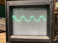
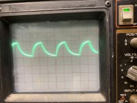
The attached audio file contains audio with distorted sound - or rather it might be more correct to say that the sound is distorted by some kind of interference. I have tried 4-5 tapes - but the interfered sound is there no matter wich tape I use. The tapes are ok - so my deck seems to have an issue.

The interfered sound is present no matter how I playback the tape or how I listen to the recording:
Output connected to amplifier
Output from head phones
fwd or rev pb
Low speed or high speed
DBX in or out

I can also add this:
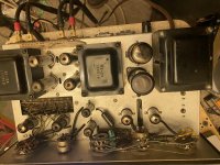
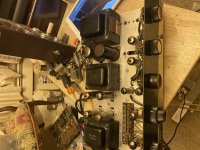
First time I discovered the issue - I removed the lower buttom plate on the back of the deck - and the sound was then ok again. But after that I placed the buttom plate again - the sound was distirbed again.
But after this the issue remains even if the lower plate is removed.

I have cleaned the output potentiometer - and checked wires and solder joints - but have not found anything wrong.

Are any of you able to tell what could be causing the interference heard from the attached file?

BR Benny

Attachments

  • sound-1.mp4
    479.1 KB

  • Locked
Original Maplin 150 Watt Mosfet Module

I have a few Original Maplin !50 Watt Power Amp Module Kits for sale.
I found this old page on-line showing these and they are the ones like mine)
( Mosfet Amplifier (EMM Jun 81) )
Please note , each kit is complete set of components with PCB to build one mono Power Amplifier ---- Two are required for Stereo plus you will need a transformer PSU - 48-0-48 volts Dc

I purchased these with the intention of building some active loudspeakers as well as Power Amplifiers. Due to retirement I may sell if anyone is interested.
They are Brand new and in original boxes.

(These are now sold)

Attachments

  • Maplin 150 Watt Mosfet Amplifier Module Kit.jpg
    Maplin 150 Watt Mosfet Amplifier Module Kit.jpg
    173.4 KB · Views: 1,818

Capacitor I.D

Found this little beauty in my collection.
Just curious in what it is?
I’m assuming it’s a motor run cap or a motor start cap?????
So I tried looking up the specs but there’s not much about it that states if it’s a run or a start cap.
Any info would be greatly appreciated for my future projects😱

VU Meter Problem w/ too much resistance

I have a Teac A-4010s Reel to Reel that my father in law gave me that I have been fixing and restoring. I am not an expert on repairing things, but I am very handy and have some limited electronics experience (and very good luck with fixing things). I have fixed everything except one problem that is bugging me, but not a must fix item. The left channel VU meter is receiving a very small signal. So for example, the right will be getting 0.3v and the left will be retting 0.01. I do not think the meter is the issue because during start up both meters rise to the same level and drop in sequence. I have found the schematics online for a similar model and it looks like there are some resistors that could be at fault (maybe providing too much resistance?), but I don't believe those go bad, so I would assume a cap might be going bad, but I really have no idea. Any ideas? The onboard amp has impeccable wire management, so I have not taken it out of its case yet to try to follow the wires at risk of screwing that up. Just looking for some ideas before I dive deeper.

Current SOTA in measurement microphones?

Hi all-

Looking to buy a truly superior measurement microphone with an emphasis on excellent impulse/time domain behavior.

The B&K 4133 was the hot product way back in the 70's, but I do not know what mics are in favor now?

I looked at the B&K (and also DPA) sites and did not really find *any* mics listed for speaker/room measurement. Do they no longer make mics for this use or did I miss it somewhere? Where else should I be looking? Thanks.

Rectifying Buffer for Transfomer question

Hi,

i might wonder, is there a rule of thump how much you should have as cab buffer for a certain amp or at least what a certain minimum one should not undergo?

I am planing an 2.1 amp with two sure boards, based on an IRS2092, one board we'll be in stereo the other in btl. The idea was to either get two 500va transformers for each board one, or get one 1000va for both, to get enough headroom.
The stereo will have like 2x125 watt at 8 ohms the BTL 500 watts.

So now i was wondering how much capacitance, should i use on the rectifying board to avoid any issues.
Somewhere i heard years ago that there's might be some unspoken rule like for every 100 watt one should have like 10000µf of capacitance...but clearly thats not that case on most amps one could see.
So because of this, i ll try to get like an idea would could or should be usefull.

Woud be nice to get some informative replies. 🙂


Greets Swany

New and Used 300B tubes - Moving Sale

Hello, in preparation of upcoming move overseas, I decided to part with a stock of new and used 300B tubes listed below:

Shuguang Black Treasure 300BZ: three matched pairs (MPs) two new pairs (bought as spares and never used), one pair used for about a year. Purchased from PartsConnexion.

Shuguang 300B: two MPs, one new (bought as a spare and never used), one pair used for about 9 months

Sophia Electric 300B: one MP used for approx. 6 months

JJ 300B: one MP used for approx. 6 months

Euro 500 for all of the above + shipping costs.

Attachments

  • IMG_1540.jpg
    IMG_1540.jpg
    1,019.7 KB · Views: 300
  • IMG_1542.jpg
    IMG_1542.jpg
    974.1 KB · Views: 296

Help with Philips CD960 (CDM 1)

I have a Philips CD960 (basically the same as Marantz CD94mkI) which plays discs/albums with an average runtime perfectly fine but won't play the last few tracks on albums with an unusually long runtime.

So, to give a typical example if I play the compilation album Beatles 'The Singles' which has 27 tracks and a runtime of 76 minutes it will start skipping and stop playing at around track 22.

This particular player came to me as an abandoned repair from a used HiFi dealer and someone had obviously been messing about with it before I got it so all bets are off when it comes to adjustments!

So far I have:

  • Cleaned the upper lens surface
  • Installed new belts and lubricated the mech
  • Lubricated the platter motor
  • Replaced the electrolytics on the small PCB under the mech by the motor.
  • Recapped the main PCB which includes the raw power supplies

I have measured the laser power by means of measured the voltage across R309 as shown in the service manual. The service manual specifies 575mV +/- 75mV and I found the laser power was right at the upper end of the acceptable level so I have actually reduced it slightly to 600mV when playing a good factory CD (about 535mV when playing a CDR).

I have also tried to adjust the focus which I understand is done by raising or lowering the platter height and adjusting for as close as possible to 0v at the brown/white wire on the 6 black 6 pin connector coming off the motor PCB. I have found that adjusting this precisely is very tricky because the reading fluctuates up and down constantly and the optimum adjustment seems to be different for different discs.

I have also tried adjusting the swingarm alignment because I got myself convinced that this was the problem. I did this by slackening the two screws which hold the baseplate of the lower swingarm bearing and adjusting it by hand whilst observing the RF eyepattern. I have simply set it to give the best looking trace at both the start and end of a disc.

This is the RF eyepattern (probe connected to TP65 C501) when playing a good factory CD. The scope is set at 0.5v/division so the pk-pk amplitude is about 1v.

P1110258 by Michael Pickwell, on Flickr

And this is the same but with a CDR which gives about 0.8v.
P1110259 by Michael Pickwell, on Flickr

The photos make it look better than with the naked eye and in reality the trace is a bit blurry/fuzzy for my liking.

I haven't yet recapped the servo control PCBs.

I'm really not sure what to try next and any advice is most welcome.

Skar Audio 4500.1D

Here is what o get on all 4 banks for the power supply fets .

Scope set to 5us 5volts/div

0.1 cap connected between gate and source

Do these appear to be good or do I have bad drivers ?

Attachments

  • 39634146-3F55-4283-8E38-E4F45B524274.jpg
    39634146-3F55-4283-8E38-E4F45B524274.jpg
    998.5 KB · Views: 89
  • 43DA25DA-CD9D-4660-94D8-F73591D410BD.jpg
    43DA25DA-CD9D-4660-94D8-F73591D410BD.jpg
    992.5 KB · Views: 87
  • E6FEB7C3-2587-4F81-9493-E5EAA4118700.jpg
    E6FEB7C3-2587-4F81-9493-E5EAA4118700.jpg
    984.3 KB · Views: 84
  • B1EFC064-9F5E-4477-9A08-CBB656D23E85.jpg
    B1EFC064-9F5E-4477-9A08-CBB656D23E85.jpg
    988 KB · Views: 88

Electro-harmonix Deluxe Memory Man

So, I've been digging out audio stuff in my basement and fixing it up to keep myself occupied during the pandemic (better than drinking) now that my musical performance career is either over or on hold. I came upon my old analog delay unit the Electro-Harmonix Deluxe Memory Man.
Got on the web to do a little research and realized it's the holy grail of analog bucket brigade delay effects unit still in use 40 years later. In fact the "Edge" in U2 uses it often to create some of the more iconic guitar sounds we all love.
I have one of the second generation "big box" ones, especially collectible, made in 1980 according to the pot codes. Folks are selling these for about 1K$. I bought this one in 1981 for $60.00.
I do recall how rich a reverberation sound this had when i played my lap steel through it in the 80s.
Anyway....I looked up a schematic for it and to my surprise this thing is notated in non-conventional current flow, that is the Plus rail is zero volts and the minus rail common is -15v!
I don't know about you but this disturbs my sensibilities.
Have you found any other equipment schematics notate this way?

Krell KSA 300S

Hello gentlemen. I've been searching for another McIntosh MC-2500 to go with the other one I now own. Problem is that I've been unsuccessful in finding another one for sale.
However, I came across a Krell KSA-300S for sale in Delaware. I've never owned a Krell amp before, but heard that Krell owners have been pretty satisfied with theirs. If there are any satisfied owners of this amplifier, please let me know. I'll be very thankful to hear from all of you vintage Krell officianados out there. Sincerely.

Amp distorting from PWM generator

I'm trying to build a standalone tone generator- amp - speaker device.

I'm using the following:

1) PWM Pulse Signal Generator from ebay.

2) TPA3110 XH-A232 30W+30W Class D mini amp.

3) Tectonic HIBM65C20F-8 full range (up to 20khz) 8ohm speaker.

4) Variable DC power supply.

5) various fixed carbon resistors


What I get out of the speaker is clicking sound, along with the pwm frequency sound.
and also when turning the amp on, for first 3 seconds there is am-radio-like distortion.
I'm supplying 14V to both
since the amp can operate in 8V-26V DC range,
and PWM generator in 3.3 - 30V.

I dont have a potentiometer currently, so i tried 10k, and 20k resistor between pwm generator and amp input, in series on the "+" terminal.

Marantz 7C Mystery Resistor

Hi all,
I've finally collected most parts for a modified 7C clone build and have mostly finished with the turret board and tube socket aluminum sheet metal frame.

I have a question for anyone familiar with the preamp's circuitry after seeing numerous photos of the circuit board's resistor side. While the original 7C schematic shows a 1M resistor going from grid to ground connected to V1 and V2 terminal #2, after viewing dozens of photos showing the board, the 1M resistor is evident for V1 (R62B) but R62A is missing on V2. Since V1 and V2 are a and b side first stage circuit mirror images, both tubes should show the resistor in the same spot for both tubes but is clearly not the case. Even looking at the 7K kit version instruction guide, the circuit board graphic shows V2 missing R62A. You will see 6 resistors attached to V1 and 5 to V2.
I'm not worried about how I will construct the circuit but is a bit troubling why they would use two different locations for this resistor when all else is symmetrical.

Would love to hear if anyone else has caught this and knows where the mystery resistor is physically located.

Attachments

  • R62A.jpg
    R62A.jpg
    98.6 KB · Views: 330

Heathkit SA-2 amplifier

Hi Folks
Has anyone ever modded one of these amps? They are actually quite good for what they are. This amp is the stereo version of the UA-1 or UA-2 mono amps while it also has a preamp and phono section. The output iron is ultralinear and the circuit of course uses the tri/pent 6AN8 which I like.
It's no Sherwood S-5000 but I see some potential in this little gem. I also have the AA-151 Heath Integrated which is very similar as well.
I did change the input filter cap and added two more sections underneath.
I didn't change the coupling caps yet but what I am going to so a partial film cap supply and put in a modern selector switch. There are two separate 6.3v taps and it does use a hum pot for each channel but I was going to do DC fil for just the phono and preamp tubes.
Has anyone modded one of these with a separate choke along with doing the tweaked RCA phono stage? Maybe Eli can jump in.

Attachments

  • X90xjiGVTLSLLw7ABNphmQ.jpg
    X90xjiGVTLSLLw7ABNphmQ.jpg
    1,017.1 KB · Views: 554
  • Ab01oi+uTJ+Bs6aDXTuixA.jpg
    Ab01oi+uTJ+Bs6aDXTuixA.jpg
    1,020.3 KB · Views: 460
  • sa2schematic.gif
    sa2schematic.gif
    89.7 KB · Views: 551

NS 670 yamaha speaker xo

I’m trying to rebuild the xo’s on these the electrolytic shunt caps are nippon chemi con cep series 50v (llong gone) nearest replacement in size/type/value is these https://www.mouser.com/datasheet/2/420/united_chemi-cn_04292020_SNX_Series-1842193.pdf but unfortunately they haven’t been manufactured yet! 17wks out is the estimate.
There is no real good replacement except for them except the m.d.l. series (jantzen) which are axial and going to be a pita to mount.

Need two 18uf and two 47uf N-P

Any ideas/help would be appreciated.

DAC repair specialist recommendations.

In my ongoing audio clear-out I am hoping to find a repair specialist to fix a Tube Technology Fusion CD-64 player. These are nice things, the DAC is a 64 tap WATT Dac (as also used by Chord in their DAC64 etc) mated to a tubed analog output stage, and a bog standard easy to source mech. As far as I am aware it was designed by Zia Faruqi. Zia who is now, Vice President of Engineering & Design at Manley Laboratories, Inc.
It would be great, (due to shipping costs and potential for damage) to find a tech in the U.K but I am open to all ideas.
Thank you in advance.
Stay Safe.
Richard.

Attachments

  • Tube Tech Fusion 64.jpg
    Tube Tech Fusion 64.jpg
    50.8 KB · Views: 88

GB: Round #6; Fo-Felix AC Filter

**We're on round #6!!!**


So over the years people have asked about the old version, made by someone else.

It's probably time for an updated one. This one is a bit different. You may notice it does not have following capacitors after the choke. I have tried both ways, and my preference is strongly without the following X2 capacitors. Also the capacitors prior to the choke are not varied in size because overall capacitance is more important - and they won't randomly resonate with each other.

The other major change is the addition of bypass resistors for the chokes. These don't ruin the filtration, but they do a good job of quieting the chokes that can get excited by different combinations of things on the mains.


Fo_Felix_R2_Public_preview2.png


Gen1 w/comoco's
IMG_1974_1_22.jpg


Here's how it is different in settling time from the original.
Fo_felix_vs_felix.png


Here's a comparison between resonances.
Fo_felix_vs_felix_resonance.png


*2oz copper PCB (1oz is standard)
*Weco 983ZD terminals, copper alloy and can accept 2 wires for daisy chain. These are also safer, particularly if you use solid core wire that otherwise likes to make cold solder joints you can't see.
*X2 rated capacitors for safety, 4x 0.47uf. They are alternated for CFC (capacitor field cancellation).
*Discharge resistor for X2 capacitors
*Coilcraft Comoco choke w/fuse or Bourns 8120/8121-RC choke w/o fuse & 15/16A/20A(*) max sockets
*Fuse clips are beryllium copper (good for 30A)
*120/230v operation (parts & pcb)
*Mounting holes are sized to work nicely with M3 screws and standoff kits
*Size: 2.25x4.25in

The Weco 983ZD are preferred terminals, but not always available as individual sale. For this reason I'm going to include them in the price of PCB, so that I can meet min order requirements for them and save everyone the shipping.

Price: $13ea ($9 per filter board same as original, $2 per Weco, 2 needed per board)

Shipping: $8.50 US, priority USPS box
$15 CAD
$16 General international padded envelope
If ordering over 4x boards there may be an additional $10, depending on destination.

Need 32 filter board commitments to order.

schlomoff 4
luisb 8
Joca 6
jtmsrl 2
afoor 4
vinylvalet 6
codyt 1
chiily 2
Derekva 2
ikir 10
jamayfie 2
Dadbeh 2
ipolyakov 2
Albrerta 3
KevinHeem 2
Skip Pack 4
amandarae 2
dualuxe 6
jameshillj 2
Bennyboyph 4
OldF 4

Anyone ever blown a speaker cable??!!??

Sorry for the caps and the ridiculous question but I'm stuck on solving a problem.

About to sell some speakers so thought I'd hook them up to check as the person is coming tomorrow.

right channel doesn't work - panic that I did my first bad refurb!

Swapped speakers around both speakers work fine on left channel.

Turned speaker switching unit to other room - both channels fine.

Wonder if it's a problem with switching unit channel for this room. Switch cables around on back of switching unit, again other room works fine this room right channel still bad on my normal speakers and the ones I'm selling.

Check right cable for signs of damage - none.

Write post here with ridiculous question..someone please help!!

What part of DIY do you LOVE?

Well, I'll keep it at this but the hate-thread really needed a counter-balance..

I'll go first (is this a more difficult question?)

- !!when an amp is finished, measures fine from the start and sounds great (with very low hum, please)!!

- first contact with ordered parts, cherishing tubes in stock, hell, even transformers and oil-caps, it's a materialistic thing.... Buying things...

- psudII

- looking for a promising circuit with tubes and parts I already have

- Increasing knowledge and know-how

- The 'artistic', visual aspect of creating an amp

- Tube-rolling

- Deeper appreciation of music through better sound (sounds corny but you know what I mean)

- The struggle, the road behind me and the road ahead.

Bed-time

Simon

wiring volume control

How do most of you wire up your volume pots? Do you use shielded wire? And if so do you run the shield to ground with its own wire from the input end or do you run the signal return on the shield and connect it at both ends?
I am using a pcb with a big ground plane on it so I am running all my grounds to this like a star ground. Should I run the shield as a signal return and use it to carry the ground from the rca to the pot. then from the pot to the pcb input?
Or run the rca ground straight to the pcb and skip the pot, running a wire from pot ground to the pcb?
And do you connect the shields to ground with a seperate wire or do you use them as a signal return? I have seen it both ways.

High Level Input into Amp?

Hello guys,
I finished building my C-Note speakers but am a bit unhappy with the low-end so I want to build a subwoofer.
I am planning on using the Dayton SD215A-88 Driver for it.
My current amp is the Sony STR-DH100 which unfortunately does not have a sub out, so I am looking for a subwoofer amp for the Dayton Driver which can use High Level input from my STR-DH100.
Is this even possible with Class-D amps? If so id be happy about some recommendations. 🙂

Best Eminence 12" woofer for a sealed SEOS Speaker

I'm building a new studio for myself - I work in the music business... (approximately). I've had built a 4Pi and an Econowave... both to my satisfaction... but I know little about the science...

The new system will be externally crossed over with a 2 x 6 DSP unit, and tri-amplified.

Eminence speakers are available very inexpensively, where I'm at... I want to find the best 12" woofer to put in a sealed cabinet, crossed over around 1.2 KHz to a CD in a 12" SEOS waveguide... a fair bit of real estate is available... so I'm trying to stick with WinISD's default cabinet recommendations, being that it surely knows more than I do, about cabinet optimization.

I modeled every 12" speaker that the Eminence website recommends for sealed boxes, and the Delta 12LFA came through, by far the best -> -3 dB @ 80 Hz in the recommended enclosure (2 cu. ft.)... Attached, you can see simulations of the other Eminence drivers popular with the SEOS guys - the Delta Pro-12A and the Definimax 4012HO - neither models as well as the Delta 12LFA...

So whats not to like about the Delta 12LFA - why is it so suspiciously cheap ($90)? Why should I consider the Delta Pro-12A ($135) or the Definimax 4012HO ($215) over the Delta 12LFA? I'm certainly not trying to scrimp on this expense - I'm going to be spending a lot of time on these...

I'd posted similar questions on the AVS forums, as it seems to be home to all things SEOS - but I didn't get much traction there... trying again here...

Thanks in advance...

Attachments

  • Eminence Choice.jpg
    Eminence Choice.jpg
    32.1 KB · Views: 1,602
  • SEOS Room.jpg
    SEOS Room.jpg
    76 KB · Views: 1,419
  • WinISDEminence.jpg
    WinISDEminence.jpg
    125.2 KB · Views: 1,414

QTS Method vs EBP for Full Range TangBand

Hi, I am currently designing a speaker for my bedroom. I have read many post regarding to speaker compatibility in sealed or closed encosure and saw two different method for calculating it. Some say QTS >0.5 is better for sealed and some say EBP <100 is better for sealed.

My problem lies in the current driver that i own where the QTS is 0.641 but the EBP is 130-ish. My question is, better sealed or ported for my driver in small listening room (bedroom TV)? Keep in mind that the speaker will almost have no gap to the walls (approx. 1-2cm).

I have modeled it on WinIsd, and on the ported enclosure the cone excursion is more than 10mm below tuning frequency (20W Input). Is the WinIsd cone excursion simulator accurate? As i am afraid to damage my drivers via over excursion since i don't know what the Xmax rating of my drivers are.

Help is appreciated, many thanks!

P.S. I attached the driver files obtained via TangBand

Attachments

FS: Dallas II Speaker Cabinets

**SOLD**

This is a pair of Dallas II back loaded horn speaker cabinets. These are not small and not light so local pickup would be required. Great birch ply construction. The internal wiring is in place but will need binding posts. Making sure they find a good home and are enjoyed is more important than seeing how much I can get for them.

Price: $50
Pickup Location: Grand Rapids, MI

Attachments

  • 1.jpg
    1.jpg
    60.2 KB · Views: 434
  • 2.jpg
    2.jpg
    65.1 KB · Views: 435

SMD soldering flux.

What SMD soldering/desoldering flux do you use and suggest? I have watched YouTube videos by Louis Rossman doing literally next to impossible SMD desoldering/soldering work, but I have no idea what flux is used. I remember several years ago, I tried to repair an SMD PCB and failed miserably. The FLUX seems to be of paramount importance, and the internet is a nest of vipers ready to bite the innocent. The flux I ordered online was fake. It was much like wax used to steady components in old radios, rather than SMD flux!

SMD soldering would be a feat, but I am daunted by the thought alone!

LateSit

Without Mr Pass and many contributors to the Pass Labs Forum, I wouldn’t have a clue what is concerning a class A SIT audio amplifier.
Those information helped me to build an SIT amp with a complementary lateral mosfet, my LATE - SIT

Point to point wiring I finished the power stage, which included an BUZ905D and an THF-51S.
The driver stage at the moment is an 8 dollars EBay 6J1 tube preamp, will be modified for best coupling to the gates.

YouTube

Attachments

  • 7B86C359-CD62-4867-B7EF-09B5B5D4FA9A.jpg
    7B86C359-CD62-4867-B7EF-09B5B5D4FA9A.jpg
    806.1 KB · Views: 2,122
  • 6ABA3163-7611-45DD-B13E-6933368E287F.jpg
    6ABA3163-7611-45DD-B13E-6933368E287F.jpg
    845.7 KB · Views: 2,030
  • 42A5E13E-0645-48A5-AE4F-50E858CA8EBF.jpg
    42A5E13E-0645-48A5-AE4F-50E858CA8EBF.jpg
    668.3 KB · Views: 1,961
  • C216A5C6-2ABA-4404-BB1D-24B85B8C1106.jpg
    C216A5C6-2ABA-4404-BB1D-24B85B8C1106.jpg
    720.3 KB · Views: 2,313

FS: SEAS Excel W22EX 8" Woofers

For Sale: SEAS W22EX TV-NHT. These are used out of NHT speakers. Identical to SEAS W22EX except phase cone replaced by dust cap and a shield covering the magnet. I have six available. Asking $200/pair OBO plus shipping and 3% paypal fee. Local pickup available.

Attachments

  • 20200725_122455.jpg
    20200725_122455.jpg
    393.1 KB · Views: 523
  • 20200725_122503.jpg
    20200725_122503.jpg
    279 KB · Views: 514
  • 20200725_122516.jpg
    20200725_122516.jpg
    470.1 KB · Views: 501
  • 20200725_122532.jpg
    20200725_122532.jpg
    385 KB · Views: 503
  • 20200725_122536.jpg
    20200725_122536.jpg
    325.4 KB · Views: 495

experiences with ESL directivity?

I'm interested in hearing about the successes or failures others have had with trying to make electrostatic loudspeakers (ESL's) with something approximating constant directivity (distribution of sound independent of frequency). Here "constant" directivity means the speaker has the same dipole radiation pattern from a few hundred Hz on up---the pattern doesn't grow narrow and pick up more lobes as the frequency increases.

For practical and theoretical reasons I'm inclined to avoid curved panels (sections of an upright cylinder). Since I'd like to make something a bit narrower than the 20"-wide ESL/dynamic woofer system I now use, I don't think approximating a cylinder with multiple flat panels would do the trick either. That leaves me feeling that a narrow, tall tweeter, flanked by wider midrange sections, etc. would be the way to go, but of course there are many ways that could be implemented.

The other alternative might be a cylindrical version of the Quad ESL 63's point source approximation. That would involve delay lines so the signal emanates first from a narrow, tall central section of the diaphragm and then emanates from regions progressively farther from that central section. I'd be inclined to try to do this actively but I'd have to come up with a low-cost amplifier/transformer scheme that I could afford to duplicate several times--once for each delayed section. I believe it was Bill Waslo who showed that cheap transformers can be used to drive small sections of ESL panels. I haven't yet tried to duplicate his results. I also have yet to complete my chip amp project so I haven't tried it with a capacitive load. I'd be interested in finding out if one of those would tolerate a very narrow section of a larger ESL panel. Even if the amp and transformer details could be worked out, there's still the pain of making sectioned ESL stators, but I guess I'm going to run into that no matter what I do.

The tweeter/midrange approach certainly seems cheaper and simpler. Anyway, I'd like to make new mistakes instead of repeating old ones so if anyone has experiences or insights pertinent to the problem of controlling ESL directivity, I'd love to hear about them. BTW, I'm more likely to do another hybrid system rather than trying to go ESL fullrange.

Thanks in advance.
Few

Odd instability in LTspice simulation

I'm modeling a tube amp power supply that uses a capacitor multiplier for B+ and a capacitor-coupled bias supply.

flompWO.png


With the bias supply disconnected, I get a nice, clean B+ with about 3mVpp of regular, sinusoidal ripple.

With the bias supply connected and a load of 134mA, that ripple is superimposed on a pinkish noise signal that ranges about 100mVpp.

19qguJW.png


If I lower the load just slightly, to total 132mA (what's shown on the schematic), it's noisy for around 33 seconds, then smooths out perfectly:

1NBwZbx.png


I can reduce the "convergence" time down to about 14.5 seconds by tweaking to 132.29mA, but that's as fast as it can go.

wse5wL6.png


I can't think of anything in this circuit that would cause this behavior - either it should be unstable/noisy, or it shouldn't. Why would having a very specific load - with precision in the tens of uA - cause it to be more stable? This feels like an LTspice artifact, but I'm relatively new to it.

The only non-stock component is the IRF840, which uses this model:
Code:
.model IRF840   NMOS(Level=3 Gamma=0 Delta=0 Eta=0 Theta=0 Kappa=0.2 Vmax=0 Xj=0
+      Tox=100n Uo=600 Phi=.6 Rs=6.382m Kp=20.85u W=.68 L=2u Vto=3.879
+      Rd=.6703 Rds=2.222MEG Cbd=1.415n Pb=.8 Mj=.5 Fc=.5 Cgso=1.625n
+      Cgdo=133.4p Rg=.6038 Is=56.03p N=1 Tt=710n
+      mfg=International_Rectifier Vds=500 Ron=850m Qg=63n)

  • Locked
FREE: New/NOS Hypex UCD32MP with OEM cable set. YOU PAY SHIPPING

ALL SOLD ALL SOLD ALL SOLD ALL SOLD

Read Carefully.

I have x4 new, sealed in box Hypex UCD32MP modules. And x4 cable sets.

Specs: Hypex Electronics B.V.

2 can fit in one USPS Priority Mail box.

I am only asking $20 per box (one or two modules per box) for shipping and handling via USPS Priority Mail and PayPal fees.

Nick

McIntosh MC502 transformer rebuild

Hello to the Forum


Some months ago I bought an all original McIntosh MC502 power amp, untouched. Yesterday I finally had the time to unpack and test it.
Althought it works perfectly, apart from the L channel protection "Normal" indicator which seems burnt (I'll investigate on that soon), the main problem I have is the transformer buzzing...very annoying.
I plan to use this amp in a mini setup for my working desk, where I always keep the volume at minimum. Humming and buzzing is something I cannot live with. I already fired a Cary SLA-70 for that.


I've tried to access the transformer to see if it was possible to tighten the laminations screws but it is completely buried in resin. No way to go, unless using brute force, which is something I'd like to avoid, since the box is well finished, with McIntosh logo and connections legend.
Trying to insulate the chassis from the trafo box did not help.


I am now wondering whether it would be possible to completely remove the resin+trafo and replace it with a modern toroidal one. In this way the look wouldn't change (maximum attention shall be to put in order to avoid damaging the trafo box finish) but it should go completely silent and, possibly, with slight better current delivery.


Did anybody ever try something like that?

Do you guys believe it is feasible?


Thank you


Bye


Raf

40watt P-P tube amp parts

40watt P-P tube amp parts I am selling the following unused parts which were intended for a P_P monobloc amp as I have decided to go parallel KT150 SE.


1 pair of Hammond 1650H OTPs £180 for both inc UK shipping

1 pair of 230v mains transformers, 350v 400ma (not ct) + 6.3v 3.2a UK made. £100 for both inc UK shipping

4, off 6L6GC matched quad JJ/Tesla from watfordvalves.com £50 the set

4 off KT77 matched quad JJ/Tesla from watfordvalves.com £50 the set

Valves have never been out of the packaging.

Thanks.
Ian

Linear power supply - two windings or linear voltage regulator

Hi,

I am inexperienced and have found myself questioning the need for multiple linear power supplies, or a single power supply with multiple output rails.

If I needed 12V 10A to power a computer motherboard for a music server, then if you wanted add in an additional PCe 5V 2A Audio card. Provided it's still within the capacity of the linear power supply, then it would be much cheaper to use a linear voltage regulator to drop the 12V down to 5V... such as DIY KIT LT1083 High Power Linear Variable Regulated DC Power Supply Board Kit-in Amplifier from Consumer Electronics on AliExpress - 11.11_Double 11_Singles' Day

Does this work well? Why do many solutions involve the use of multiple separate linear power supplies, with separate windings, different rails and so forth? Other than the heat generation, is a linear voltage regulator a very cost effective solution?

Thanks

Better Audio by Running all Aleph Power Amps in Inverted Mode? only for Unbal Preamps

Better Audio by Running all Aleph Power Amp Devices in Inverted Mode (only helpful for Unbalanced Pre-Amp Outputs) ?

I have heard from some owner's, that the inverted mode brings a better sonic quality than non inverted mode (as long as no preamp with balanced output available).
In cases, where is a balanced XLR input socket was provided like on devices from early Aleph series, this is an easy task to investigate by soldering a corresponding terminated XLR plug instead of the existing cinch plug on the coax lead - go to the schema of first PDF file.

If only unbalanced input on power amp is present like model Aleph 30 - to find in the schematic of second PDF file, a bit more effort is necessary for changing from non inverted to inverted mode.

What listening experiences in inverted mode were made here ?

Attachments

The Mu Monster

Elsewhere on the forum our friend Rob (n3szd) wants to build a 1000 watt
single-ended amplifier.

On the one hand, I sympathize with excess enthusiasm in a project.

On the other hand, I take no responsibility for the results of posting the
following schematic.

Anyone who attempts to build such a thing is probably asking for trouble.

You have been warned...

😎

Attachments

  • MU MONSTER.gif
    MU MONSTER.gif
    335.1 KB · Views: 4,173

Help needed understanding this prepreamplifier

Dear members,

I have recently acquired a fantastic sounding prepreamplifier from way back in the eighties; Electrocompaniet MC-2. An all class A device originally marketed as having a self-sensing system for detecting optimal load on cartridge based on current flow.
The idea was said to improve headroom and dynamics. The load and feedback was set through resistors (using dip-switches).

My unit is a later one with exchangeable resistors for optimising load and gain. My problem is, I simply do not understand how it works!
Ideally I want to be able to adjust MC-2 to any chosen cartridge. But how....?

I hope the community is able to shed some light on this 🙂

How is the load resistor correlated to the gain resistor?
Do the cartridge only see the load resistor value or is some of the circuit part of the total load seen by cartridge?

How to calculate and adjust gain using feedback resistor? I guess the feedback resistor value is dependant on the load resistor, but otherwise I have no clue.

I found a drawn schematics on the internet which correlates well with my unit except for trim resistor setup for feedback/gain. I have only a fixed resistor in mine.
This is for the first version with load resistor being (maybe?) 10 Ohm on input.
Feedback/gain reistors made up from trim resistor in series with 160 Ohm; both in parallel with 2.7 kOhm. This should result in values between 151 Ohm and 393 Ohm.

Attachments

  • Screenshot 2020-11-22 at 10.30.21.png
    Screenshot 2020-11-22 at 10.30.21.png
    750.3 KB · Views: 873

FS: PCBs for most usable blocks (like PSU, modelling boards, OpAmp and tube stages)

Good afternoon.
Do you remember such a usual case: you often need any very necessary for a most kings of audio projects, such as PSU, level indicator, tube stage, special prototype board etc.
Recently I've got delivered from the factory the set of PCBs, which I designed.

A few exapmes of using (the end of thread) and new modifications

_DSC4704.JPG

_DSC4702.JPG


I've done these as much as possible universal: PCBs have mask, serigraphy labels of control points, input/output, king and markers of elements, name and purpose of PCB. Most part of boards has a prototyping area to install extra elements for extending capabilities of circuit.

I've done them for my DIY to save my time. But I am ready to sell surplus of these to you.

List with pictures of PCB layout and price is below.
Price does not include shipping. Please, write to me there or PM or e-mail - number and counry, I'll calculate price of shipping. Shipping from Russia is pretty cheap! )

[*]Simple 2 bridge rectifier - 1 euro


[*]Universal PSU with voltage regulator LM78** series (may set voltage 5, 6, 9, 12, 15В...) - 1 euro


[*]Prototype board for OpAmps in DIP8 - 2 euro


[*]Prototype board for OpAmps in DIP8 with 2-polar PSU - 2 euro


[*]Power supply +48V with diode voltage multiplier to be used with condencer mics (read article in my blog) - 2 euro


[*]SRPP tube stage with rectifieng voltage for heating; tube king 12AX7 - 1.5 euro


[*]Two SRPP stages for 12AX7 + prototyping area - for stereo or serial - 2.5 euro


[*]Universal bipolar PSU with voltage regulator LM78** и LM79** (for voltages ±5, ±6, ±9, ±12, ±15В...) - 1.5 euro


[*]Power supply for high anode voltage 100V - 350V with electronic filter - 3 euro


[*]Whole amplifier (modified like in
this article) like Millenium with PSU and relay speaker protection uPC1237HA; especiality - heatsink from CPU mounts on the board - 5 euro


[*]Mic preamp PSU ±15В, +48В - 3 euro


[*]Speaker protect circuit with uPC1237HA - 1 euro


[*]LED level indicator with LM3915N-1/NOPB - 1 euro


PCB does not include elements! Board only! Not assembled!

Esp project 173

Hello,


I am new to the forum and trying make my first pcb out of a schemantic. Esp project 173, Equaliser circuit to the constant directivity horn.


I didnt find pcb anywhere


Project 173


So in the original op amp schemantic U1A, U2a, U3a, U4a,U5a are used for one channel and Rod mentions that "U1B ((U2b, U3b, U4b,U5b) would be used for the second channel"


I only need mono circuit, so should i


- Make circuit for each of the unused op amps


- use the other side of the opamp within the circuit like this
U1A in schemantic would be in my project opamp 1A
U2A in schemantic would be in my project opamp 1B (b side of opamp 1)

U3A in schemantic would be in my project opamp 2A
U4A in schemantic would be in my project opamp 2B (b side of opamp 2)
U5A in schemantic would be in my project opamp 3a
and then make circuit for unused op amp 3B


Thanks in advance!

Attachments

  • p173-f2.gif
    p173-f2.gif
    8.4 KB · Views: 70

CS1676 and CS1677 transistor replacement

So I am going to re cap and replace the transistors in a Realistic STA-76. I have found replacement caps and transistors for everything except transistors on the the main amp board and power board. They are FCS1676 and FCS1677, I have found a few old post on here with couple of different replacements but can't really find the replacements as they are now too old and my with limited knowledge about transistors don't know how to manually search for replacements.
So if any one knows what will please help me out.

Attachments

  • 20201219_184452.jpg
    20201219_184452.jpg
    562.4 KB · Views: 110
  • 20201219_184600.jpg
    20201219_184600.jpg
    639.5 KB · Views: 94

Speaker distorting, what to look for?

Hi guys,
I've got a Fender Passport which has got one woofer distorting. I have ruled out all the possibilities (check by connecting to the two outputs of the amp, connected the driver to another amplifier directly and the driver still distorts).
I have looked for the common causes like tears, coil rubbing, foam rot etc.
I couldn't find any tears or any place which has 'unglued'. I moved the driver gently and can't hear any coil rubbing tapped on the driver and it sounds normal (like a drum).
When I play a sine wave through at very low volume it sounds ok, but as soon as I increase the volume even slightly it distorts and the sine wave sounds like a square wave. I tried gently pressing around the surround while playing the sine wave can't find a 'spot' which makes the distortion go.
I understand the driver is pretty much busted and the only option would be replacement or re-coning, but I would like to know what exactly is wrong any other things I should look for and check?
When it comes to replacement - its a China made Celestion t5919a, I couldn't find any place to source it have send couple of emails yet to hear back. I was only able to find used drivers on ebay.
Also for future reference - would an issue with the crossover network cause this kind of buzz/distortion in the woofer?

Thanks in advance for the help.
P.S I have attached a photo of the place where the cone is glued to the spider - there seems to be less glue at one point, I doubt that this is the problem but that's only what I could find.

Attachments

  • Speaker.jpg
    Speaker.jpg
    581.1 KB · Views: 133

What design for a pair of 12" Goodmans 401 ?

So I saved a pair of Goodmans Axiom 401 and I'd like to give them a second life but I've found very little info on them and I've no idea how to proceed.

From what I understand from this page, they suggest a 50l sealed box. Does that make sense ?

It's a big full range and while the top range officially extends to 12khz they apparently really needs help in the highs. Any suggestion for this ? Should I cross low with a horn to try to match directivity or just slap a super tweeter on top ?

Many thanks in advance to whoever has an idea on how to get this started. 🙂

Made a crossover Booboo

Fixed it tho.
Making an outboard XO for my garage set to add in a decent woofer. Did some quick and dirty figuring and went to the parts boxes to get stuff.
Found some nice 10uF Vistaon caps in a box of donated parts and thought to myself "Bewdy mate, no need to drive to town and spend $20-"
Soldered everything up and put everything together and the sound was awful. Distorted and strained and painfully loud at the XO frequency and out of sinc.
Anyway in conversation with the part donor it turns out that the caps were NOT 10uF; but 100uF.
Went into town and spent the $20- and it sounds a lot better now. Thanx Peter.
Just one of those mistakes that are easier to make when your eyesight starts to go wonky at close distances, need new a new magnifying glass I guess.
If anybody is interested it is about 400Hz, 21uF & 4.2mH aircore to the mid box and 5.6mH to the woofer with 10uF and a 15R resister to ground.
Designed with the help of Woofer Box and Circuit designer 6.
Plugged the other cap value into the program and it showed as a huge peak and dip in response and an octave overlap too.

What kind of relay to replace bass boost switch

Hello,
A part of my diy bluetooth and ir remote controlled soundbar project involves replacing bass boost switch on preamp section of amplifier with a relay that will be controlled by arduino.
Now my question is: Is there something that I need to be carefull about when choosing relays? I know that it must be mechanical and not solid state that is not made for audio.
But are there any other things that I should consider?
I will try to get smallest relays possible for pcb.

Thank you

Advice needed for Visaton SC 10 N problem

Hello community,
I am new member here although I visited this site anonymously many times in the past. Thank you for many useful information, tips and tricks and all 🙂
In the past, I built several loudspeakers following known designs. Recently I decided to build Visaton's Clou. It is almost finished but I am having trouble with one of the SC 10 Ns.
I use Dayton Audio DATS V2 to test and measure all my drivers before installing them. I tested about a dozen of Visaton drivers so far but the SC 10 N showed anomalies I did not like - it had triple impedance peaks and did not pass the DATS rub and buzz test. I returned that faulty SC 10 N to the seller and they exchanged it for another specimen which had similar issues. (The "good" SC 10 N I have measures just fine on DATS and passes the rub and buzz test.)
I also talked to Visaton people and one of their technicians suggested I should excite the transducer with a 4 Volts sine tone at drivers resonant frequency (~1500 Hz -to evenly distribute ferrofluid - alleged culprit of the issue). I did that and here is the summary of that experiment:
-Exciting the transducer with sine wave at frequencies at or near its F(s) eliminates most anomalous impedance peaks 🙂
-However, the same transducer subsequently excited with signals carrying other frequencies (including plain music) goes back to its faulty state 🙁
I reported these results back to Visaton and last they said is that those multiple peaks "are not critical" for normal operation. I hear some difference and I also used ARTA and REW to verify my suspicion; the curves for my good SC 10 N and the bad ones are somewhat different. (However, I still do not have a calibrated mic.)
I also do not have experience with problems of this kind and the SC 10 N is sealed so I do not want to temper with it and void the warranty.
Please advise, thanks.

Attachments

  • SC 10 N good (a).jpg
    SC 10 N good (a).jpg
    91.2 KB · Views: 289
  • SC 10 N good.txt
    SC 10 N good.txt
    11.6 KB · Views: 100
  • SC 10 N faulty 1. .jpg
    SC 10 N faulty 1. .jpg
    89.4 KB · Views: 259
  • SC 10 N faulty 2.jpg
    SC 10 N faulty 2.jpg
    87.6 KB · Views: 282
  • SC 10 N faulty.txt
    SC 10 N faulty.txt
    11.6 KB · Views: 59
  • Test.jpg
    Test.jpg
    124.9 KB · Views: 276

Wanted - good clean 10-15 Watt AB stereo amplifier

I need a clean small amplifier to drive a set of transformer-coupled electret headphones. I built an LM1875-based amp and was not impressed - these headphones deserve better. No Class D or tubes. Class A is attractive, but might be too large, so probably an AB design.

The requirements are simple. It's a pretty easy load to drive - see attached plot of the input impedance of the coupler. It's about 20 Ohms over most of the audio spectrum, we can call it 16.

7VRMS is enough to drive the phones to the loudest level I'd normally use, but we can double that for headroom. 15dB of gain is plenty. +-15V supplies should be fine for this. So we're talking something in the 10-15 watt range. A little more would be ok.

Ideas? I'll consider anything from a finished product to a bare pcb to build on.

Attachments

  • FonC4Z.GIF
    FonC4Z.GIF
    9 KB · Views: 412

nakamichi pa7 mrk2

ive been thinking of buying a pa-7 amp for a while now and up pops a mark2 European model.
reading up about it on the web and i found this and i quote,

" They were supposed to just license his STASIS technology, which combines the benefits of Class A amplification without the drawbacks (runs stupid hot = very low reliability) into a hybrid Class A/Class AB power amplifier with optical bias. Well, they didn’t just license STASIS. Rather, the first generation of the PA-7 is a direct copy of the equivalent Threshold amp. A lawsuit ensues, then Nakamichi releases the PA-7II with an altered design providing 25 more WPC (watts per channel) and a higher price tag. But everyone knew then and knows now that the original PA-7 was, “the one to get”.

is this true? is the first model better? or would a threshold s 200 be better for driving yamaha ns1000's speakers?

Ancient Percussion - Rock Gong

The British Museum, How to play an ancient rock gong

"The British Museum invited Dr Cornelia Kleinitz, an archaeologist specialising in rock art, and Liam Williamson, a modern rock drummer, to try and discover how a rock gong might have been played. This was the result.

Rock gongs are a type of lithophone that were used for thousands of years in several parts of Africa. They may have been used as part of rituals, to signal other people, or as a form of expression. Although they look like plain boulders, they have a hollow, metallic sound when struck due to the composition of the rock.

This film was created with the African rock art image project which is supported by the Arcadia Fund."

How to play an ancient rock gong - YouTube

Suggestions for cleaning wood?

More specifically, kitchen cabinet doors. Ugh, mine look nasty, should have dealt with this more comprehensively years ago. Should probably replace the doors entirely but don't want to deal with either the project or the $$$ at this time.

I've sometimes used wet paper towel, then dried off right away, gets stuff off without doing much damage. However there is other caked on sticky stuff from who knows what my wife is doing, and grease residue, and around the knobs/handles I think finger residue. Yesterday I used those anti-germ wipes, they take a lot off, but checking in an unobtrusive spot also not good for the finish, too harsh.

What are better products to use? In particular, those wipes I think have a good texture to get stuff off, is there a non-bleach version of those? And some kind of stuff (Goo Gone?) that won't kill the finish too badly?

Lost a channel

I have an upgraded Audio Innovations Series 500 tube amp. An exuberant nephew bounced a tennis ball off one of the power tubes (an EL34). I examined it - it looked fine but it wasn't. It had a tiny crack. A few minutes into the next playing the valve burnt out (brief bright yellow fire) and this was accompanied by a very significant pop thru the left speaker. The left channel is now silent. Apart from replacing the valves has anyone got any idea what I should look at replacing to get some action out of this silent channel?
Projects by fanatics, for fanatics
Get answers and advice for everyone wanting to learn the art of audio.
Join the Community
507,832
Members
7,890,032
Messages

Filter

Forum Statistics

Threads
406,336
Messages
7,890,032
Members
507,832
Latest member
ELECTROPLUS