Repaired Blues Junior with low B+

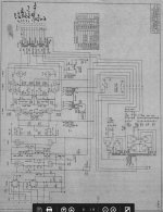
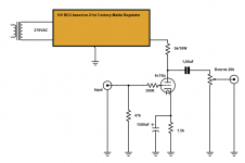
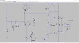
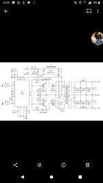
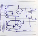
Here's a mystery from my latest project: I've repaired a Blues Junior (schematic attached), and have it working and sounding fine. However, when I measure the B+ voltage, it's far lower (at 255V) than the schematic from the manual suggests I should find it (329V). Other supply voltages are similarly low by >20%.

Before the rectifier, I find 256VAC across the PT secondary as expected, and measure 130VAC at the junction of D1 and D3, which matches the schematic.

Pulling the preamp and PI tubes raises all the voltages a little bit, but doesn't meaningfully change the situation. Pulling the power tubes as well leaves all supply voltages at 350V. So, seems to me the power tubes are pulling the voltages down, and I imagined I'd find them running hot.

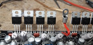
But no: bias voltage measures -10.6V just as the schematic suggests. I measured plate currents via OT resistance & voltage, and found 15ma (1.41V/91.6R) and 14ma, which seems quite low for EL84s — not at all what I expected! Switching to a different pair of EL84s didn't make any significant difference. Just in case something was wrong with my plate current measurements, I tried paralleling some resistors across the bias supply voltage divider (R51 and R52), to drive the bias to a very cold -16V, but even this left B+ at barely 300V.

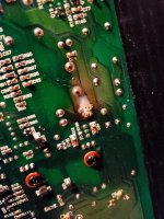
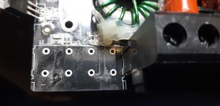
In case it's a helpful clue: the problem I found and repaired was that the first voltage dropping resistor in the power supply, R47, had burnt out. The replacement I installed (2.2k 2w) runs warm, 48C according to my IR thermometer, but doesn't seem to be in danger of a similar fate.

Any ideas on what might be going on? Given that the amp sounds fine and the power tubes seem to have low dissipation, I'm tempted to call this a success, but I'm worried I may be overlooking something that will cause problems.
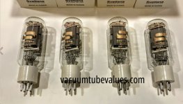
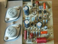
Attachments

New (old) member from UK

Hi,
I'm and ex-Royal Air Force avionics engineer who has practically forgotten all my electronics training.

I'm currently working from home and have had the time to setup a long forgotten Rega P2 turntable and have started to look at DIY amps and power supplies.

I have a TDA7498 amp on the way from China and will look to use some existing PSUs I have.

Looking forward to learning from you.

FS PCBs: UTHAiM, My_Ref Fremen, SS Dynalo, O2, Marsh, Hiraga, M2, SHP XRK

Cutting down on projects, following bare PCBs for sale:

-UTHAiM v1.0 by EUVL; 1 set SOLD

-My_Ref Fremen edition v1.72; 1 set

-SS Dynalo rev 1.1 (with 30x MPS06 and 30x MPSW56 ) by Kelvin Gilmore; 1 set

-O2 Objective2 HPA v1.1 by NwAvGuy; 4 boards

-Marsh HPA; 2 boards

-Hiraga Super 30W rev 1.1 from Jims audio (with 4x 2SA872 and 4x 2SC1775); 1 set

-First Watt M2 tribute (with PSU PCB) by JPS64; 1 set

-Simple High Performance DC coupled class A HPA by XRK971; 2 boards

Any reasonable offer accepted. PayPal or bank transfer

Attachments

  • IMG_20210126_174639.jpg
    IMG_20210126_174639.jpg
    895.4 KB · Views: 232
  • IMG_20210126_174030.jpg
    IMG_20210126_174030.jpg
    990.6 KB · Views: 229

G'day Diyaudio!

Hi everybody,

I'm Ben from Australia, I've been into music all my life and enjoy electronics work as a hobby - this makes a great pairing doesn't it?!

Currently I own circa 70's Solid State gear, mostly Sansui which I like the brand for many reasons.

I carry out restorations, repairs and minor upgrades to amps, recievers and speakers. I'm somewhat limited to my understanding of circuitry though I do learn a lot from here and other places and think that I have a good sense for sonic improvements.

Looking forward to sharing the Diyaudio experience with all of you.

Best regards
Ben

Newark’s house brand Multicomp pro, yay or nay

Hello all, trying to find an answer on this. I have a couple big amplifier projects coming and I’m looking to buy a quantity of outputs. For example if I were to buy the On Semi MJ21193G I could get them in the $6 range. Not a lot, but they’ll add up quick as I’ll need dozens and dozens along with the complimentary device.

Now through Newark I can get the same device labelled MJ21193 made by Multicomp Pro at nearly half the cost. That would be a huge savings. If they’re nearly the same product in quality it’s a no brainer to grab them. If they’re similar to NTE products then I may steer clear. Looking for some guidance!

Thank you,
Dan

Attachments

  • D2A33F76-F17F-4905-A422-B9A72725C994.png
    D2A33F76-F17F-4905-A422-B9A72725C994.png
    920.2 KB · Views: 157

Preamp with tone control

Hi,

Maybe this is not considered high-end, but neither my speaker(s) nor my room has a flat frequency-response.
And sometimes some tracks need more base/mid/treble, whatever.

Well...I've tried to "design" an unbalanced preamp with built-in tone control. (-> differential pair, tone control, mixing stage)

I didn't want to use inductors, so I've tried to gyrate capacitors (=transforming capacitance into inductance, inversely proportional) using FETs.
It's possible to gyrate a capacitor using tubes or op-amps. To keep up the spirit, I want to use FETs, but I don't want to diy op-amps directly (too many parts).

Simulating it with circuitmaker indicated that some of my part's values are wrong. There's no effect on the signal, I think because the FETs in the gyrating stage are not turned on. And there's no gain.

The idea is to use the balanced zen pre as a differential pair, tone control with gyrated caps instead of inductors and a simple mixing stage (mixing the pure signal with the tweaked signal).

Maybe someone can help me fix the circuit.


Yarr, Dave

Attachments

  • zen_eq.jpg
    zen_eq.jpg
    58.6 KB · Views: 1,136

Dayton Audio DCS205-4 Box sizing

Hi!

I'm building a subwoofer for home cinema. I have fronts with nice low end (40-50 hz), so what I want to extend the bass to 25-30Hz.
This is budget diy project, so I've chosen the Dayton Audio DCS205-4 which is around 100USD here in Europe.

I'm plannig to have a 42l (1.48 cf) reflex box, with a 29Hz port tuning.

Will this work with a 100W rated chinese D amp around the 30hz range?

Thanks!

Attachments

  • dcs205-4_data.PNG
    dcs205-4_data.PNG
    28.6 KB · Views: 250
  • dcs205-4.PNG
    dcs205-4.PNG
    34.8 KB · Views: 226

Reckhorn D165 Optimal enclosure size.

Hello everybody, nice to be part of your group.👍🙂

So I have just started my first build which consists of 2 Reckhorn D165 6.5" woofers. So far my calculations were way off going by Reckhorns original volume recommendation, kindly pointed out by Graham from this forum.

So my new calculations, but bear in mind this isn't a dedicated subwoofer, it's part of a 3 way design are as follows:
7 litres, with a 40mm diameter port with a length of 240mms with a tune of 42hz, I think.🤔

What I'm really needing help with is these aren't dedicated subwoofers and are being crossed over at 700hz so I need some assistance to see if the frequency curves is correct for the range I need without dropping too soon. Only I don't have a computer available to use WinSL or the like.🤦🏻*♂️

If someone could maybe model the graph for me that would be great, and also what are the opinions on the box volume and port length?

Sorry, I'm a total newbie, although I'm reading lots and learning fast thanks to fellow enthusiasts.🙂

The Reckhorn D165 parameters are:
Le=1.195mH
FS=28Hz
QMS=5.69
QES=0.32
QTS=0.30
SD=132qcm
VAS=17litres
Effiency 83dB 1w/1m
Impedance 4 Ohm's
Cone diameter 165mm

Thanks in advance.👍🙂

The GEM amplifier

Has anyone built this GEM amplifier by Graham Maynard?

http://gmweb2.net/Diagrams/GEM/GEM200.gif

I am planning to choose a good circuit for low efficiency and low impedance loudspeakers. I find this design very special and rather complex. Lots of large caps are used. But the designer claims it can deal with the back emf of the loudspeakers to control them very accurately. So I am posting here to seek for builders' comments on the performance of this circuit.

tweeter mid tweeter desgin from sony sa z1

sony sa z, tmt desgin and push pull or pull pull woofer ??

from gr research , and most post here claim dual tweeter does not work due to cancellation of the wave, however from sony sa z1 i array design it is telling us something different.

showimage.asp

The tmt idea work in sony's desgin is it due to the position of the speaker should be place close to the listener ?

now for the bass and mid woofer unit, we have many threads on push pull or pull pull side firing woofer, we have also seen kplich La scala using reflection of the bass woofer what are they doing is not what we have not discussed in the forum. From what i know their cabinet is very heavy, if putting a glass of water on top of speaker there are no movement of the water. So either their woofer are unbalanced so the cabinet is very heavy to reduce the resonance or because the woofer is working and very hard and need to a heavy cabinet to reduce the resonance of any reflection.

showimage.asp


if that back uses reflection to increase that sound dispersion like fyne audio speaker would their cut off frequency be around ? and How are they controlling their lower mid ? What trick are they using to emulate the double sided drum ?


Hands on: Sony SA-Z1 review | What Hi-Fi?
Sony Signature SA-Z1 媒體說明會

Overhung ceramic motor vs Overhung neo motor?

As far as I understand, in a ceramic motor, maybe as much as 50% of the magnet's field energy is wasted outside the pole piece/plate. A neodymium motor has a more concentrated magnetic flux with less leakage and a more "intense" field in the voicecoil gap.

With less stray leakage around the voicecoil gap in the neo motor, I guess that the magnetic field just above and below the gap is relatively weak compared with the field inside the gap, while a ceramic-motor will have a stronger leakage and a more gradually decrease of field strength just outside the gap (?).

If this is right, does it mean that a voicecoil in a neo-woofer will stop more brutally when it reaches its Xmax, compared to the voicecoil in a ceramic-woofer which will have some stray field force to push against as it exceeds its Xmax?

I'm asking, because I don't know what mid-priced 8" midwoofer to choose as a woofer in a small 3-way standmount; the Satori MW19 or the Wavecor WF223.

Seas Excel, Scan-Speak, Accuton, Wavecor and Audio Technology – known for making midwoofers with deep, powerful bass – use ceramic magnets in overhung motors and neo magnets in underhung motors. And then you have Peerless NE and Satori midwoofers with overhung neo motors, known to be excellent "200-2000Hz drivers", but they are no hard-hitting woofers, they don't have the high SPL macrodynamic punch and bass power of same sized Scan-Speak Revelators. Partly because of the chosen motor structure?

Is there any logic in this? Can this explain the difference between the Satori WO24 woofer and the MW19 midwoofer? And does this mean that the MW19 is less useful as a woofer in a 3-way?

Parasound HCA-2205 - Loud buzz from inside amp only when cold

Hello,

I just purchased a used Parasound HCA-2205 Ultra, and there is a loud buzz (About 15dB or so) from the inside of the amp that comes on for 2-3 minutes when the amp is first turned ON, then slowly fades away, but not quite completely until after about 5-10 minutes of use.
If I turn the amp OFF after a couple of minutes, then turn it back ON after waiting 5-10 seconds or so, the noise is completely gone after the initial relay click.

I attached here a 25 second video where you can hear the issue after I turn the amp ON.
This will only happen when the amp is cold.
If the amp has been OFF for a while, but still warm, the noise will not come back when the amp is turned back ON after the initial relay click.

I read here that output relays could be the culprit, but I am no expert.
The amp looks very clean inside and out otherwise.
I did not connect speakers to it yet, but I am told that every channel is working as expected other than for this issue...
Any ideas?

I am in Taiwan, and I understand that these were manufactured in Taiwan, so maybe there is a good known technician that I could bring this unit to to get serviced and repaired?
Thank you. 🙂

Attachments

  • buzz.mp4
    5.1 MB

Sure Electronics AA-AB31511

Hi forumites, hope someone can help.
I recently bought this Mono, 500W Class D amp module along with the AA-AA11117 volume control.
Im running it off a pair of Laptop supplies in series to get 39v. I also have a preamp that is working OK, but when I apply power to power amp all i get is a constant single tone about 400-450Hz, Disconnecting input does nothing. I have only ran it for a few seconds so i dont destroy it although its not very loud.
Any suggestions?

QUAD 606 Mk2 Power amp PROBLEMS

Hi

I notice a peculiar thing from my 606-mk2 power amp driving my B&W Matrix 802s. When I turn-on the amp while all rest of the gear is powered-off, I notice a slight buzz on the RIGHT channel speaker’s Tweeter while the LEFT channel is totally clean & absent.

What could the source of this noise in the 606-II?

Your guidance will be most helpful. I do want to rectify this ASAP. Can it be one of the small value caps? If so, which one or where to look for in the amp.

Thanks in advance!


P.S. Anyone has a schematic of this amp or the new Quad 909?

Focusrite iTrack Solo A10K stereo volume pot

Hello, parts gurus.

I recently acquired a Focusrite iTrack Solo that has an issue with the Monitor knob. The headphone and line outputs only work when light pressure is applied to the knob. Let go and a second or two later the Left channel cuts out, then the Right. This occurs over the entire range of the knob, and there is no scratchiness that might lead me to believe the problem would be solved with contact cleaner.

A number of other owners of the Scarlett Solo 1st Gen, 2i2, 2i4, et al have seen this issue and some have temporarily resolved it by applying pressure to recrimp the metal tabs and enclosure around the pot. This resolved the issue for about 5 minutes in my case and then it was back to the way it was.

It has a panel mount Delta brand pot with marking A103. The shaft is D-shaped / flatted and appears to be 6mm wide x ~10mm long. There are 6 small pins in a row at the bottom and two larger outer pins connected to the pot's metal enclosure and tabs.

I think I'm looking for an A10K stereo pot, but how will I specify the pinout and size? A quick look on Digikey didn't turn up any small-quantity options so I suspect I'm not looking the right way.

Guts:
index.php


Monitor knob potentiometer:
index.php


Monitor knob bottom pins:
index.php

Nuvistor Dave MI-200 Round 2

Charley Kittleson and I went to New Mexico over 25 years ago where I got my first pair. They were dubbed the holographic sound projectors. Alas I had to sell them about 15 years ago; when I moved. Later; I met up with Tomas; and we leased a space out in the boonies and set it up with lots of tube gear. Recently Bob in Kansas sent a pair to me for restoration; after that was done I brought
them to the Studio; Voice of the Theatre; Altec Manta; all octal Nuvistor Dave Preamp; streaming audio into high end dac etc.
Tom was practically crying when I started packing the amps up to send back to Bob. So...I made Bob an offer to buy the amps; and he accepted on condition of first right of refusal. Now my first pair I was running SV572's which interestingly I assisted in the design of during the '90s. Now these SV572's are being manufactured again. 😀

Attachments

  • Resized_20210119_115313(1)_resized.jpeg
    Resized_20210119_115313(1)_resized.jpeg
    310.3 KB · Views: 111
  • MI_200_Sch2.jpg
    MI_200_Sch2.jpg
    382.5 KB · Views: 110
  • SV572.jpg
    SV572.jpg
    275.6 KB · Views: 112

Wondering if someone could model a circuit for me

Could someone model this circuit for me? See attached, just the amplification circuit itself. Classe got two transistors backwards (Q106 and Q107) and I suspect stability is iffy. This isn't a typo / oops in the schematic. I confirmed it on the circuit board.

Also, based on the input buffer circuit, is this truly balanced? It appears to be in looking at the circuit board (i.e., mirror imaged layouts per side) but I see opamps at the input, which normally mean it isn't.

(I'm a newbie here)

Attachments

a 6c19p linestage

a 6c19p linestage. (Petite Lowmu)

I needed a linestage since I am planning to finally start playing lp's again. Normally I just have one source. I use picoreplayer for my lms. And control volume with my remote (phone).

Anyway. So I built a 6p1p based linestage. But in my main system it was meh.

Then I thought about the other options I have and one of them was a 6c19p...a quick glance showed that I would only have to relocate one resistor (cathode) and change the value of that. For the rest I was good to go. Half an hour later I had it soldered up and started playing some tunes.

Long story short. If looking for a linestage. And you have this tube in your parts bin. Definitely worth trying...it might be just the ticket. Very neutral and open.

ps B+ around 285. Draws around 25mA per channel. Heaters AC. Elevated. Dead silent.

Edit a couple of weeks later. There appears to be a slight hardness in the sound....especially noticeable with female voice and piano.

Attachments

  • 6c19p-linestage.png
    6c19p-linestage.png
    18.8 KB · Views: 736

Replacing mylar capacitors in McIntosh gear with premium polypropylene

This may be a bad question ask as many believe a cap is a cap. I’m replacing all of the mylar capacitors in a McIntosh C28 preamp, MC2105 amp, and MC2125 amp. I was thinking of going with Sonicap as most say good things about them. At their price point though I thought I’d ask if others have a suggestion. I looked at different offerings from Mundorf like silver/oil. Should I stick with the Sonicap or use something else. If something is a little more expensive, but worth the extra cost please do let me know.

Thank you,
Dan

Adcom GFA-5503 help

I acquired an Adcom 5503 as a project to use for my mini home theater and listening. This is the first amp I have had ever so I'm not familiar with them. The power cord is missing the ground prong so I'll need to get a new one soon.
I found the two of the copper heat spreaders had fallen off and the black plastic cap covers have come off 9 of the 12 caps. I powered it up by itself with nothing connected to it it warmed up a good bit. With my HF IR thermometer, I was reading 119*F from the left heatsink, 117*F on the left, and 124*F on the rear heat sink.

Is this normal for this to get warm without anything going through? It just doesn't feel right to me.
How do I know if I need to replace the caps or other electronic parts?
Anything special to use to clean up all this caked on dust?

I'm kind of wary of hooking up my speakers to amp right now to test.

Attachments

  • 20210126_221714.jpg
    20210126_221714.jpg
    1,008.8 KB · Views: 146

ORIGINAL ELEKIT TU-8600 AMP KIT REPAIR

I bought the original ELEKIT TU-8600 AMP KIT a year ago and I installed ELECTRO-HARMONIX 300B GOLD GRID tubes. When I put together the kit it worked perfectly from the moment I turned it on. A few weeks ago the tube on the left side failed. I turned off the amp within a few seconds of the tube failing. I purchased 2 new ELECTRO-HARMONIX 300B GOLD GRID tubes and replaced them. When I turned the amp on I got a hum for about 15 seconds or so then it stoped. The amp did not do that before... Both tubes glowed (after about a couple of seconds) when I turn it on. Then the side that failed stops glowing for a second, the humming stops, and then the tube glows again. It turns out that the humming stops because the channel was not producing any sound at all.

I contacted Elekit and then Elekit connected me with Victor. Victor KINDLY helped me troubleshoot the issue. After taking the voltage readings we were able to identify the general area on the board that had the failed component. I desoldered the transistors FETs and diodes in the area and using this tool from Amazon (https://www.amazon.com/Multifunctio...jbGlja1JlZGlyZWN0JmRvTm90TG9nQ2xpY2s9dHJ1ZQ==) I was able to identify the component that failed.

When I replaced the part (a transistor) I tested the voltage again only to find that further into the circuit I had another failed component. I tested the components around the next area again with the above mention tool to find that a diode had also failed. Once I replaced that part the amp worked perfectly.

Apparently the original tubes that I purchased were inexpensive but don’t have a long life and can cause these types of issues. I have replaced those tubes with the Cossor LINLAI, i changed the driver 12AX7 to Gold Lion ECC83/B759 and the 12AU7 tube to Brimar ecc82.

After a week or so of using the amp I am thrilled with the results. I can’t wait to build another one of these. I thoroughly enjoyed putting this kit together the first time and I learned a ton troubleshooting the repair. Overall excellent experience.

THANK YOU VICTOR FOR ALL YOUR HELP!

Clean Out Stuff For Sale: Slagle AVT DIY kit, Heil AMT1 Pair.

For Sale:

1) Intact Audio (Dave Slage) $200 Autoformer Volume Control Kit (attenuates in 16 -3dB steps).
Plus additional 24 Position Stereo Switch and 30Ga Cardas Wire for hookup.
intact audio

$95 to me, includes shipping in CONUS.


2) Pair of Vintage Heil Great AMT1 Tweeter. Original diaphragms test as good. These sound good too. Includes original mounting kits.

$200 to me for the pair, includes shipping in CONUS.


If interested, PM for more info and photos (can’t seem to link them from my iPhone ATM).

Grace G-704 counterweight

Hey gang. I'm enjoying a snowy winter in Wisconsin right now, rebuilding a beautiful Grace G-704. I've machined a new pivot screw to attach the tonearm to the base and have on order some Cardas Clear tonearm wire I'll use to rewire and bypass the cartridge holder (which was missing) to a new holder I'll fabricate.

Anyhow, to get to it: I don't have a counterweight. End stub shaft is 14 mm, but I have no idea how heavy the weight was. Of course, by re-making a cartridge holder I'll lose some weight, but can hopefully get a ballpark figure from you all about how much the original counterweight weighs...If any of you have a cartridge holder that you can weigh, I'd appreciate that as well.

Can you help identify what is wrong with my amp

I've got an infinity ps-12. The amp and sub are built into the enclosure. Around 15 years old and rarely on.

After about 20 minutes of use, the amp starts making a unique crackling sound. No bass is present at that time.
If I take the amp out of the enclosure, and blow on the heat sync.. Or surrounding.. The crackling stops.
If I leave the amp sound board out of the enclosure, it's fine.
I can see one of the tubes or capacitor looks a little swollen and on the other side of the board there's a black scorch mark almost exactly where that tube is. I'll post pics and sound clip if I can

Attachments

  • 1.jpg
    1.jpg
    885.2 KB · Views: 95
  • 2.jpg
    2.jpg
    904.2 KB · Views: 93
  • 3.jpg
    3.jpg
    974.9 KB · Views: 93
  • 4.jpg
    4.jpg
    687.6 KB · Views: 94

  • Locked
Would this be successful...?

Hello my friends! I'm a newbie here...

I just designed something that I believe would find me the finest lows. I made my own theory on how it measures in propotion to the speaker. I sketched it below just for reference. However, much interesting will be my silly theory.

I make two rooms of same volume by centering my speaker, what theoretical here is, that volume divided by three (to find how long/wide/tall) is equal to the diameter of the speaker plus two inches, for example, if I choose a 10 inches speaker the rooms will be 1728 cubic inches each. Now my slot port comes, its width is equal to quarter the size of the room volume divided by three, back to that example, 1728"/3 = 12" and 12"/4 = 3" or the port width.

To better understand what I explained here, refer to the sketch below as you read these calculations.

I'm pleased to know if I'm silly enough to absolutely ruin my project, because this funny thought is mine and of course I'm not a subwoofer maker.

But, my friend who is a subwoofer maker is very excited about my design, so I'm eager to get your opinions.

Thanks in advance...

😊

An externally hosted image should be here but it was not working when we last tested it.

Sugden A 41 amp noise with high frequences

I found two years ago a Sugden A41 amp and preamp in not perfect shape. I drove 2 hrs in a snow storm to pick up it. On the amp section, on the side, a resistor was dead and another had a bad spec, some point with heating trace on the board. The amp sounds great, with a very large soundstage and strong dynamic.

I am searching a diagnostic for a curious issue. There is a noise with high frequencies only, as a saturation noise. It is happening only with classical music especially early music. With Bob Marly or Queens no problem! Maybe the CD mastering removes high frequencies? Early music, is all about high pitch voice, children, men and women, luth and violin. When the amp is warmed up the noise seems to disappear or at least reduce.

It happens only on the right channel, of course, I inversed channel, cables, source ... to control.

Best amplifier design to magnetically excite a string with a coil?

Hey Guys,
As a fun little side project, I have been messing around with exciting vibrations in a guitar string using a coil of wire.


I got the idea from this post and the setup is very similar to what I am using: Fun with Magnets and Strings - MUFF WIGGLER


I have wound a few "exciter coils", mostly around 4 ohm DC resistance and have been using a few different off the shelf audio amplifier IC's to drive it.


Out of my parts bin, I had a Velleman 7W amplifier ( 7W Mono Audio Amplifier Kit ) and got very good results from this. I can get a string to vibrate pretty good with this amplifier only consuming about 3W of power from my benchtop PSU.


While experimenting/messing around.. I also had a PAM8403 amplifier ( PAM8403 Stereo Audio Amplifier Module- Features, Pinout, Datasheet, Working ) that I tried, thinking a class D amplifier would be more efficient. Unfortunately it wasn't for some reason, and while also consuming about 3W it was only able to vibrate the strings half as much.


My eventual goal is to have a bunch of strings and exciters, so that's why I'm looking for an amplifier that works "best" for this task and uses the least amount of power while still moving the strings a lot.


A friend suggested I look at some university research project called the "Electromagnetically Prepared Piano" ( Version 2 – The Electromagnetically-Prepared Piano ) that uses similar exciter coils to vibrate piano strings. Since the piano strings are way bigger than my little setup, they are using a lot more power. This paper ( http://vhosts.eecs.umich.edu/nime2012//Proceedings/papers/117_Final_Manuscript.pdf ) says they're using 22W audio amplifiers but the schematic shown on Page 4, Figure 4 shows the amplifier circuit has some additional components in the feedback loop to make it constant current output amplifier. Seems like this is done so the exciters still work good at higher frequency, which is a problem I've also noticed...


I'm wondering if there's any way to try this constant-current thing out in a smaller 3W-ish amplifier to benefit from the better high frequency response..


Or maybe if there's some other things I should try? I'm happy to breadboard a few things and report back. I also have some different gauge magnet wire so I can try other coil impedances.. Sorry for the long/rambling post, but it's been fun watching this string start vibrating with invisible forces I don't understand 🙂

FS - - Two available: ADA Power Transformer for high power guitar amp

Open frame, NOS - apparently from an ADA high power tube guitar amp

Nominal 800vct - basically like a 278CX but better made.

Core size: 3 1/8" X 3 3/4" x 2 7/16" thick

imo they're quieter/ run cooler than "278CX" from the "90's"

No - load secondary voltages @119.9vac input to the 120vac primary
(black/red. - there is also a 110vac tap, black/yellow on the primary)

HT ~ 445vac each side of CT
Filament ~3.48vac each side of CT

Years back when testing, with 120v on the 110v tap, rectified output with cap input and IN4007 diodes was 685vdc with a 3K load resistor and did not get "hot"

$55 each, not including shipping. Shipping = $16.00 for one - perhaps for both - - if both can fit with good protection into a "medium" Priority mail carton.

Paypal only, US only.

https://i.imgur.com/aBX8bu5.jpg

https://i.imgur.com/sj6hHhb.jpg

Heybrook HB3 sea's H245

Hi all ,
bought a pair of HB3 Mk2s a couple of years ago in a bad state after refinishing the cabinets and refoaming the mids , one of the bass drivers was slightly poorly but it has now finally got bad enough that it needs replacing, i have switched crossovers and its 100% the driver, I have been looking at replacements, one is the Sea/'s H1316 which will require the cabinet modified and the other is the a Monacor 255.

I'd ideally like mine repairing as its only the 1 driver that is faulty. does anyone know anyone who will repair it ? I have tried a few people to no avail the voice coil is rubbing the cone and makes a vile (farting) noise and medium volumes.

Cheers

Upgrade/Engineer recommendations

Hi Folks.

This is my first post so I'm not too sure if I'm even in the right place? SO please be gentle!!!

I have a Marantz PM6005 Amp that started to make popping/cracking sounds in the left channel and now it has stopped working altogether....But when I select Source Direct mode, and bypass any of the amps tuning functions, (treble/base/balance) it works fine!!!!! The same scenarios occur when I plug in a pair of headphones!

Any ideas what may be causing this issue and also can anyone recommend a good service engineer in the Kidderminster area of Worcestershire, UK please???

Also if I am going to have it repaired does anyone know of any upgrades that I could ask to be made to take advantage of this situation whilst it's in the hands of the engineer????

Many thanks everyone. It's much appreciated.

How Long?

Quick question (I believe). I built a preamp with 2C22 and #76 tubes. There are specs as to how far out of level one may run these tubes but what about for testing? Can I set the unit at a convenient angle for a few, maybe up to 15 minutes, for measuring purposes or is that risking damage? This question is really in general not specific to these tubes.
I can certainly hook up my test leads and measure once the amp is level but that is somewhat labor intensive.

Lundahl transformer PCB

I have a pair of Lundahl LL 7903 transformers that are mounted on a pair of Ale Moglia's PCBs. My problem is that I have lifted one of the traces in the 1:2 jumper connection in one of the boards and consequently can't use that step-up ratio😱 In an ideal world I would remove the transformer from the PCB and get a new one🙁 The problem is that there are a lot of solder connections to undo and I am afraid I might end up damaging the transformer🙁 Or should I just satisfy myself by sticking to 1:4 or 1:8 step-up ratios?🙂 Thanks in advance for any help or suggestions on how I should proceed😎

FS: Housing for your designs

NOS DIY housing.
It was produced for radio amateurs in the exUSSR
All cases are in the factory box. The cases are in excellent condition.

RAC-1.jpg


Contents of the box

RAC-2.jpg


Case contents
Plastic casing, aluminum front and rear panel and internal metal chassis to accommodate two PCB. Included is a clean board made of foiled getinax

RAC-3.jpg


RAC-5.jpg


Housing dimensions

RAC-5-dim.jpg


Sending from Russia. Cost $32 with free shipping
There are about 20 cases in total.


email for communication zampotech.udav#gmail.com (you need to change the # symbol to @)

Best way to repair?

Good morning.

I have this RF punch 1000x5 here. Front right channel had no output. Problem appears that the vias both broke off on the Right neg. And one from the left neg.

I think I can still get the left neg to connect reliably.

Question is... best way to connect the right neg. Can I just run a straight wire to the drain of the IRF3415? Is there a better way?

Thanks in advance

Attachments

  • 20210126_114429.jpg
    20210126_114429.jpg
    681 KB · Views: 85
  • 20210126_114437.jpg
    20210126_114437.jpg
    628.1 KB · Views: 84
  • 20210126_114446.jpg
    20210126_114446.jpg
    958.9 KB · Views: 94
  • 20210126_115853.jpg
    20210126_115853.jpg
    1 MB · Views: 87

Need feedback on DIY AB power amplifier

Hello guys.

I'd like some feedback on the design in the attachments 🙂

Basic idea is to get a "cost effective", reliable 20W per channel amplifier that works up to 2W in class A, then goes into class B. The initial name for it was "The Quick 'n Dirty" but it kinda grew. Thankfully it still has managable ammount of parts 😀

The power devices will be MJW3281A + MJW1302A, drivers and VAS will be KSC3503 + KSA1381, other transistors are BC550C + BC560C.

I selected oversized output transistors hoping for reliability, but they also seem to be very linear devices judging from the datasheet.

Because of the quintescent current the idle dissipation will be around 20W per channel. I want to put both channels on the same extruded heatsink. I think that 0.7W/K should be good enough, giving around 25K temperature rise.

I don't know how big the transformer should be? Around 120VA?

Do you have any critiques of the schematic, or ideas of improvements? I added a strange way of current sinking the VAS - a JFET current source with bootstrapped feed point - simulation shows over 40 times less current fluctuation over just the CSS. Or is it better to go pure bootstrap for simplicity?

Another question is about the Vbe multiplier - what should be the current of the resistors vs the transistor? I went for around 10%.

The buffered VAS is almost literally lifted from "Designing Audio Power Amplifiers", along with the degenerated diff-pair.

Distortion simulation:
Simulated distortion at 2W:
1kHz:
Fourier components of V(fb)
DC component:-0.00829615

Harmonic Frequency Fourier Normalized Phase Normalized
Number [Hz] Component Component [degree] Phase [deg]
1 1.000e+03 5.713e+00 1.000e+00 -0.04° 0.00°
2 2.000e+03 1.337e-05 2.340e-06 179.01° 179.05°
3 3.000e+03 1.229e-05 2.151e-06 125.77° 125.82°
4 4.000e+03 6.356e-06 1.113e-06 -174.36° -174.32°
5 5.000e+03 5.522e-06 9.666e-07 -163.92° -163.88°
6 6.000e+03 4.061e-06 7.108e-07 -171.09° -171.05°
7 7.000e+03 3.348e-06 5.860e-07 -169.00° -168.96°
8 8.000e+03 2.848e-06 4.985e-07 -168.37° -168.33°
9 9.000e+03 2.431e-06 4.256e-07 -166.52° -166.48°
Total Harmonic Distortion: 0.000368%(0.010447%)

20kHz:
Fourier components of V(fb)
DC component:-0.00047394

Harmonic Frequency Fourier Normalized Phase Normalized
Number [Hz] Component Component [degree] Phase [deg]
1 2.000e+04 5.710e+00 1.000e+00 -2.64° 0.00°
2 4.000e+04 5.607e-06 9.820e-07 -171.99° -169.35°
3 6.000e+04 1.547e-04 2.709e-05 89.22° 91.86°
4 8.000e+04 2.673e-06 4.681e-07 -82.28° -79.64°
5 1.000e+05 6.515e-06 1.141e-06 -104.59° -101.95°
6 1.200e+05 2.596e-06 4.547e-07 -83.36° -80.72°
7 1.400e+05 3.294e-06 5.768e-07 -82.14° -79.50°
8 1.600e+05 2.590e-06 4.536e-07 -80.86° -78.22°
9 1.800e+05 2.546e-06 4.459e-07 -79.49° -76.85°
Total Harmonic Distortion: 0.002715%(0.014649%)


Simulated distortion at 20W:
1kHz:
Fourier components of V(fb)
DC component:-0.0261355

Harmonic Frequency Fourier Normalized Phase Normalized
Number [Hz] Component Component [degree] Phase [deg]
1 1.000e+03 1.802e+01 1.000e+00 -0.04° 0.00°
2 2.000e+03 4.731e-05 2.626e-06 162.42° 162.46°
3 3.000e+03 1.734e-04 9.622e-06 77.29° 77.33°
4 4.000e+03 2.033e-05 1.128e-06 -169.34° -169.30°
5 5.000e+03 7.043e-05 3.909e-06 82.99° 83.03°
6 6.000e+03 1.312e-05 7.281e-07 -169.73° -169.69°
7 7.000e+03 3.008e-05 1.670e-06 98.53° 98.57°
8 8.000e+03 9.625e-06 5.342e-07 -167.02° -166.98°
9 9.000e+03 1.468e-05 8.147e-07 156.30° 156.34°
Total Harmonic Distortion: 0.001097%(0.014298%)

20kHz:
Fourier components of V(fb)
DC component:-0.00146531

Harmonic Frequency Fourier Normalized Phase Normalized
Number [Hz] Component Component [degree] Phase [deg]
1 2.000e+04 1.801e+01 1.000e+00 -2.65° 0.00°
2 4.000e+04 7.307e-05 4.058e-06 168.82° 171.48°
3 6.000e+04 9.948e-04 5.525e-05 70.31° 72.96°
4 8.000e+04 1.388e-05 7.709e-07 2.20° 4.85°
5 1.000e+05 3.045e-04 1.691e-05 13.13° 15.78°
6 1.200e+05 8.406e-06 4.668e-07 -93.06° -90.41°
7 1.400e+05 2.128e-04 1.182e-05 55.56° 58.21°
8 1.600e+05 7.834e-06 4.351e-07 -69.22° -66.56°
9 1.800e+05 1.633e-04 9.066e-06 64.24° 66.90°
Total Harmonic Distortion: 0.005981%(0.015468%)
Is this any good? I know that the simulation uses different output transistors, but it should give some idea to more experienced designers than me.

Attachments

  • LTSpice_pamp.png
    LTSpice_pamp.png
    93.4 KB · Views: 322
  • qdpamp.asc
    qdpamp.asc
    7.8 KB · Views: 46

Help on 20L 2 way speaker

Hi,

I would like to build a 2 way speaker. I'm not looking for much loudness, but I would like to have a reasonably good bass response, and I would prefer a closed box to have a tighter bass.

I have a pair of speakers I've built in the past for a very small room using a pair of Visaton KT100V in a 4L enclosure and I'm really satisfied of their sound, but I would prefer to have something a bit more louder.
I would like to use something with a similar response but a bit bigger, like a 5", but they look quite unique in their low frequency response. There is much more available in a 6.5" size, but that starts to become a bit big, so it won't get the wife approval.

Do you have any suggestion? By the way, why aren't the KT100V much used in DIY projects?

Searching Tweeter for Harbeth M40.1 Clone

Hi guys,

I would like to build something like the Harbeth M40.1, because everytime I heard it, the sound convinced me.
Harbeth Monitor 40.2 – simply-HIFI.com

At the moment I try to decide, which is the best tweeter to pick.
The M40 has a (custom) seas tweeter with a small waveguide.

The closest might be the seas T25CF001:
SEAS T25CF001 (Tweeter 1", 6 Ohm, 200 Wmax)
So, it has low distortion and the waveguide causes a slight, constant beaming starting at 2 kHz
The specs are good, but not outstanding. The price quite high (here around 125$)

Alternatives I found so far:


Sica 90.28
SICA LP90.28/N92 TW (Tweeter 1.1", 8 Ohm, 120 Wmax)
Similar beaming. a bit higher distortion.
Price around 60$

Wavecor TW030WA10
Wavecor TW030WA10 30mm Textile Dome Tweeter with Curved Faceplate 8 Ohm
bigger size. higher beaming to the hight frequencies. Good distortion.
Extended low range. Around 80$

Wavecor TW022WA06
Wavecor TW022WA06 22mm Textile Dome Tweeter with Ferrofluid
smaller size. Good distortion. Less beaming in the hights. starts beaming at ~3kHz. Extended low range. Price around 60$

Do you have Eperience with any of this tweeters?
Or maybe even compared some of them?

Thank you for your opinion and advice.


Regards!

Orion 8k relays not switching on

Hey guys got a orion 8k here that had a blown power supply. Sucseed fixing that. But it's always had an issue with the relays sometimes on power up they would just go click click click. (Not fully engaged)
I removed 1 of the relays for testing. Ended up replacing the whole lot.
But now they won't switch at all. I assume I've gone in too hot with the iron while it still held rail volatge and I've popped something (nothing visable)
I replaced the PNP driver underneath the driver board just coz I had a spare. Didn't help.
They do engage if u bridge 2 pins on that driver but then they don't disengage.
So need to find out what's gone wrong.

I've checked over all traces.
Replaced PNP driver marked Q533
Replaced all relays

U can get them to engage by bridging 2 pins on Q533.

I've been over the power supply drive board components because this is how they are powered. All seems fine?
But getting old my eyes are not very good on these small components and numbers on the PS drive board.

Any ideas please?
Edit. All power supply and output FETS are switching as normal

Attachments

  • IMG20201206175412.jpg
    IMG20201206175412.jpg
    829.2 KB · Views: 139
  • IMG_20201206_174129.jpg
    IMG_20201206_174129.jpg
    603.6 KB · Views: 131
  • IMG20201206171334.jpg
    IMG20201206171334.jpg
    600.9 KB · Views: 119

Advance Acoustic X-A220 schematic?

I bought a pair of these mono blocks with one not working and I had a quick look at it this evening.
The main transformer is never powered, even if some relays are engaged at power on.

It has some 'automatic' selection between 110/230V mains, with a 'power PCB' with a bunch of relays and logic circuitry, and I guess this is causing the power never to reach the main transformer, or maybe some protection circuitry that kicks in..
It seems to work so far that it indicates 230 mains is selected.

Previous owner claims it was blowing fuses, but I can't even get it far enough to power on properly. I disconnected the trafo secondaries to avoid smoke. Fuses are checked (found two). Seems the stuff working is powered by a small 'standby' SMPS (logic circuitry, relays and power button LED).

A schematic would be of great help to get further, but I have not been able to find anything online. Hoping somebody here would be able to help out?

EDIT: Maybe an admin could change the name of this thread to 'fault tracing' or similar instead of 'schematic'?

Power supply for car amplifiers ( smps)

Hi guys

My English is not good hope you will understand

I want to build a smps for car amplifiers ..i've seen many circuit .. there are simple smps that dont use any ic only transistors ie S9014 and a pair of mosfet and that is a simple one but i dont know its maximum power i will attach some diagram then any one with idea that how much power i can get from that.

Second

I've seen some diagram with even 4 mosfet...is the number of mosfet define how much power you can get ?

There is a simple diagram but with only 180w capacity it use two MOSFET...can i add mosfet in parralel to double the power ...because there is the diagram that use 4 MOSFET with 350w capacity

Attachments

  • Screenshot_20210126-123304.png
    Screenshot_20210126-123304.png
    140.8 KB · Views: 205
  • Screenshot_20210126-123235.png
    Screenshot_20210126-123235.png
    865.8 KB · Views: 193
  • Screenshot_20210126-123218.png
    Screenshot_20210126-123218.png
    391.3 KB · Views: 201

A&D R1524, 15" OB woofer (germany)

SOLD!

Hi,
have said driver to sell.
Couple months old, probably not even played in.

At first my girlfriend seemed to be OK with them but I´ll go with a narrow baffle instead...you know what I´m talking about.

In the unlikely case I find somebody here: I´d let them go for 120€/pair incl. the h-frames made out of 21mm birch plywood.
Pickup only in Berlin.
https://www.diyaudio.com/forums/attachments/multi-way/883391d1602430809-ultimate-baffle-gallery-img_20200904_171557_cpr-jpg

minipsdp vs minidsp HD

Hey guys how's it goin ? I've been looking at the Minidsp and the minidsp HD.
I plan on using it to build a pair of 2 way bookshelves. The questions is, Am I going to hear a noticeable sound quality difference between to 2 ??? Is it wort the extra hundred bucks for the HD ??

looks like the biggest difference I can see is the internal processing of 48k vs 96 kHz internal processing

Minidsp: 28/56bit DSP Engine
24 bit ADC/DAC resolution / 48kHz sampling rate
Unbalanced inputs switchable with a jumper between 0.9Vrms and 2Vrms
Unbalanced outputs: Max 0.9Vrms
Digital Audio input/outputs via I2S ports on expansion connectors
Volume control by potentiometer on 3pin header
5pin, 2.54mm pitch header for panel mount USB connector
Plug&Play USB driver and real time Software configuration using miniDSP plug-ins
USB self powered device and wide range of DC power options (4.5 to 24VDC)


MinidspHD: ADSP21489 400MHz Sharc DSP floating point engine
XMOS Xcore200 for USB control and bidirectional audio streaming
24 bit ADC/DAC resolution
Unbalanced inputs switchable with a jumper between 4Vrms and 2Vrms
Toslink digital input
Unbalanced outputs: Max 2Vrms
USB Audio Class 2 Bidirectional streaming with ASIO drivers, driverless under MAC OSx. }
Plug&Play USB driver and real time Software configuration using miniDSP plug-ins
Device does not required a PC once configured
External single 12V supply

doubt use RLC circuit

Hello everyone. I open this thread to ask for help on a specific question. my loudspeakers are based on the design of Troels G. Jenzen ATS. Jenzen-ATS
I use a Hypex 501 amplification module to amplify the bass way. I have removed all the passive filter. my question is: does it make sense to keep the passive LCR circuit of the original passive filter if its function was to improve the impedance response of the AT wofer to facilitate the work of the Hypex? or what i say is silly?

BR

Toni

Help to confirm capacitor polarity

Hello All,

Looking for a little help here on properly identifying the polarity of a cap I'm replacing. (The blue one sitting horizontal)

The capacitor in question is C22 near the bottom towards the right.

The schematic shows the polarity different than what I interpret and how its soldered into the circuit.

Maybe I'm reading it wrong?

Thanks!

Attachments

  • Screen Shot 2021-01-23 at 10.09.58 AM.png
    Screen Shot 2021-01-23 at 10.09.58 AM.png
    363.3 KB · Views: 242
  • IMG_5864.jpg
    IMG_5864.jpg
    572.8 KB · Views: 246

Volume Control with Apple Remote

Hi!

I just found an older Apple remote which seems to be a leftover from an Apple TV. I seem to remember seeing a kit for a motorized volume control that required an apple remote controller a while ago.

I recently built a small preamp based on a Rod Elliott design and I'd like to add a motorised Volume and / or Balance Control. Are there any "plug and play" kits out there that I could use?

Thanks!

Michi

Toroids as output transformers....

Hi folks .....i was experimenting with torriod transformers as i had bought a box of 6 for 50 bucks

i was wondering how they could be utillised for tube service ..... output and power , there are two 115v primaries which can be connected for 230/240 vac service and the seconds are 2 x 14.5vac and 2 x 36.5vac

So by using voltage multipliers one can get a number of different voltages ....which was great as they are rated at 160 va

None of which were useful for filament though .....i know some folk break into them and simply unwind some of the windings to get the voltages they desire as the seconds are generally wound over the primaries...

But i didnt do that , i just wound on some varnished copper , nice and thick, about 1.2mm i beleive so as to accomodate high loads and "presto" it worked a treat exactly 6.3vac supplied

and yes i realise it will add extra load to the primaries .....but at 160va i hade room to move ......

so that was good .....so moving onto the same transformer as a output audio transformer ..... how will it sound ? ....well i done the maths and wound on 16 turns by hand of course (nothing complicated here )

it worked out at 7.9k into 4 ohms and the demo amp was a el84 push pull

I was stunned !!!! It sounded as good as the proper one already fitted into the unit

well there seemed to be no loss of gain when i A/B 'ed the two transformers and the toroid seemed to exhibit a fraction more bass

I attached some short vids so you can see that there is indeed limitless possibillities for these things ...cheap too !!!😉

I thought it might be usefull to put this thread in as i recently couldnt find much useful stuff in regards to this ... but this encourages me to go further

Attachments

  • dirty_Trim_Trim.mp4
    1.9 MB
  • clean_Trim_Trim.mp4
    2 MB
  • the toroid.mp4
    1.6 MB

Class D project

Looking for a new project and thought I would jump into the class D area of amps and have been looking through searches and google and not finding anything that looks good for a beginner of the area, I've built Class AB and tube before. I'm trying to find somethings that is not to complex, I know that sounds silly but looking for something that can teach about the class while building it. is there a list or place to find some good circuits that use mostly off the shelf parts around the 100w mark?

I did come across this one, what are peoples thought about it?
How to Build a Class-D Power Amp - Projects

Powersupply: bluetooth speaker

I need to create a powersupply (battery) with charging circuit for a compact bluetooth speaker. The major issue is to get decent power out of these little amplifier modules as you need anywhere between like 24 to 50v depending on the amp module as the higher the voltage the better they perform.
any suggestions? I can maybe run 10 small liPo batteries with a BMS board but that's a fair chunk of space it takes up and it's like $200 worth of batteries.... and can I trust those Chinese BMS boards😱
Or stupid question: maybe I can run 4 cells and using a boost converter to step up to a higher voltage? I know the current draw will go up tho but it's just a silly thought😕
I think I'm exceeding the limits of physics here hahaha:nod::nod:

what have you guys done? Anyone have any ideas???
Cheers again 🙂

Loadlines and Microsoft Paint

Hey All,

This may be painfully obvious to most tech heads here but its kinda cool, (I think so.) and might be helpful to others. Rather than photocopy a load line graph and use a ruler and pencil, use paint. Its that usually overlooked drawing program in Windows accessories. Do an image search for a loadline graph. My example is a 6GK5. Save it as an image file. Then you can draw as many lines as you like. Screw up? Just exit the file and open your original and start over. No more wearing out erasers on your pencils.

Also, if you find an image of a schematic, download it and save as an image file. Then you can edit it and redesign it as much as you like. You can cut and paste symbols for valves and parts from other schematics.

I'm sure there is some kind of CAD program out there that does this, probably even better. But this is FREE! I hope this helps.

Attachments

  • Loadline Example.JPG
    Loadline Example.JPG
    74.6 KB · Views: 302

AV receiver as multichannel volume control

I have been interested in an active crossover/dsp setup but reluctant to jump in. One of the biggest hurdles that seems to come up is volume control for 6-8 channels after the crossover. I've found threads of people integrating active xo's with an av receiver but not in the way I'm thinking. I want to run the outputs of the xo to the multichannel inputs of an av receiver and then the preouts from the receiver to my power amps. So only using the AV receiver for volume control. Looking at the manual for a Denon receiver with these ins/outs, it seems multichannel inputs bypass the eq and processing of the receiver. Leaving me with just the volume control that I'm looking for. I realize inserting an av receiver here is not the "audiophile" thing to do but it seems the easiest solution. At least until I can come up with a custom multichannel vc. Has anybody tried this?

Unexpected ICEpower 125ASX2 labeling ...

Last week I stumbled across a listing on the Reverb site for new ICEpower 125ASX2 modules. The seller, a guitar store, had five available (now down to two) priced $89 each. The listing said they were for Fender Rumble 350 bass amps. The photos accompanying the listing show genuine modules as far as I can tell (date code, QC stamps, etc.). I ordered two. They arrived today.

I haven't opened either of the sealed packages. However, the package labeling caught my eye:

izCkJza.jpg


Made in USA? Not likely. If the part number is a Fender number, I wouldn't imagine they can just repackage boards manufactured elsewhere and alter country of origin. The genuine replacement ICEpower modules I received some time ago were shipped to me from Thailand.

Also interesting (to me, at least) the 125ASX2 illustration in the ICEpower product brochure from December, 2008 looks exactly like the clone/counterfeit boards readily available on ebay:

3Jt2xLd.jpg

TEAC X-1000R Distorted sound/Help needed

The attached audio file contains audio with distorted sound - or rather it might be more correct to say that the sound is distorted by some kind of interference. I have tried 4-5 tapes - but the interfered sound is there no matter wich tape I use. The tapes are ok - so my deck seems to have an issue.

The interfered sound is present no matter how I playback the tape or how I listen to the recording:
Output connected to amplifier
Output from head phones
fwd or rev pb
Low speed or high speed
DBX in or out

I can also add this:
First time I discovered the issue - I removed the lower buttom plate on the back of the deck - and the sound was then ok again. But after that I placed the buttom plate again - the sound was distirbed again.
But after this the issue remains even if the lower plate is removed.

I have cleaned the output potentiometer - and checked wires and solder joints - but have not found anything wrong.

Are any of you able to tell what could be causing the interference heard from the attached file?

BR Benny

Attachments

  • sound-1.mp4
    479.1 KB

  • Locked
Original Maplin 150 Watt Mosfet Module

I have a few Original Maplin !50 Watt Power Amp Module Kits for sale.
I found this old page on-line showing these and they are the ones like mine)
( Mosfet Amplifier (EMM Jun 81) )
Please note , each kit is complete set of components with PCB to build one mono Power Amplifier ---- Two are required for Stereo plus you will need a transformer PSU - 48-0-48 volts Dc

I purchased these with the intention of building some active loudspeakers as well as Power Amplifiers. Due to retirement I may sell if anyone is interested.
They are Brand new and in original boxes.

(These are now sold)

Attachments

  • Maplin 150 Watt Mosfet Amplifier Module Kit.jpg
    Maplin 150 Watt Mosfet Amplifier Module Kit.jpg
    173.4 KB · Views: 1,818

Capacitor I.D

Found this little beauty in my collection.
Just curious in what it is?
I’m assuming it’s a motor run cap or a motor start cap?????
So I tried looking up the specs but there’s not much about it that states if it’s a run or a start cap.
Any info would be greatly appreciated for my future projects😱

VU Meter Problem w/ too much resistance

I have a Teac A-4010s Reel to Reel that my father in law gave me that I have been fixing and restoring. I am not an expert on repairing things, but I am very handy and have some limited electronics experience (and very good luck with fixing things). I have fixed everything except one problem that is bugging me, but not a must fix item. The left channel VU meter is receiving a very small signal. So for example, the right will be getting 0.3v and the left will be retting 0.01. I do not think the meter is the issue because during start up both meters rise to the same level and drop in sequence. I have found the schematics online for a similar model and it looks like there are some resistors that could be at fault (maybe providing too much resistance?), but I don't believe those go bad, so I would assume a cap might be going bad, but I really have no idea. Any ideas? The onboard amp has impeccable wire management, so I have not taken it out of its case yet to try to follow the wires at risk of screwing that up. Just looking for some ideas before I dive deeper.

Current SOTA in measurement microphones?

Hi all-

Looking to buy a truly superior measurement microphone with an emphasis on excellent impulse/time domain behavior.

The B&K 4133 was the hot product way back in the 70's, but I do not know what mics are in favor now?

I looked at the B&K (and also DPA) sites and did not really find *any* mics listed for speaker/room measurement. Do they no longer make mics for this use or did I miss it somewhere? Where else should I be looking? Thanks.

Rectifying Buffer for Transfomer question

Hi,

i might wonder, is there a rule of thump how much you should have as cab buffer for a certain amp or at least what a certain minimum one should not undergo?

I am planing an 2.1 amp with two sure boards, based on an IRS2092, one board we'll be in stereo the other in btl. The idea was to either get two 500va transformers for each board one, or get one 1000va for both, to get enough headroom.
The stereo will have like 2x125 watt at 8 ohms the BTL 500 watts.

So now i was wondering how much capacitance, should i use on the rectifying board to avoid any issues.
Somewhere i heard years ago that there's might be some unspoken rule like for every 100 watt one should have like 10000µf of capacitance...but clearly thats not that case on most amps one could see.
So because of this, i ll try to get like an idea would could or should be usefull.

Woud be nice to get some informative replies. 🙂


Greets Swany
Projects by fanatics, for fanatics
Get answers and advice for everyone wanting to learn the art of audio.
Join the Community
507,828
Members
7,889,931
Messages

Filter

Forum Statistics

Threads
406,327
Messages
7,889,931
Members
507,828
Latest member
Zimbaa