Hello everyone. I open this thread to ask for help on a specific question. my loudspeakers are based on the design of Troels G. Jenzen ATS. Jenzen-ATS
I use a Hypex 501 amplification module to amplify the bass way. I have removed all the passive filter. my question is: does it make sense to keep the passive LCR circuit of the original passive filter if its function was to improve the impedance response of the AT wofer to facilitate the work of the Hypex? or what i say is silly?
BR
Toni
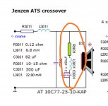
This appears to be the conjugate for the resonance impedance peak. It would not be changing the response unless the amplifier has a finite and noticeable output impedance, which the average audio amp doesn't. The scope of this filter is outside the normal cross so it works even when you remove the other components.
The question is, does it help?
The question is, does it help?
The RLC is a 110Hz acceptance filter.
I suspect there must have been a peak at that frequency so this filters it out somewhat.
I suspect there must have been a peak at that frequency so this filters it out somewhat.
Not sure about that. It couldn't do much without the other components and even with the 6m8/0r12 in series, the 10 ohm version might cut a third of a dB.
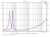
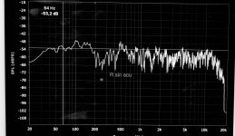
Its tuned at 60Hz. The plot below showing earlier experimentation with the woofer shows the bass resonance is approximately there. In addition, the paragraph just below the schematic implies that it is there for the resonance impedance peak (as with the tweeter).
Its tuned at 60Hz. The plot below showing earlier experimentation with the woofer shows the bass resonance is approximately there. In addition, the paragraph just below the schematic implies that it is there for the resonance impedance peak (as with the tweeter).
Attachments
you do not need these parts, there will be only additional heat created by it. The low output impedance of the amp shorts any effect.
It makes only sense with a passive xover where it compensates the rise in impedance influencing the other xover parts.
With the dsp amp you can do much more than with overpriced discrete parts in better quality, so that was a good choice
It makes only sense with a passive xover where it compensates the rise in impedance influencing the other xover parts.
With the dsp amp you can do much more than with overpriced discrete parts in better quality, so that was a good choice
I thought one key advantage in an active crossover is to eliminate driver impedance and resonance from the equation. All you need to do is effect the correct transfer function at a line level.
Therefore the above impedance compensation circuit (using a whopping 22mH inductor) is redundant?
Therefore the above impedance compensation circuit (using a whopping 22mH inductor) is redundant?
If you mean it's easier, then yes. Besides that filter was always optional.
When did it happen that people started citing cost over sound. It seems about the time that active was becoming popular..
When did it happen that people started citing cost over sound. It seems about the time that active was becoming popular..
The filter is only needed if you drive the LS with a tube amp, which has significant output resistance. The effect is a boomy boost at the resonance.
With a plate amp we have only some milliohms at low frequencies.
With a plate amp we have only some milliohms at low frequencies.
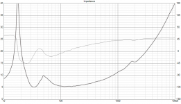
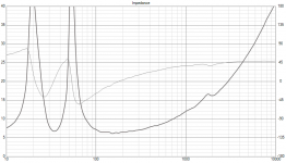
It's at 61Hz as Allen stated and tuned to the second impedance peak of the bass driver. Normally the inductance plus the capacitive load of the impedance cause a resonance of some dB extra around 100Hz. The RLC deals with that. I have done so in a design about 10 years ago (it was noticeable...) and it's rather common practice when crossing over in the low hundreds. But there's no need with an active setup of course.The RLC is a 110Hz acceptance filter.
I suspect there must have been a peak at that frequency so this filters it out somewhat.
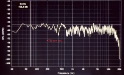
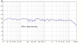
Thank you very much to everyone for your help. I fundamentally read two types of answers that reflect the doubts I had. I must clarify that with the ecu of the Hypex amplification module I can correct the frequency response (see attached photos). so if the function of the LCR circuit is to correct the frequency response exclusively, effectively, I don't need it. however, as mentioned, if the LCR circuit corrected the impedance response of the AT loudspeakers, making the impedance curve flatter, my question was whether this circuit could benefit the Hypex doing its job with "less effort ”. I read quite a few answers that consider that the LCR circuit is not necessary for this last purpose.
BR
Toñi
BR
Toñi
Attachments
- Home
- Loudspeakers
- Multi-Way
- doubt use RLC circuit