FS: Goldring 2200 moving iron cartridge

SOLD- Goldring 2200 moving iron cartridge

SOLD

Used Goldring 2200, currently sells new for $549 in Canada. This is a nice high-output moving iron, said to be made in Japan by Nagaoka. Plays well and appears to be in fine condition, but not sure the mileage. Threaded holes make installation easy. Specs can be found here: Goldring 2200 Cartridge

$175US obo.

Attachments

  • IMG_20210117_130858.jpg
    IMG_20210117_130858.jpg
    365.8 KB · Views: 107
  • IMG_20210117_130814.jpg
    IMG_20210117_130814.jpg
    844 KB · Views: 97
  • IMG_20210117_130832.jpg
    IMG_20210117_130832.jpg
    373.8 KB · Views: 94

AmpCasq: an OPA1622 integrated headamp project

Hi All,
Like some of you I followed with great interest the thread 'New Audio Op Amp - OPA1622' by TI’s Johnnc124. I wasn’t initially specifically interested by headamps but as the OPA1622 was simple to implement and was supposed to provide good results I decided to setup a project with it. More than building an headamp this project was aimed to confirm I could achieve designing a PCB with a CAD software and also soldering SMD devices, including ones in DFN or QFN package.

I’have finally been through all steps, I’m happy with the result (OPA1622 sounds very good !) and I’m now confident to move to projects that will require complicated PCB and good soldering capabilities.
Now, I have to finish assembly and testing of a Salas DGC3 in order to do some comparisons!

The main requirements for AmpCasq where :

  • It should stand in a small aluminum box, in order to sit on desk
  • It should be powered by an AC adapter I had, which provided 17VDC
  • It should have a volume control
  • It should have RCA and jack 3.5 inputs
  • It should have jack 3.5 & 6.35 outputs
  • It should allow me to experiment crossfeed
  • Final price should stay under control

About the schematics:
Regulators:
Ampcasq was designed in September 2016, at this time LM27762 was announced but not available. So, I did stay with LM27761 for -5V and LP38798 for +5V; LP5907 was a bit short on current. The 7805 lifted by R17/R12 was added to limit LM27761 input voltage to 5.5V, its max value. 7805 allow Ampcasq to be powered by any DC source from 10V to 35V, 300mA max.
Power Input:
D1 to protect against bad connection.
D2, R23, R10, R11, C24 to manage the Enable pin of the OPA. Objective was to avoid noise in the can at power up/down. This partly works: mute the output when enable Low (<~0.8V) but can’t avoid noise in can when power supply capacitors are discharching and OPA1622's supply getting out of tolerance. On power off with SW1, OPA1622 is muted as C24 is quickly discharged through R23, D2 and SW1. D2 is a Schottky, not for speed but for low drop (Vf close to 0.3V).
Crossfeed:
It is based on an Xen-Audio (EUVL) paper: Xen Audio cross feed.
There’re three positions for the switch: Low Xfeed – No Xfeed – High Xfeed. Low Xfeed is Ok, High is exaggerate: there’s too much bass boost. After some listening sessions I finally do not use the Xfeed.
Gain + out
Not much to say.


Attachments

  • AmpCasqV3_Schem.png
    AmpCasqV3_Schem.png
    85.3 KB · Views: 3,704

12" woofer for SEOS12 build, 12PLB100?

SEOS12 build

I'm starting a build based around the SEOS12 waveguides. I'm looking for a 12" woofer to use in a sealed cabinet. These will be used full range with a multi-sub setup so I don't need deep bass extension. The AE TD12M is a possibility but would be stretching my budget. The B&C 12TBX100 as used in Geddes' Abbeys looks like a good option for a bit less money than the TD12M's. While looking through B&C's 12" woofer lineup, I came across the 12PLB100. I haven't seen too much discussion of this woofer. The specs listed on B&C's website for it show it to be a couple of db more sensitive than the TBX100, 97 vs 95. If the Thiel-small parameters are accurate it looks like it might work as well or even better in a sealed box than the TBX100. The FR response shown looks a bit flatter than the TBX as well. It's not clear to me if and what the motor differences might be. Both list aluminum demodulation rings, but on Parts Express it claims dual demodulation rings for the TBX. Anyone have any experience or thoughts on the 12PLB100's?

FWIW, I've got a pair of B&C DE250's and DE500's arriving soon for the waveguides. I know that compression driver sensitivity on the high end drops quite a bit on a CD waveguide. If the 97 db figure for the PLB is accurate, would that potentially be too high to mate with either of these compression drivers once they are eq'd back to flat response? I'm interested to try out foam plugs ala Geddes in the waveguides as well so it seems I might lose a db or two of sensitivity from the compression drivers for that.
Dan

Review: Scanspeak 10F/8414G10 Discovery 4 inch Fullrange

Review here:
Scanspeak 10F/8414G10 Discovery 4 inch Fullrange


Cliff's: Really good fullrange driver. Nice on/off-axis response linearity with the apparent breakup pushed out to ~16khz. A mild rise in output on the top end (to help combat the otherwise falling response off-axis) that could be easily flattened via DSP with a shelf filter if one were so inclined. Great usability above 300-500hz for higher output (to help overcome the mid-80's sensitivity). Truly an impressive driver for only $73/each (as of this writing).


IMG_2240.jpg

first multi-way

Hi multi-wayer,

First post here, I used to build no xover speaker ;-)
I'm the owner of an old lady, Sonus Faber Electa Amator II and I like what they give me.

I would like to challenge them and looking for a two way who will outperform them.
Bookshelf, floorstander, whatever.
Room is small, around 15 sqm, budget is flexible.

Any idea?
I like that kind of speaker:
Ellipticor-1
But some bad reviews about tweeter measurement are online....at that price...and the best component doesn't give the pbest performance ;-)

Any idea around that enclosure (available as flatpack, always good ;-)

Thanks

help me about this amp

I've been working on this circuit for a long time. I am not an expert, I just love working on electronics and circuits. I wanted to improve a circuit that I made before. Do you have any suggestions to correct mistakes I made or improve the circuit?

"nothing I designed, it's all just quoting forum experts' designs. "
Thank you.
its google translated.

Attachments

  • 17.PNG
    17.PNG
    107.3 KB · Views: 222
  • IMG_20210127_120530.jpg
    IMG_20210127_120530.jpg
    275.1 KB · Views: 212
  • IMG_20210127_120538.jpg
    IMG_20210127_120538.jpg
    227.8 KB · Views: 185
  • 05-1khz.PNG
    05-1khz.PNG
    108.2 KB · Views: 199
  • 06-20khz.PNG
    06-20khz.PNG
    111.9 KB · Views: 198
  • 07-.PNG
    07-.PNG
    73.5 KB · Views: 96
  • 08-1khz.PNG
    08-1khz.PNG
    67.2 KB · Views: 96
  • 09-20khz.PNG
    09-20khz.PNG
    70.8 KB · Views: 87
  • 10-50khz.PNG
    10-50khz.PNG
    67.4 KB · Views: 91
  • 11-100khz.PNG
    11-100khz.PNG
    59.7 KB · Views: 83

Dayton Audio Ultimax 10" Problem

Alright so i bought this subwoofer from parts express, a mass diy audio distributer. I bought this sub with a 12" passive radiator, 4 6.5" full range boss audio speakers, a 1000RMS watt amp, and an 800RMS watt amp. I have the Ultimax 10" on the 1000RMS watt amplifier. Heres the specs of the subwoofer:
Resonant Frequency (Fs)26.9
HzDC Resistance (Re)3.2 ohms
Voice Coil Inductance (Le)1.28
mHMechanical Q (Qms)3.08
Electromagnetic Q (Qes)0.59
Total Q (Qts)0.49
Compliance Equivalent Volume (Vas)0.83 ft.³
Mechanical Compliance of Suspension (Cms)0.15 mm/N
BL Product (BL)14.5
TmDiaphragm Mass Inc.
Airload (Mms)227g
Maximum Linear Excursion (Xmax)19
mmSurface Area of Cone (Sd)327.8 cm²

This subwoofer, when pushed only a small amount, causes a quite loud mechanical noise. The spider is not coming loose. I made sure to do plenty of research on this sub before purchasing, and I have seen people throw 7k watts when the sub itself is 500wrms. I have watched multiple videos showing ranges of 800-7k watts being pumped into this thing and it's excursion reaching the base of the mounting holes (extremely far). I dont know what is causing this mechanical noise, I have tried several different amps ranging from 200 watts, to 1000 watts. I'm debating sending this subwoofer back to the manufacturer, but I'm afraid of having the same problem occur with the next one. Please somebody help.
Subwoofer:
https://www.parts-express.com/dayton-audio-um10-22-10-ultimax-dvc-subwoofer-2-ohms-per-coil--295-510

Dynaudio 3.3 or ScanSpeak Discovery 861

Hi to everybody.
I'm the owner of a Dynaudio 1.8 not MKII (amp Restek Fable). This loudspekers are with me more than 20 years and I think it's time to change.
I have the oportunity to purchase a second hand Dynaudio Contour 3.3 priced in 1.800€, 20 year old also, but I think will be an upgade from what I have nowadays.
I'm also considering the posibility of assembling the ScanSpeak Discovery 86
What do you think is the best option?
ScanSpeak drivers are similiar to Dynaudio ones, is this statement correct?
Thanks for reading and many thanks for answering.
Regards.

Edit
Which are the diferences in sound between this two options?
Discovery-861 and this EKTA-mkII

Filterless Class D with TPA3126D2

I’ve been experimenting with the TPA3126D2 in filterless mode and am blown away by the results. Because it runs so cool I use them directly connected to the speakers in the enclosure so no need for speaker cables. While I know some folks worry about RF emissions, I’ve designed the speaker enclosures as grounded faraday cages to contain any possibility of becoming an unintentional radio station!

I’m wondering if others have experimented with some of the newer class-d amps in filterless mode. If anyone is interested I’m glad to share details and a PCB I’ve designed to minimize the layout size as well as provide extra power filtering and isolation of analog/switching power.

FS or swap: blh with fostex 208 ez drivers.

Wilmslow audio cabinets housing fostex 208 (barely run in) drivers, with dedicated fostex ft17 supertweeters, crossing at the recommended frequency by fostex.
These are bloody heavy cabinets, so for safety, I will remove the main drivers when collected. Of course I will on the day transfer the cabinets to my garage for socially distant collection, so please bring someone to help lift.
I have sprayed these with about 10 coats of undercoat and the same top coat, matt black, it's far from a shop finish, but looks pretty nice when sat back. I will put these on castors as well, so you can position, but I do recommend putting them on spikes when final placement achieved.
Internally wired with pure silver cable, with additional pure copper wire.
Please note.
These won't come with spikes and
I will provide some kimber cable links for the supertweeters (not shown)
Again these are flipping heavy, so I will remove the drivers for collection.

The drivers are as new, hardly run in, maybe 60hrs (drivers need 300!)
To buy these with built cabinets they would cost about £1200 so grab a bargain.

Pics on request as can't figure out how to use Imgur ��

Swap for most things, possibly decent amplification.

£650 reduced to £500

Wilmslow Horns Wilmslow Horns - Album on Imgur

EL84 Output Transformers

I am thinking of ordering some output transformers from Ali Express. I haven’t used them before but thought I would give it a go.
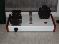
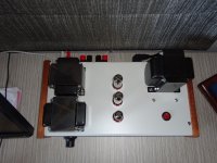
I am going to build an EL84 or 6P14P-EV PP amp.

Can you give some feed back on the following transformers with pros and cons and if it were you what would you order?


No.1
The first ones are
IMG_2777.jpg


£34.13 | 12W 8K/10k small push-pull output transformer, 6P1,EL84,6v6 tube amplifier output transformer, Primary overcurrent ≥80ma

12W 8K/10k small push pull output transformer, 6P1,EL84,6v6 tube amplifier output transformer, Primary overcurrent ≥80ma|Transformers| - AliExpress

Description
High quality 12W 8K/10k small push-pull output transformer
Steel sheet size: 66*30m (tongue width 22*30)
Manufacturer: Kawasaki, Japan
Primary resistance: PP 10K (resistance can be adjusted as required or super linear taps can be added)
Level impedance: 0-4-8Ω
Primary DC resistance: P-P248Ω, the error of the two arms is less than 0.5%
Grade DC resistance: 0-4: 0.35Ω, 0-8: 0.45Ω
Primary inductance: 28H
Primary overcurrent: not less than 80ma
Frequency response: 8-50KH z-1db, 20-35KHZ -0.3db
Withstand voltage: 2000Vdc
Weight: 1.85KG (net weight, without potting)

No.2
Going up in price are these ones
IMG_2778.jpg


£42.96 | 12W 8K: 4Ω 8Ω ultra-linear push-pull output transformer, 40H, suitable for 6P6P, 6V6, EL84, 6P14, 6BQ5 push-pull amplifier

12W 8K: 4Ω 8Ω ultra linear push pull output transformer, 40H, suitable for 6P6P, 6V6, EL84, 6P14, 6BQ5 push pull amplifier|Transformers| - AliExpress

Description
Luge PW-1 broadband response ultra-linear push-pull 8K/4Ω 8Ω output transformer, imitating the output transformer of Shanghai Meiduo brand electron tube R10-2 amplifier.

Mido R10-2 high-fidelity amplifier domestic classic HIFI amplifier, launched by Shanghai Radio No. 3 Factory in 1971, was also the most representative high-fidelity tube amplifier at the time. The characteristic of Mido R10-2 high-fidelity amplifier is that it does not hesitate to build Hi-Fi on the output transformer. The output transformer and the power transformer are the same size, which is very rare in the past tube audio. Not only is the material heavy, but the workmanship is very good, the sound is extraordinary.

Mido R10-2 high-fidelity output transformer adopts four-clamp one-winding method, adopts a core with a large cross-sectional area, increases the number of turns of the primary coil, and has a unique winding structure. The effect is outstanding, and the sound quality is now not used to lose thousands Imported transformers of the same specifications.

Z11 core winding measurement system, 76 pieces stacked 40mm thick, wide frequency response, large dynamic, delicate sound! The effect is immediate!

12W8K push-pull amplifier output cattle, suitable for 6P6P, 6V6, EL84, 6P14, 6BQ5 and other tube push-pull amplifier

Iron core is inserted into the core, nylon wire wrapped skeleton, high-quality oxygen-free copper enameled wire winding, using 4 clips 3, positive and negative winding, layered section winding, to minimize leakage inductance and distributed capacitance.

When the parameters are measured at 1KHZ, the inductance of P1 P2 is about 40H, the leakage inductance is about 60mH, and the distributed capacitance is 2300PF.

The primary copper resistance of P1, P2 is about 475Ω, the secondary 4 ohm copper resistance is about 0.5Ω, and the 8Ω copper resistance is about 0.6Ω.

The total volume is 80×69×70mm, and the weight is 2.8Kg/pair.


No.3
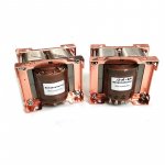
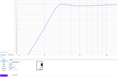
The next one is an amorphous C core design
View attachment 1


£75.20 | 12W Amorphous C-type Core Push-pull Output Transformer Pr10K Se 0-4-8 Ohms for Tube Amplifier 6P1 6P14 EL84

12W Amorphous C type Core Push pull Output Transformer Pr10K Se 0 4 8 Ohms for Tube Amplifier 6P1 6P14 EL84|Transformers| - AliExpress

Amorphous C-type iron core 12W10K push-pull output transformer cattle 6P1.6P14, EL84 push-pull machine for application, layer winding process, CNC drying! Vacuum dipping paint!
Friends of the fever industry have a lot of controversy about the various output transformers that are processed by EI iron core and amorphous iron core. The C core has a good magnetic circuit distribution structure. Similar to the cores of 3,068a and 171 of the Western iron core, this type of core structure is advantageous for coupling and leakage, because the magnetic flux density is relatively large (material, related to the thickness of the sheet), and the second is because of the primary relative secondary The distributed capacitance is the thicker the layer in parallel or the larger the distributed capacitance. The unique physical structure of the c-type core is more conducive to medium to high transmission! However, the C-type iron core also has the disadvantage of poor overload capability. The reason why the sheet is too thin and the lamination factor is too good, but it cannot withstand the shock and overload caused by the back electromotive force of the speaker, not to mention the stronger the counter-electromotive force of the speaker with higher power, so we Independently designed and developed C cattle products, whether it is single-ended or push-pull output transformers are controlled below 30W, audio is a science, we constantly strive to explore every moment! We insist on good sound and low price products is the direction of future development. . . . . . .
Specifications:
Material: British amorphous 4C core
Impedance: 10Kpp (0-4-8) (default without super linear pumping, can be customized with 16 ohm impedance output)
Impedance: P1----P2 (358 ohms) P1-----B+----P2 (178 ohm upper and lower arm error less than 1 ohm) 0-8 ohms (0.5 ohm)
Inductance: P1--------P2 (about 33H)

Bandwidth: 20HZ----------40khz (-1db)

Weight: 1kg

Three-dimensional: 88*68*76

I would appreciate what you think would be worth trying

Thanks

(I have no link with any of these )

Attachments

  • IMG_2779.jpg
    IMG_2779.jpg
    92.2 KB · Views: 1,055

Pioneer DV-310 , power supply dead

Hello everyone !

In the attached diagram I replaced the POWER CTL IC with a new one but the only secondary stage semnificative voltage more than 1V is -5V on C520 (instead of -28V).

Also on IC501 pin3 I don't understand how should be 4.69 V and 9 V the same time.

Primary stage voltages marked by red refferenced to primary stage ground.

During measurements PSU disconnected (no load, no power-on voltage).

It seems it is in std-by / protection mode.

Can not standalone power-on on pin 10 CD 502 connector due all secondary voltages less than 1 V.

Attachments

  • service-Pioneer-cumul.jpg
    service-Pioneer-cumul.jpg
    633.9 KB · Views: 56

Asus X59SL "started" but no beep, no display, no cooler

Hello everyone !

On an Asus X59SL used for a midi controller the fan does not start anymore, there is no initial beep, the display no longer lights up , the processor does not heat up. I tested the ram, it's ok, the adapter works, the battery is fully charged in 2 hours, the operating LEDs - power, HDD light up, there is a hard stop after 4 s, the DVD is still trying to initialize something, If it has someone diagram or at least something similar or in what sequence to check the MOS-FETs on the power supply.

Thanks in advance !

FS - Alexw88 Balanced preamp pcb!

For sale surplus double side PCB for famous Alexw88 balanced preamp!!

DIY audio balanced preamp


Populated PCB = 25 EUR/pc ( 4 pcs available)
PCB = 8 EUR/pc ( 6 pcs available)

For 4pcs togethe free shipping!
WU, Moneygram, bank transfer accepted.


RGDS
Jazzy

Attachments

  • 04062011593.jpg
    04062011593.jpg
    171.9 KB · Views: 385
  • 04062011592.jpg
    04062011592.jpg
    147.3 KB · Views: 375
  • 04062011591.jpg
    04062011591.jpg
    124.9 KB · Views: 376
  • bpre_schematics.gif
    bpre_schematics.gif
    41 KB · Views: 372

Mazama

I've built a pile of Unity horns over the last few years, but haven't been 100% happy with any of them. (I like making speakers more than finishing speakers.)

An issue I had in 2019, is that my 3D printer couldn't make waveguides that are very large.

I bought a flashy new 3D printer, and it absolutely sucks. It's horrible. Possibly the worst 3D printer I've ever owned. (Creality CR10 if anyone's curious.)

Due to all these issues with 3D printing, I had the idea of doing a hybrid. Basically taking an existing waveguide, 3D printing a 'plate' to mount the woofer to the waveguide, and then make a crossover for the thing.

WLzehEB.jpg


61BqkKR.jpg


6Yk4Gxh.jpg


X0zlumN.jpg


QooSROO.jpg


AHJy8Jx.jpg

Mainboard diagram for Samsung CA31 Media Box Tuner Receiver - for PS-42P2SB

Howdy !

Does anybody has the mainboard diagram for Samsung CA31 Media Box Tuner Receiver - for PS-42P2SB ? The PSU is working well but due a short on mainboard is clicking - that clicking noise is the PSU's voltage regulator repeatedly shutting off the power and turning it back on. Something is preventing the PSU from delivering it's power to the MoBo so it just keeps spiking over and over.

Mainboard diagram would be appreciated.

Attachments

  • 06-# Troubleshooting_1.jpg
    06-# Troubleshooting_1.jpg
    366.9 KB · Views: 64

Sony CDP-M33 skipping - not the obvious causes

I have "collected" from the recycle centre this mid size CD player Sony CDP-M33. Considering where I found it, it is in excellent cosmetic conditions and also internally is very clean. It has problems though and it is driving me crazy: it randomly skips back and forth in the first three tracks of many CD's.

The pick-up is a classic KSS-240A (still Sony original) but the control loops are "digital" and do the auto calibration. I have thoroughly cleaned the sledge rails, both the steel rod and the white plastic rail; I have cleaned the sledge motor and gears and the pick-up slides on the rails smoothly and with minimal effort. I tried replacing the pick-up with a new replica, but I always get the same result, it skips in the first 10 minutes of playback; after that it plays flawlessly until the outer edge of the disc.

All electrolytic caps are Elna, but none appears to have the slightest hint of leakage; the control board does not have caps at all.

What could be the problem ? I know this player is worth nothing, it is just fun playing with it.

Help identifying lme49710 preamplifier

Hello there, I have recently bought a lme49710na based preamplifier and can't find any information on it. I would like to ask the community for some advice on what it is based on, what benefits it has and if the characteristics can be changed with a simple opamp drop in ,like for like replacement, it currently sounds a little bright and bass light in my system.
Any information would be greatly appreciated. Please note I am a complete novice so please use layman's terms if you can.

Attachments

  • 20210127_163218.jpg
    20210127_163218.jpg
    964.5 KB · Views: 150
  • 20210127_163238.jpg
    20210127_163238.jpg
    716.3 KB · Views: 117

TPA7498 amp suitable PSU for modding

Hi.
I have purchased a TPA7498 based amp and I try to re-use what I have laying around where possible so looking to see if this PSU is suitable.

I salvaged a few of these from when we had a telephone system upgrade at work.
They are Siemens PSUs and look to be very well made.

LvjJF4zl.jpg


EYx8IMWl.jpg


YaPzXwBl.jpg


As can be seen they are 54v output so..

Firstly are they suitable as an audio Power supply and if so what is the best way to reduce the output voltage?

Is putting the output throught a buck converter a no-no?

TIA

Anthony

Binson e4t feedback

Hi guys,
my english is bad so I bounce presentation and my sentences will be short and some time these last could be strange.. I beg your pardon for this...
I have a echorec binson e4t (I attach the schematic). If I increase "length" (feedback) I have only max 4/5 repeat even if I put on max the internal trimmer.
how can I try to edit in the feedback circuit for add the number of repeat?
thank you and excuse me for errors and ignorance
Luca

Attachments

First MTM/MMT build -sanity check

Hi,

For ages now I have been using some repurposed upcycled boxes to house my TV/Movie speakers.

They use Fountek FW100B 4" midwoofers

https://www.google.com/url?sa=t&sou...FjAAegQIAhAB&usg=AOvVaw1ZutxADGVERa9BcsRLQaus

I have 2 pairs of these woofers, and so I am planning to build either MTM or MMT(2.5way) with them.

In MTM, the C to C distance between the two woofers will be about 8 inches.

So I'd guess, (13500/8)/4 = about 400Hz.

I guess I need to low pass lower than this?

I'm planning on using Tangband W3 1285SG as midtweeter, which *should* be OK with a 400Hz high pass.

I am intending, in the beginning at least, to use as low order passive XO as I can, probably 2nd order, though I'd prefer to keep it simple, as possible, without huge compromise.

It seems with a 400Hz XO, I may just be able to get everything within 1/4 wavelength

In TMM, the 2nd woofer would be used as 0.5 way, providing BSC support.

I feel this may be more complex than it seems as the low XO at 400Hz will be below BSC frequency, which I guess estimate at 800Hz - will the effort be worth it?

Any glaring errors in my thinking?

Decca Ribbon Horns - 3D printing..?

Hi All
I am tempted to try building from scratch a replica of the old Decca ribbon tweeters - though the horn loaded version.

To that end I am wondering if anybody has information on the geometry of the horn - with a view of getting it 3D printed… better still if there is an STL file for such an animal in existence – the STL file being essentially a digital 3D model of the object to be printed.

There are numerous firms which offer 3D printing around – or better still local geeks who may have a 3D printer at home….
Anybody else want to come along for the ride….?

Cheers

Attachments

  • 3d horn.jpg
    3d horn.jpg
    16.4 KB · Views: 123

Drawing load lines for parallel PP OP stages.

I know this has been covered before, but not in great detail in terms of Zpri. For bog standard PP with two valves we 1/2 the OPT Zpri for class A,1/4 it for class B. So for two valves in parallel does that mean we divide that by 2, EG 1/4 for Class A & 1/8 for Class B?


I feel i should have this straight in my head but for some simple calculations my brain starts going into meltdown,going around in circles.


Andy.

V-I limiter problems

Hi,

I've been trying to add a V-I limiter to an amp design but I can't get it to work properly in the simulation. It's intended to limit the output current to 8A and it is doing that on the positive half-cycle. However, there is no effect on the negative part. I can't figure out what the problem is. Any ideas?

Thanks,
James

Attachments

  • VI limiter.png
    VI limiter.png
    176 KB · Views: 142

The Weller W600 I got on my 18th birthday still serves me well

This year I'll turn 52 (If all goes well)... so it will have performed its duties for 34 years now. Quite a testament to the Magnastat "technology"

My WECP-20 I bought 2nd hand in 2007 (And had seen a lot of use by the techs who used it in the field) gave up the ghost (probably the heater). What's up with the replacement heaters price! Daylight robbery. Glad I can depend on my W600.

Seymour onboard differential preamp typology study

Hi,

I just got my hands on a onboard seymour duncan BMP-1 preamp. It's a rev. 04. It was supposed to be the same kind of preamp as the ones coming inside Blackouts pickups, so i got interested.
Seymour duncan promote his preamp using another technic of imbalance compared to EMG differential amplifier with their simple input resistor difference in front of a lm4250.
I found a russian shematic of the blackout preamp on the web. I wasn't sure how good/true it was, but comparing to the BMP-1 preamp pcb, it seems really near, for most of it even for resistor values.
Since it's smd, i cannot get ceramic caps values.

Picture 1 is russian forum's blackout schematic. Picture 2 is with the values and small changes i found on the BMP-1 preamp pcb (one way). Picture 3 is a web photo of the BMP-1.

This seems to be kind a current source differential amplifier + op amp, but i'm not good enough to say more. Really complicate stuff for what it is, so there must be something about imbalance input stuff that explain this choose.

On schematic, there's 3 stuffs i'm not sure about.

1. The "feedback" from op amp output to right fet input. 115k seems high, so it probably a Vref, but there's a cap too. Can't it act as low pass effect injecting negative feedback high frequencies on right input ? Or it is positive feedkback ? or none of that...? This way of referencing op amp output seems me really weird, i would have expected a referencing to a resistors virtual ground...

2.The 680p cap i crossed from the russian shematic, on the left fet seems really high. It's not on the BMP-1. It seems me a error. What do you think about it ?

3.The added capacitor in parrallel with the 12k resistor. Can it be a high pass, or a low pass ?

I'd like to tweak this little onboard preamp. I'll first change op amp for opa1692, bypass output cap with a nichicon muse, and add cap between op amp legs v+/v-.
But it should be interesting to see the effect on preamp response changing stuff around those 3 points (1. adding back a cap, 2 removing this cap, 3 changing cap value). Smd soldering isn't a problem at all.

Any suggestion of tweak ?

🙂

Thanks,

Best regards,

Damien

Attachments

  • c6a73224b822b6b9df5a4a2af31533db.jpg
    c6a73224b822b6b9df5a4a2af31533db.jpg
    34.6 KB · Views: 342
  • Sans titre.png
    Sans titre.png
    369 KB · Views: 317
  • 11356802_800.jpg
    11356802_800.jpg
    54.4 KB · Views: 303

Best Midwoofer in Dipol-Configuration

Hi,

we have many some threads about the best selection of a dipol-tweeter with measurements of the polar pattern incl. backside. (for example in this thread: On the directivity of dipole tweeters)

But whats about the MF? The backside radiation pattern of the mids that i have seen do make some hickups and dont make a perfect dipol8 over the complete midrange.

So the goal of this thread is to make a list over some drivers for the midrange (200Hz-4khz). What is the usable frequency range for a good 8-dipol pattern for every driver (Backside and Frontside)?


Probably we can get some nice driver combinations....

Best regards, Tomas


UPDATE 26.01.21:

Driver List in dipol configuration:

2" Visaton FRS5X usable 1,5-4,5 khz
(Frontside Backside Pattern: https://www.diyaudio.com/forums/att...ectivity-dipole-tweeters-frs5x-front-rear-gif)

3" TC9FD18 usable 1,5-2,5khz
(Frontside pattern: https://www.diyaudio.com/forums/atta...olars-0-90-png
Backside pattern:
https://www.diyaudio.com/forums/atta...ars-90-180-png)

4" Audax HM100Z0 usable till 1,5khz
(Frontside Bacside Pattern:
https://www.diyaudio.com/forums/att...9848301-3-ob-hm100z-0-90-180-4ms-124-vert-jpg)

4"Peerless HDS PPB 4-25/08 (HDS-P830870) usable till 1,7 khz
(Frontside Backside pattern:
http://www.diy-hifi-forum.eu/forum/attachment.php?attachmentid=3199&stc=1&d=1298815177)

...


Driver List in dipol configuration without measurements:

Scanspeak 15M/4624G00 used 250-2,5khz from kaameelis
(Akabak simulation MTM: https://www.diyaudio.com/forums/att...woofer-dipol-configuration-15m4624g00_mtm-png)

SB17CAC used till 1,5 or 2khz from CharlieLaub
(In Thread: In Pursuit of the 20-20k dipole)

S 5 Electronics K 12-G tube amplifier for sale

Tube amplifier in good shape original from Usa.Plug and play option.Tubes in verry good shape.Amplifier is working and sounds great.Original transformer made for Usa 115 volts,but I will give the buyer another transformer for use in 230 to 115 v so the buyers from EU cam use this without problem.Price 150EU plus shipping or best offer.Plese look for data on internet.

DIY Audio Noob needs crossover help

Hi! This is my first post in the forum, so i hope i dont ask some dummy stuff.

Im studying product design and for a little holiday break project I wanted to build some 2-way speakers, specifically 2 two-ways for left and right and a seperate sub. I've figured out most of the things (i think) like the needed amp, woofer etc.

Im gonna build the enclose myself, but there's still 2 open questions:

What kinda crossover do I need for my 2-way speaker design?
Im planning to use a "full range" driver (70-20.000hz, 8ohm) and a small tweeter (3.500-40.000hz, 8ohm).

Is that crossover way to "big", should I just get a driver with less range as i would be running a sub and tweeter anyways?

In any case how do I choose the right Hz for my crossover? Most of the things I can find are either way over my head or made to for a sub/midrange crossover.

If any of this is completely dumb im sorry, just not familiar with this stuff at all.

Thank you!

cheers,
Felix

Simple circuit for tube char and matching

I have a bunch of VT136 and 12AT7s that I'd like to measure and characterize a bit.


Was thinking of making test circuit with a resistor selector switch on the plate and cathode circuits. Ground the grid, and use a pot to set the screen voltage


Then run various resistor combinations, measure Vc, Vp, deduce Ia then fit the data to get the Ia transfer function.


Is this right or am I omitting things?

Reamp Box Output Impedance

Hi, the classic or usual schematic of a Reamp Box is one which has around 10kOhm output impedance to replicate the DC resistance of a guitar pickup. Has anyone experimented with adding a 250K pot as an 'extra' output volume control to replicate the guitar volume knob? I would add it after the 25K pot in this case. I think that this would interact better with low input impedance guitar pedals such as the Fuzz Face.

What do you think?

Search tutorial : sigmastudio + rew

hi,

i did the diy dsp from freeDSP | An Open-Source Low-Budget Audio DSP witch is programmable with sigmastudio.

i want do build up a 2.1 system with my existing speakers/ amplifiers and this dsp.

is there a tutorial out witch shows how to optimize a subwoofer by measuring it with rew or another measuring software and import these meassurings to an equalizer in sigmastudio?

thanks for help,
john

subwoofer is a closed cantoon gls50 (30 cm diameter), dsp is working !

Biggest engineering mistakes in audiophile gear

Have you come across design flaws that make you wonder how such bright people could make such poor decisions?

I just did today, when I discovered the Audio Research VT200 amp. Now, people will rightly point out that its main flaw is not unique to this amp. But, that's not really the point. The point is that the flaw is so egregious that it should have never gotten past the suggestion phase (and shouldn't have been suggested by any engineer worth their salt).

I'm not an engineer and I know better, which says something about how egregious the design mistake is.

What is it? A teeny-tiny fan (small fans are typically noisier than large fans for a certain CFM due to them requiring higher RPM) that's so loud that when the Stereophile reviewer moved it far away it could still be heard. How, on planet Earth, does it make sense to spend thousands of dollars pursuing audio quality and simultaneously throw in fan noise to oppose that goal?

It doesn't. It means the design is a mistake and should be scrapped and completely re-imagined.

ar-vt200-1.jpg

ar-vt200-2.jpg


My guess is that the fan is (in addition to being small — something that looking at the photo makes clear) a single bearing ball bearing design, which is basically the noisiest type of fan there is (although niche designs like blowers might be worse — I am talking about standard computer-style fans for airflow and for radiators). Single bearing ball bearing fans are often used industrially due to their low cost and long life, even though they're loud. Dual bearing fans are a bit quieter but not as quiet as more modern bearings like fluid dynamic (FDB), the floating air bearing, etc.).

The placement of the fan here also looks similar to how a fan is placed on a computer radiator (it's against a resistant barrier). Placing fans in restrictive situations necessitates the use of fans designed for higher pressure versus higher airflow. Higher static pressure models (which often have the large motor hubs for their size, like the one in the photo) are much more effective at combating resistance but they are also noisier per CFM. That's not good when you're designing something for audiophiles. What seems to be ideal is to have a big fan without much restriction in its placement so the air can flow over the tubes. I would think that having two 200mm fans would be better, in order to get flow over all of them but maybe that's overkill. Better flow coverage means lower RPMs are needed, which means less noise. Having the amp split into two mono boxes seems better because the heat is less concentrated and a separate fan on each means the airflow isn't going to conflict between the fans.

There were 200mm fans in existence (and even larger). Most of them were old-style sleeve bearing fans that must be placed vertically. Sleeve bearing fans, when mounted vertically, can be the quietest fan type at lower RPMs, though. One fan that was not a sleeve bearing was Antec's "Bubba" which was a dual ball bearing and relatively noisy. The problem with sleeve bearing fans, even when mounted vertically, is that they tend to have the shortest lifespan. Ball bearing fans simply get louder over time. But, ball bearing fans also have a fatal flaw. If they are dropped/knocked too hard they can be ruined. Sleeve bearing fans can take abuse.

Since tube amps require annoying tube replacement work it seems totally reasonable to have the customer replace their sleeve bearing fan every so many years. The key to that is to make it easy to remove and replace the fan. I have seen sleeve fans last quite a long time, too — so this hassle would be quite a lot less of one versus having to replace tubes, I would think.

This amp, if designed as it was to put so much heat into a single case, should have had a big (like 200mm) thick very slow RPM vertically-mounted sleeve bearing fan to keep the tubes cool — using an enclosed tunnel to channel the airflow over the tubes (as Dell does in its computers, for instance). Big OEMs like Dell realized that using airflow enclosures keeps noise down and improves cooling reliability.

Noctua, in case no one knows, has released FDB (fluid dynamic bearing) 200mm fans, which can be mounted horizontally and are quieter than sleeve bearings at higher RPMs. For an amp, though, very low RPMS with a very large fan should be sufficient. If not, use two. The horizontal ability of the Noctua means you can build a current-gen XBox-style tower to move hot air vertically as it prefers to. (AMD released a prototype machine before Microsoft did that had a vertical wind tunnel design. SilverStone also worked with a hybrid between the standard ATX case and vertical airflow.) If anyone wants to fix this Acoustic Research design by re-doing it, do it that way. Or, the amp should have been two mono blocks to keep the heat spread out more (possibly with a large fan for each at a very very low RPM). No one should be hearing fan noise from a home audio amp, especially a high-end one! Audiophile means the person loves sound quality. Fan noise is the opposite of that. If an amp is designed for live rock concerts and other high-noise high-SPL situations that's, of course, very different.

Whenever I see amps with small fans I shake my head. When I see one that requires so many expensive tubes because it produces so much heat and has one paltry tiny fan I really shake it.

Serious drawbacks:

• The fan!

• Too much heat crammed into too small a physical space.

• Too many expensive tubes to replace.

• Too heavy for safe lifting for many people.

• Ugly (especially the all-black version). If you're going to have all those tubes then show them off and don't use ultra-boring black box exteriors. Tube amps should look retro chic — understated and elegant — not a big boring black box. (Note that retro chic doesn't mean covered with big florid lettering and lots of logo trash which is a contemporary trend with tube amps and even the tubes themselves. I looked through an article that showed affordable tube amp options and, guess what — the only one that looked nice was one designed in the 50s.) Aesthetics are a matter of taste but only to a point. Tubes should be both seen and heard. Otherwise, a person can get everything they can do from solid state much more cheaply.

Stereophile said:
And because the VT200 is fan-cooled, you should also think about placement. Don't just set it down on thick carpeting—place it on a flat surface, or, better yet, an amplifier platform such as the OSAR amp rack I used. Place it as far from your listening position as possible. The fan is pretty quiet at medium speed, which is how the factory supplies it (you can bump it up a notch or slow it down, if you wish), but even with the amp 10' away from my listening chair, I could hear the fan faintly between tracks and CDs. I never found it annoying or intrusive, but your mileage may vary.

Yes, my mileage varies. If I spent thousands on an amp and thousands on speakers I don't want to have spent thousands to hear avoidable fan noise. I also don't see how having to find far away placement strategies is a bonus.

DSP/Amp board combo that supports 2ch input to mono output with crossover

I'm really struggling to find a solution (low cost) that can do what I need. What I want to build in a single two-way bluetooth powered speaker with an active crossover.

Needs:
-Less than $100USD for DSP, amp, bluetooth module, and PSU
-Must covert 2-ch input to mono output
-Must have crossover and parametric eq
-decent quality amp design (2x25w range)


I think a RPi with a DSP board and amp board would work but it is starting to get too costly. Looked at some 3e Audio/Dayton audio boards but I can't confirm if I can mix channels.

What are my options? Maybe I am just not searching for the right thing.

Comments on the LL2785B design

Here is the reply from Mr Lundahl for the LL2785B design.


Comments on the LL2785B design

The big challenge, when designing audio transformers with reasonably good HF
response, is to minimize leakage inductance AND minimize capacitive coupling.
Unfortunately these two ambitions are normally in opposition. In order to
reduce leakage inductance we increase the sectioning of the transformer, which
means that we interleave parts (sections) of the primary winding with parts of
the secondary winding. But one can easily see that the more we increase the
sectioning (in order to reduce the leakage inductance) the more capacitive
coupling there will be between the primary and secondary windings. However, if
the voltage swing across the section interface could be reduced, less capacitive
energy will be stored in the interface and thus the HF response will be
improved.

In our cooperation with Elekit and VK Music we have developed a new winding
structure for improved HF response and in particular for less phase shift in
feedback taps. This new winding structure is used in the new transformer for
the TU-8600S transformer upgrade kit. The LL2785B is built up of six sections,
two primary sections and four secondary sections. It is built with our own
silicon iron C-cores and is wound with our normal stick-winding technique.
What is unique with LL2785B is that its’ sections have been arranged in such a
way that all primary winding surfaces that face a secondary winding have no or
very little swinging signal. For this reason the capacitive energy stored in the
interface between the primary and secondary windings are kept to a minimum.

Per Lundahl


New build SE EL84/6BQ5/6P14P-EV - 2C51/5670/6N3P-E(V)

Close to 7 years ago I built the "Budgy" from Shannon Parks (diytube dot com) and was satisfied with the results. In a moment of delusion I sold the amplifier to fund building an Audio Note kit 4 clone. (PP 6V6).

Not happy with the Audio Note I sold it and am now collecting parts for a new SE 6BQ5.

No longer is the Budgie PCB available and rather than going through a steep learning curve with software to make my own PCB I searched on ePray and found a PCB that looked like it could be used.

It is using the 5670 / 2C51 / 6N3P as a driver and headphone addicts seem to like that tube and also it has found its way into DAC's. It is also used in the El Cheapo amp. Plenty available NOS.

When the PCB arrived earlier this week it was slightly different from advertised, it was missing two tracks and used on the 6BQ5 the pins 1, 6 & 8 as tie points (a no-no). Some older NOS EL84 use some of those pins, so does the 7189A and there can be fireworks when inserting a tube that has used one of these pins.

The values shown on the PCB wer different from the values in the schematic and I had to model it in LtSpice as the vendor was unhelpfull. Did not take me long to get familiar again with LtSpice after not using it for over 10 years.

Loadlines for the 5670 seemed a tad strange too and I found a website where I could model the triodes. (Triode / Pentode Loadline Simulator v.1.0 (20161216 [url]www.trioda.com)[/url])

Mullard in the UK originally specified a 20% ~ 22.5% tap for distributed load and I'll be using that instead of the common 43%. Transformers have been ordered.

Mains transformer will be 240V @ 240mA with bridge rectification and CLC.

Eli Duttman has been raving on about "hash filters" so those will be included.

The TDK 2CP2511 (that has excellent tracking) will be used for volume. There will be some high value and appropriate current rating NTC resistors on the primary which will prevent the filaments lighting up like a light bulb. The NTC's will keep B+ below 300V (filaments draw current dropping the voltage across the primary) and after 60 seconds an Amperite delay relay will short the NTC resistors out of the circuit.

Still undecided on the tube sockets - I searched the web and found that some builders of guitar amps use chassis mounted tube sockets as their experience with PCB based sockets has been less than optimal (cracked copper tracks due to the heat or solder melting) The 7189A can run hot.... (especially the way the guitar players bias them). I am leaning towards using under chassis sockets and soldering nuts to the socket so I can remove them without having access to the back. There will be some stopping resistors going to the socket (and a few ferrite beads).

The circuit orginally used a 220 Ohm resistor but it is in the middle of he PCB and produces a bit of heat so was not too happy with it besides it results in about 240mV ripple which is audible in sensitive speakers. A choke will be used instead.

Not yet decided on the choke I'm going to use, I'm thinking about the 6H Triad Magnetics or the 1.5H Hammond. The 6H will have about 17mV ripple at B+ to the power tubes, the 1.5H works out at about 77mV.

I am attaching the pictures on the original schematic as advertised, the photo's of the PCB and the modelling in LtSpice.

Any suggestions for improvement are appreciated but I am stuck using this PCB (I really do not feel like redoing the PCB). I also will stick to the selection of tubes as the first ones of them have started to arrive.

Pictures of my previous build are attached too but I'm going to try to make it smaller this time so it takes up less space on my desk.

Looking forward to suggestions before I start working on a chassis. Hopefully your input helps with avoiding having to start all over again - I'll appreciate a sanity check. Thanks!

Attachments

  • 2C51 -6BQ5 SE triode PCB.jpg
    2C51 -6BQ5 SE triode PCB.jpg
    79.2 KB · Views: 665
  • blank bottom.jpg
    blank bottom.jpg
    87.6 KB · Views: 558
  • blank top.jpg
    blank top.jpg
    154.4 KB · Views: 491
  • 2C51 - 6bq5 SE UL.zip
    2C51 - 6bq5 SE UL.zip
    3 KB · Views: 109
  • DSC01199.JPG
    DSC01199.JPG
    461 KB · Views: 472
  • DSC01201.JPG
    DSC01201.JPG
    465.3 KB · Views: 522
  • 6BQ5 - 2C51 SE UL.png
    6BQ5 - 2C51 SE UL.png
    82.1 KB · Views: 420

TU-8200R voltage issue

I recently assembled the new version TU-8200R for a friend.
By measuring the reference voltages I realized that in points # 15 and # 16 I have only 210V DC, instead of the normal 265 - 290 as written in the manual.
What do you think could be the problem?
On the other hand the amplifier seems to have no symptoms from a sonic point of view ... everything seems to work correctly.
The power supply voltage in my country is 226V AC.
My set up consists of:
2x 6LGC JJ + 2x ECC82 JJ
Thank you in advance

On A Hippie Trail, Head Full Of Zombie

Back down under after a long holiday.

It's time to do something.
The plan is to do a little bit each day and report here with my progress.

It's your job to kick my butt if I get lazy with this.

Day 1
Fresh pcbs made up.

By end of today, the plan is to have at least one psu board stuffed and soldered up.

If I have more time after that I will start some measurements on new devices I have purchased.

TO DO LIST
Wiring Looms
Install tube inserts
Test Powersupply
Populate pcb
Test amp


Edit: Transformer Specs Added
Pri A: 0—120v (BLUE—GREY) 50/60Hz
Pri B: 0—120v (VIOLET-BROWN) 50/60Hz
----------- SCREEN ------- (GRN/YEL) -----------
Sec 1: 0—19v—25v (BLACK-WHITE-RED) rated at 10.0A rms.
Sec 2: 0—19v—25v (ORANGE-GREEN-YELLOW) rated at 10.0A rms.
---------- MUMETAL BAND ------------------------
Resin Filled Centre = M8 Hole / M8 x 130mm Bolt Supplied.
Total Rating: 500VA.
Secondary winding resistance: 50mOhms each.

Here are the pcbs

Attachments

  • 15784274447646072501565593107438.jpg
    15784274447646072501565593107438.jpg
    414.7 KB · Views: 1,780
  • 15784275336222940717961084785721.jpg
    15784275336222940717961084785721.jpg
    361.2 KB · Views: 1,789

Allen &Heath XONE-92 mixer.

Hello Gentlemen! I own a Allen &Heath XONE-92 mixer. I purchased this mixer for small use in my apartment, not realizing how sophisticated and professional it is.
I am in the NY. area, and I'm looking to sell the unit. I've only used it a few times. Since then it's been hept in its original box and wrappings. The unit is silver- faced, and in pristine clean condition. It has no dents, marks, nicks, scratches or fingerprints on it, just as my other pieces. Being I'm hoping it goes into good hands, is it safe to wrap this unit myself and ship it myself, or have an audio guy ship this?, or maybe consider local pickup as well? 😕

FS: Kit for Quasimodo test-jig

I got these made for myself and have a spare kit.

Includes PCB from OSH Park and all parts to populate.
Asking $50 which includes all shipping and fees.

I've assembled a board with these parts and confirmed it is working as expected.

Picture is of completed board, not kit.

Simple, no-math transformer snubber using Quasimodo test-jig

Attachments

  • zdbik3D.jpg
    zdbik3D.jpg
    216.5 KB · Views: 186

Any 4S Universal Preamp 12a*7 builds here

Hi all,

I am about to order the parts for my first valve build which is a 4S Preamp which can use any 12*7 tube.

Assembled-4S-Universal-Tube-Preamp.jpg


4S-Universal-Tube-Preamplifier-Schematic.png


4S-Universal-Tube-Preamplifier-Power-Supply-Schematic.png


4S Universal Preamplifier for 12A*7 Tubes

I am going to order Hammond 369EX transformer as I am 8n the U.K. and so need 240v

https://www.mouser.co.uk/datasheet/2/177/300-951115.pdf

Further details of the design development and specs of the 4S are found here

The “Universal” Preamp | Cascade Tubes
Has any one built or used this preamp, or any views on the circuit design, or any advice?

Thanks

Cathode resistor for EL84 P-P Triode wired

Hi,

I've searched extensively for a concrete answer here and couldn't find one.
I've built an EL84 P-P in UL (7.6K OPT)
It is cathode biased and has a 270ohm resistor per tube, B+ around 310-315V, giving 35-39mA bias per tube.

For converting this amp to Triode (without replacing the OPT), do I need to increase the cathode bias resistor from 270ohm to 560ohm (per tube)?

A high-level explanation on the reasoning would be helpful too 🙂

Going off of the attached Mullard EL84 datasheet.

P.S Amp is a Tubelab SPP but question is generic.

Attachments

  • EL84 Mullard.PNG
    EL84 Mullard.PNG
    61 KB · Views: 455

Shaving 0.5V of an smps, help wanted

I have two nice Phoenix Connector Quint-power SMPS, the 48 Volt version that can be tuned anywhere between 30 and 56 volts.

However I need these PS to drive a TI TAS5825M Amp that allows for a voltage of max 26.4V

I tweaked the voltage regulator pot a bit by lowering the resistance to ground to get a lower Voltage. This works wonders yet the internal control starts to become unhappy (warning lamp starts to blink) when I drop below 26.6 Volts, so I made sure that this is the lowest I can adjust now.

Since the difference is soo small a Buck converter or a resister network is not practical (I used a calculator and the Ohm values where tiny).

How can I shave off these 0.2V or better 0.5V to stay out of the fringes? Will adding some caps between SMPS and Amp help (all components have some resistance ;-)

Thanks for the help
Peter

SEAS A26 with 27TBFC/G : filter optimising

So I built a few years ago a pair of speakers based on Dynaco's A25, using the SEAS A26RE4 as midrange woofers and 27TBFC/G as tweeters.
I didn't want to spent the extra $$$ for the T35 and couldn't see the advantage of these tweeters, if they had to be padded by an 10 Ohm resistor anyway.
And from what I understood larger tweeters were more directionnal.
The 27TBFC/G has the advantage of going easily down to 1500Hz and has very little distortion. Its efficiency is on par with the A26RE4 woofer. It is also quite cheap. Finally they have protection grids and I was just going to have a children ;-)

I will make new pictures of my speakers to see the build. At that time I presented it in the A26 thread but these pictures are not hosted anymore. I have to say I'm really proud of the wood work that I've done (with some help) !
here is a picture of the cabinets while I was building it :
An externally hosted image should be here but it was not working when we last tested it.


Now I'm just thinking again about the filter part.
I was really happy with the result and therefore didn't want to spend hours working on the filter, now I consider that maybe there is something that can be improved there.

I started playing a bit with XSim, using datas for my speakers to see how they compare with the stock A26 kit.
I found out that one can achieve a very close match, side apart from the impedance (which stays anyway above 6 Ohms):
In light blue, the commercial kit with T35, in dark blue with the 27TBFC/G:
An externally hosted image should be here but it was not working when we last tested it.


But actually in my original design I used a 4.7uF Mundorf Supreme Cap in series with a 9.5 Ohms resistor on the tweeter (still no filtering on the A26RE4).
What is strange is that the frequency response is very far away from linear :
An externally hosted image should be here but it was not working when we last tested it.

Though to my ears it is very well balanced.

What do I miss?

Heathkit AA1640 amplifier

Hello everyone. There was a post sometime back, about rebuilding the Heathkit AA1640, and parts that should be replaced with better parts, and I wanted to know if anyone had that information from a gentleman on this Group by the name of Chris. I have one of these with a bad channel and of course I do have the assembly manual, but with that said, I would like to acquire these must have replacement parts, so I can be ready to go. Some of those parts need to be matched. Thank's to everyone in advance.

Mark

Bluetooth or WiFi to separate left right speaker

Can this be done,

I would like to stream music to completely independent left and right receivers. Each channel with its own receiver speaker and battery supply for portable patio speakers.

Forgive me if this is already commercially available or if I missed an already thread on this topic.

Would like to build a system like this with quality speakers, not compact, at least a couple of cu ft per box.

I am a newbe to digital source.

PCM1792 NOS DAC on Aliexpress

There is an interesting dual mono PCM1792 DAC on Aliexpress which claimed as NOS, PCM-384, DSD-512 capable by seller.

I know that PCM1972 is maximum 192kHz capable.. but when run in external filter mode, you can feed it with oversampled data. Btw, to run these dacs in external filter mode, you have to use some glue logic in order to separate left and right signals from digital data.

As you can see, there is only one logic chip on PCB which is a 74HC157. This chip generally used for switching between two different I2S sources. There is no other logic chip on bottom (seller sent the photo of the bottom side) or upper side of the PCB. If this design is NOS capable, data must be separated in somewhere so I want to ask you that might that be the Atmega88PA AVR chip on the upper left corner?

Other thing is, existence of 74HC157 is in question since there is only one I2S input/source on PCB. So, there is something going-on on AVR side, right?

Attachments

  • H913edc915d8f4cde93f66c7ce1bcc7286.jpg
    H913edc915d8f4cde93f66c7ce1bcc7286.jpg
    144.8 KB · Views: 536

Can someone shed light on the bias adjustment in the Fender Blues Junior

Can someone please help me understand the way a Blues Junior should be biased? There's a ton of different info on the web, some of it outright wrong info, such as stating that the amp is cathode biased etc.

From the service manual (http://schems.com/bmampscom/fender/Blues Junior Service Manual.pdf) I can read that:

"The output bias is derived from the -15Vdc supply. The voltage divider at R31 (R52 in later Rev. but still 22K) & R37 (R51 in later Rev. but still 33K)
determines the bias voltage (-10.7 Vdc). C14 filters the ripple to 1mV or less."

blues_jr.gif
- or see: http://blueguitar.net/new/schem/fender/blues_jr.gif

Now, looking at the instruction video of the late Bill Machrone (YouTube) he states that one should "remove the output tubes or pull one of the red wires in order to lift B+"

He then places the ground terminal on B+ and measures voltage on the brown (transformer ?) wire, and sets a voltage. From the table on his page (Billm Audio >> Setting the Bias) I can see this should be 2,6volts with the stock tube and transformer.

Now, should the tubes not be in the circuit in order to set the bias? I mean, the bias should reflect the individual nature of the output tubes, and in this case also the transformer?

I also see that he has removed both reistors in the voltage divider and replaced them with a multiturn, but I assume that replacing only one of them - eg. R52 with a 50K variable would give the same option to set the bias the way described here?

I would be very thankful if someone could explain this?

Best regards
Hans

What am I doing wrong..? SMPS driving a buck converter :(

Hi all,

I’m putting together a small class D amp setup for my home office.

The topology is:
SMPS (24v) —— isolated 5v buck supply — Arylic wifi streaming receiver
—— TPA3116 board (x2)
—— miniDSP


I am getting some digital interference caused by having both the SMPS and buck supply meanwell SPBW06G-05 Blockedconnected.

If i run the Arylic from an external usb supply, there is no interference. I have been running everything off of a 12v 5A SMPS for testing.

The attached scope capture shows the input to the buck supply (yellow trace), the output of the supply (blue trace) and the single-ended audio output from the Arylic.

It is quite obvious that the 600kHz switching frequency of the buck supply is being passed both upstream and downstream. It is also visible in the audio signal.

I have tried a variety of filters to get rid of this signal. I have tried LR (4.7 uH, 3.3ohm) and LC filters (4.7 uH, 50nF) on either side of the buck converter but neither seems to have any effect.

Unfortunately the only inductor i have in my parts stash that can handle the current (1A) is the 4.7uH sumida CDRH5D28RHPNP-4R7NC Blocked.

I can probably go grab something else from the office, but i would need to know what specs...

What am I missing here? I’m sure this is easy but for some reason it is getting past me.

Attachments

  • 52EFA7B8-6A6D-4A00-BCF0-29CD6CDFB24B.jpg
    52EFA7B8-6A6D-4A00-BCF0-29CD6CDFB24B.jpg
    905.7 KB · Views: 200

Audio Playthrough on Multiple Outputs PC

How to get Audio Play-through on multiple outputs. I am planning to connect 2 DACs connected to AMP using USB ports and then connect 3.5mm PC Headphone outlet to AMP for Dolby-surround. Is there a way to get Audio Playing on all three outputs at the same time. This will help me switch between three sources with simple help of the button on the AMP.


Here is the setup:


PC(3.5mm Jack) > Dolby Atmos for Headphones > THX-AAA-788

PC(USB-1) > Sennheiser GSX 1200 Pro > THX-AAA-788
PC(USB-2) > THX-AAA-788

Single driver design that excels in the human voice range

I was thinking of undertaking a new project with the goal to produce a no-compromise single mono Bluetooth speaker to play audiobooks and podcasts. I want something that does a great job of naturally reproducing the male and female speaking voice with everything else not being important.

I'm thinking of doing some type of omni-directional or di-pole design where the speaker can be placed flexibly in a room and not have the listening sweet spot limited to a small location.

Anyone have ideas or suggestions to get me rolling on this idea?

VTL5C1 alternatives for channel switching

Hi everyone,

I was wondering what would be a best alternatives to VTL5C1 opto switches used in Soldano amps?
Would this available part NSL-32SR3 be a drop in replacement?
Also browsing the internet I found some drawings using 8-legged couplers there, but cant get any information on which exactly? Here is a fragment of the schematics attached.

Of course people are switching to relays, but heard you would need to do some muting in order to eliminate clicks.
Thanks!

Attachments

  • slo_switch.png
    slo_switch.png
    225.7 KB · Views: 170

Repaired Blues Junior with low B+

Here's a mystery from my latest project: I've repaired a Blues Junior (schematic attached), and have it working and sounding fine. However, when I measure the B+ voltage, it's far lower (at 255V) than the schematic from the manual suggests I should find it (329V). Other supply voltages are similarly low by >20%.

Before the rectifier, I find 256VAC across the PT secondary as expected, and measure 130VAC at the junction of D1 and D3, which matches the schematic.

Pulling the preamp and PI tubes raises all the voltages a little bit, but doesn't meaningfully change the situation. Pulling the power tubes as well leaves all supply voltages at 350V. So, seems to me the power tubes are pulling the voltages down, and I imagined I'd find them running hot.

But no: bias voltage measures -10.6V just as the schematic suggests. I measured plate currents via OT resistance & voltage, and found 15ma (1.41V/91.6R) and 14ma, which seems quite low for EL84s — not at all what I expected! Switching to a different pair of EL84s didn't make any significant difference. Just in case something was wrong with my plate current measurements, I tried paralleling some resistors across the bias supply voltage divider (R51 and R52), to drive the bias to a very cold -16V, but even this left B+ at barely 300V.

In case it's a helpful clue: the problem I found and repaired was that the first voltage dropping resistor in the power supply, R47, had burnt out. The replacement I installed (2.2k 2w) runs warm, 48C according to my IR thermometer, but doesn't seem to be in danger of a similar fate.

Any ideas on what might be going on? Given that the amp sounds fine and the power tubes seem to have low dissipation, I'm tempted to call this a success, but I'm worried I may be overlooking something that will cause problems.

Attachments

New (old) member from UK

Hi,
I'm and ex-Royal Air Force avionics engineer who has practically forgotten all my electronics training.

I'm currently working from home and have had the time to setup a long forgotten Rega P2 turntable and have started to look at DIY amps and power supplies.

I have a TDA7498 amp on the way from China and will look to use some existing PSUs I have.

Looking forward to learning from you.

FS PCBs: UTHAiM, My_Ref Fremen, SS Dynalo, O2, Marsh, Hiraga, M2, SHP XRK

Cutting down on projects, following bare PCBs for sale:

-UTHAiM v1.0 by EUVL; 1 set SOLD

-My_Ref Fremen edition v1.72; 1 set

-SS Dynalo rev 1.1 (with 30x MPS06 and 30x MPSW56 ) by Kelvin Gilmore; 1 set

-O2 Objective2 HPA v1.1 by NwAvGuy; 4 boards

-Marsh HPA; 2 boards

-Hiraga Super 30W rev 1.1 from Jims audio (with 4x 2SA872 and 4x 2SC1775); 1 set

-First Watt M2 tribute (with PSU PCB) by JPS64; 1 set

-Simple High Performance DC coupled class A HPA by XRK971; 2 boards

Any reasonable offer accepted. PayPal or bank transfer

Attachments

  • IMG_20210126_174639.jpg
    IMG_20210126_174639.jpg
    895.4 KB · Views: 232
  • IMG_20210126_174030.jpg
    IMG_20210126_174030.jpg
    990.6 KB · Views: 229

G'day Diyaudio!

Hi everybody,

I'm Ben from Australia, I've been into music all my life and enjoy electronics work as a hobby - this makes a great pairing doesn't it?!

Currently I own circa 70's Solid State gear, mostly Sansui which I like the brand for many reasons.

I carry out restorations, repairs and minor upgrades to amps, recievers and speakers. I'm somewhat limited to my understanding of circuitry though I do learn a lot from here and other places and think that I have a good sense for sonic improvements.

Looking forward to sharing the Diyaudio experience with all of you.

Best regards
Ben

Newark’s house brand Multicomp pro, yay or nay

Hello all, trying to find an answer on this. I have a couple big amplifier projects coming and I’m looking to buy a quantity of outputs. For example if I were to buy the On Semi MJ21193G I could get them in the $6 range. Not a lot, but they’ll add up quick as I’ll need dozens and dozens along with the complimentary device.

Now through Newark I can get the same device labelled MJ21193 made by Multicomp Pro at nearly half the cost. That would be a huge savings. If they’re nearly the same product in quality it’s a no brainer to grab them. If they’re similar to NTE products then I may steer clear. Looking for some guidance!

Thank you,
Dan

Attachments

  • D2A33F76-F17F-4905-A422-B9A72725C994.png
    D2A33F76-F17F-4905-A422-B9A72725C994.png
    920.2 KB · Views: 157

Preamp with tone control

Hi,

Maybe this is not considered high-end, but neither my speaker(s) nor my room has a flat frequency-response.
And sometimes some tracks need more base/mid/treble, whatever.

Well...I've tried to "design" an unbalanced preamp with built-in tone control. (-> differential pair, tone control, mixing stage)

I didn't want to use inductors, so I've tried to gyrate capacitors (=transforming capacitance into inductance, inversely proportional) using FETs.
It's possible to gyrate a capacitor using tubes or op-amps. To keep up the spirit, I want to use FETs, but I don't want to diy op-amps directly (too many parts).

Simulating it with circuitmaker indicated that some of my part's values are wrong. There's no effect on the signal, I think because the FETs in the gyrating stage are not turned on. And there's no gain.

The idea is to use the balanced zen pre as a differential pair, tone control with gyrated caps instead of inductors and a simple mixing stage (mixing the pure signal with the tweaked signal).

Maybe someone can help me fix the circuit.


Yarr, Dave

Attachments

  • zen_eq.jpg
    zen_eq.jpg
    58.6 KB · Views: 1,136

Dayton Audio DCS205-4 Box sizing

Hi!

I'm building a subwoofer for home cinema. I have fronts with nice low end (40-50 hz), so what I want to extend the bass to 25-30Hz.
This is budget diy project, so I've chosen the Dayton Audio DCS205-4 which is around 100USD here in Europe.

I'm plannig to have a 42l (1.48 cf) reflex box, with a 29Hz port tuning.

Will this work with a 100W rated chinese D amp around the 30hz range?

Thanks!

Attachments

  • dcs205-4_data.PNG
    dcs205-4_data.PNG
    28.6 KB · Views: 250
  • dcs205-4.PNG
    dcs205-4.PNG
    34.8 KB · Views: 226
Projects by fanatics, for fanatics
Get answers and advice for everyone wanting to learn the art of audio.
Join the Community
507,825
Members
7,889,803
Messages

Filter

Forum Statistics

Threads
406,318
Messages
7,889,803
Members
507,825
Latest member
dawktah48