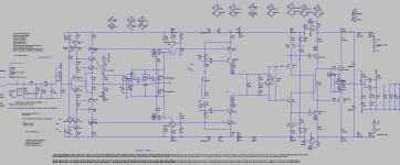
I've been working on this circuit for a long time. I am not an expert, I just love working on electronics and circuits. I wanted to improve a circuit that I made before. Do you have any suggestions to correct mistakes I made or improve the circuit?
"nothing I designed, it's all just quoting forum experts' designs. "
Thank you.
its google translated.
"nothing I designed, it's all just quoting forum experts' designs. "
Thank you.
its google translated.
Attachments
-
 17.PNG107.3 KB · Views: 226
 -
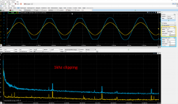
 11-100khz.PNG59.7 KB · Views: 88
 -
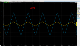
 10-50khz.PNG67.4 KB · Views: 94
 -
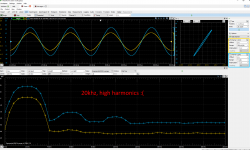
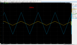
 09-20khz.PNG70.8 KB · Views: 90
 -
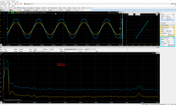
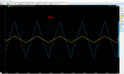
 08-1khz.PNG67.2 KB · Views: 98
 -
 07-.PNG73.5 KB · Views: 100
 -
 06-20khz.PNG111.9 KB · Views: 201
 -
 05-1khz.PNG108.2 KB · Views: 203
 -
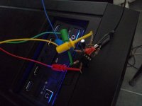 IMG_20210127_120538.jpg227.8 KB · Views: 189
 -
 IMG_20210127_120530.jpg275.1 KB · Views: 215
Last edited:
continue from above
Attachments

You are not an expert, you are a Maestro.
The servo can be done either with single opamp or single capacitor integrator followed by an inverter.
The servo can be done either with single opamp or single capacitor integrator followed by an inverter.
Last edited:
I've been working on this circuit for a long time. I am not an expert, I just love working on electronics and circuits.
Well done!
I wanted to improve a circuit that I made before. Do you have any suggestions to correct mistakes I made or improve the circuit?
Create zip-archive with your LTSpice *.asc file and attach it in your post, this will greatly helps to talk about.
ok, thanksThe servo can be done either with single opamp or single capacitor integrator followed by an inverter.
LTSpice file attached.
Attachments
In general, I'm not a fan of class AB inputs unless you need extreme slew rates, which is not the case with audio power amps. The gain is rather low compared to other topologies. I've used them in power supply clamps where extreme speed was really the only requirement. Diff pairs are quieter and have lower distortion.
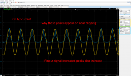
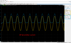
I'm not a fan of the schottky diodes in series with the emitters of Q20, Q21. Resistors are more linear through the zero crossing and help with thermal stability, too. I realize you are trying to prevent the OP transistors from switching off, but I think the diodes are actually hurting your THD at 20 kHz. I could be wrong, but that's my intuition.
As Kokoriantz mentioned, your DC servo is a non-inverting integrator followed by a non-inverting buffer. Replace with a single inverting integrator with output through R30 (the 47K). Disconnect the GND side of R30, and connect it to the integrator output.
Q51 and Q36 look like terrible series-pass regulators that will give you rail voltages that dip inversely proportional to current draw, and the regulator output voltage is also proportional the the transistors' betas. You need voltage references on the bases of those transistors.
The way that you have cross-coupled the pre-driver and driver stages is clever, but it prevents you from running different bias currents in those 2 stages. I suspect the optimum bias for the driver stage is higher than what you are running.